EP1422136A2 - System zum Einziehen von Vortriebskomponenten an Booten - Google Patents
System zum Einziehen von Vortriebskomponenten an Booten Download PDFInfo
- Publication number
- EP1422136A2 EP1422136A2 EP03380270A EP03380270A EP1422136A2 EP 1422136 A2 EP1422136 A2 EP 1422136A2 EP 03380270 A EP03380270 A EP 03380270A EP 03380270 A EP03380270 A EP 03380270A EP 1422136 A2 EP1422136 A2 EP 1422136A2
- Authority
- EP
- European Patent Office
- Prior art keywords
- hull
- propeller
- condition
- shaft
- vessel
- Prior art date
- Legal status (The legal status is an assumption and is not a legal conclusion. Google has not performed a legal analysis and makes no representation as to the accuracy of the status listed.)
- Withdrawn
Links
- 230000007246 mechanism Effects 0.000 claims abstract description 20
- XLYOFNOQVPJJNP-UHFFFAOYSA-N water Substances O XLYOFNOQVPJJNP-UHFFFAOYSA-N 0.000 claims description 9
- 238000007789 sealing Methods 0.000 claims description 7
- 230000008878 coupling Effects 0.000 claims description 3
- 238000010168 coupling process Methods 0.000 claims description 3
- 238000005859 coupling reaction Methods 0.000 claims description 3
- 230000003100 immobilizing effect Effects 0.000 claims description 3
- 230000000750 progressive effect Effects 0.000 claims 1
- 230000001360 synchronised effect Effects 0.000 claims 1
- 230000000694 effects Effects 0.000 description 5
- 230000009471 action Effects 0.000 description 2
- 230000004913 activation Effects 0.000 description 2
- 238000010276 construction Methods 0.000 description 2
- 238000010586 diagram Methods 0.000 description 2
- 238000006073 displacement reaction Methods 0.000 description 2
- 239000000463 material Substances 0.000 description 2
- 230000009467 reduction Effects 0.000 description 2
- 230000002441 reversible effect Effects 0.000 description 2
- 239000003643 water by type Substances 0.000 description 2
- 230000001154 acute effect Effects 0.000 description 1
- 238000013459 approach Methods 0.000 description 1
- 230000000712 assembly Effects 0.000 description 1
- 238000000429 assembly Methods 0.000 description 1
- 230000005540 biological transmission Effects 0.000 description 1
- 230000006866 deterioration Effects 0.000 description 1
- 239000013013 elastic material Substances 0.000 description 1
- 239000012634 fragment Substances 0.000 description 1
- 210000004907 gland Anatomy 0.000 description 1
- 238000010348 incorporation Methods 0.000 description 1
- 230000002452 interceptive effect Effects 0.000 description 1
- 239000003562 lightweight material Substances 0.000 description 1
- 238000012423 maintenance Methods 0.000 description 1
- 238000004519 manufacturing process Methods 0.000 description 1
- 238000005457 optimization Methods 0.000 description 1
- 230000036961 partial effect Effects 0.000 description 1
- 238000004321 preservation Methods 0.000 description 1
- 230000002035 prolonged effect Effects 0.000 description 1
- 230000001141 propulsive effect Effects 0.000 description 1
- 230000002829 reductive effect Effects 0.000 description 1
- 230000000630 rising effect Effects 0.000 description 1
Images


Classifications
-
- B—PERFORMING OPERATIONS; TRANSPORTING
- B63—SHIPS OR OTHER WATERBORNE VESSELS; RELATED EQUIPMENT
- B63H—MARINE PROPULSION OR STEERING
- B63H5/00—Arrangements on vessels of propulsion elements directly acting on water
- B63H5/07—Arrangements on vessels of propulsion elements directly acting on water of propellers
- B63H5/18—Arrangements on vessels of propulsion elements directly acting on water of propellers of emergency propellers, e.g. arranged at the side of the vessel
- B63H5/20—Arrangements on vessels of propulsion elements directly acting on water of propellers of emergency propellers, e.g. arranged at the side of the vessel movable from a working position to a non-working position
-
- B—PERFORMING OPERATIONS; TRANSPORTING
- B63—SHIPS OR OTHER WATERBORNE VESSELS; RELATED EQUIPMENT
- B63H—MARINE PROPULSION OR STEERING
- B63H5/00—Arrangements on vessels of propulsion elements directly acting on water
- B63H5/07—Arrangements on vessels of propulsion elements directly acting on water of propellers
- B63H5/125—Arrangements on vessels of propulsion elements directly acting on water of propellers movably mounted with respect to hull, e.g. adjustable in direction, e.g. podded azimuthing thrusters
-
- B—PERFORMING OPERATIONS; TRANSPORTING
- B63—SHIPS OR OTHER WATERBORNE VESSELS; RELATED EQUIPMENT
- B63H—MARINE PROPULSION OR STEERING
- B63H23/00—Transmitting power from propulsion power plant to propulsive elements
- B63H23/32—Other parts
- B63H23/34—Propeller shafts; Paddle-wheel shafts; Attachment of propellers on shafts
Definitions
- This invention relates to a retractable system for stowing away all the components of the main propulsion system which are exterior to the hull, such as shafts, supporting frames and propellers, within the hull of a vessel.
- the invention likewise relates to an actuating, guidance and locking arrangement for a system of this kind designed to improve the performance of the propulsion system when in use.
- variable pitch propellers which are generally equipped with internal gears which are also capable of orientating the blades in the direction of the vessel's travel when the engine is stopped (feathering).
- propellers with folding blades which generally comprise at least two hinged blades connected together by gears which unfold after a specific number of revolutions and which fold up when the vessel is sailing without the engine in operation (through the thrust effect of the water acting upon them), in order to reduce the braking effect otherwise exerted by the said blades.
- auxiliary engine equipment provided with a fixed pitch propeller makes it necessary to install a braking system to prevent the shaft from rotating if it is desired that the mechanism should not be compelled to suffer vibration and wear if it rotates freely.
- US patent 6,056,610 describes a transverse or longitudinal propulsion system associated with means to extend it from a well present in the hull of a vessel into an operating condition and retract it within the said well when it is not in use. Movement between these two extended and retracted positions respectively is brought about through an operating arm located along the geometrical axis of the well and along the continuation of this within the hull.
- This type of propulsion system increases manufacturing costs and appreciably complicates transmission of the drive from the motor, unless this is located in the propulsion system itself, which further increases costs and limits the power available in relation to its size, for which reason its application is restricted to auxiliary manoeuvering systems, and never the main propulsion for the vessel.
- US Patent no. 4,668,197 teaches a retractable auxiliary propulsion device designed for use on small vessels and comprising an engine/propulsion system assembly mounted above the waterline in inclined guides and housed in a compartment in the stern of the vessel when not in use.
- This device can be lowered into its operating position, sliding downwards along the said guides, so that its propulsion member, for example a propeller, is placed in the water.
- the assembly in question is provided with a shape which can also perform the function of a rudder through the operation of a hydraulic piston which orientates it in one direction or another. The upward and downward movement of this engine member is brought about through a hydraulic piston and a cable.
- the subject matter of this document is an economical auxiliary propulsion device of low power and which can be used for vessels of small size only.
- US patent no. 4,678,440 describes a propulsion system for vessels which makes it possible to use these in shallow waters, in that the engine and the propeller shaft constitute a rigid assembly mounted in a tilting manner above the flat of the stern in such a way that the propeller can be submerged into the water to a greater or lesser extent, or completely removed from it.
- Control of the tilting of this engine, shaft and propeller assembly is brought about through a lever operated by a crew member and is incorporated with the said engine - propeller shaft assembly at a point close to the former, and this lever can incorporate controls for operation of the said engine.
- This type of propulsion system can only be used for vessels of very small size, for example boats of the type used by fishermen or hunters who need to move in very shallow waters such as marshes, and nowhere in the document is the possibility of applying it to vessels of appreciable length and displacement mentioned.
- This invention overcomes the abovementioned problems in a simple and economic way, providing a propulsion system associated with a vessel in a novel way as a result of which the resistance generated by the propulsion members projecting from the submerged part of the hull when sailing when the system is not in use is wholly eliminated in accordance with the characterizing part of claim 1.
- the object of this invention is accomplished through wholly or partly stowing away the said propulsion members in any situation (when beached, in shallow water, over-wintering, in the presence of surface obstacles, etc.) as convenient or necessary and, especially, when under sail.
- the components of the propulsion system incorporated in the invention suffer less deterioration due to the action of the marine environment during the periods while the vessel is inactive.
- the invention incorporates a complete revolution and a new concept, especially in the field of sports vessels, given that through its application a vessel having maximum performance under sail can easily be converted into a vessel of the motor-sail type (a sailing vessel which has a similar performance to a motor vessel when there is no wind).
- a propulsion system incorporates an actuating, guide and locking device which enable it to offer wholly reliable performance and sufficient robustness in its operating position in accordance with the features included in claim 10.
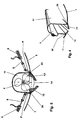
- 1 indicates the hull of a sailing vessel provided with a propulsion system comprising an engine 2 driving a shaft 3 of a propeller 4 with a stern tube and gland 5 which allows said shaft 3 to pass beyond said hull 1 (see Figure 2).
- Shaft 3 incorporates a universal joint 6 (or alternatively a homokinetic joint may be used) and at the extremity thereof close to propeller 4 it is supported in rotation by a smooth bearing 7 through which said shaft 3 can slide longitudinally.
- a universal joint 6 or alternatively a homokinetic joint may be used
- Smooth bearing 7 has formed within its upper part an eye lug 7a provided with an opening to which the end of rod 8 of an operating piston 9, for example a hydraulic piston, is hinged through a pin, piston 9 in turn being secured at 10 to the upper part of the housing 11 in the form of a tunnel formed longitudinally within hull 1 in such a way that said piston 9 can move propeller shaft 3 causing it to rise or fall with respect to hull 1 through appropriate leaktight means (not illustrated), the said shaft pivoting about universal joint 6 between an operating position (illustrated in Figure 2) in which rod 8 is in the extended position and the system is ready to propel the vessel by engine 2, and a position in which it is out of use (see Figure 3) in which rod 8 is retracted within piston 9, causing smooth bearing 7 to rise and as it rises to slide slightly away from propeller 4 and causing shaft 3 to tilt about joint 6 in order to house it in tunnel 11 where it is secured, propeller 4 entering an enlarged part or well 12 formed at the after end of the said tunnel 11 and adequately dimensioned to receive said
- This mechanism for raising and lowering propeller shaft 3 is provided with immobilizing mechanisms (not illustrated) which make it possible to secure it in either of its extreme extended or retracted positions in such a way as to prevent undesired and unforeseen movements of the latter from either of the said positions.
- operating piston 9 fixed to tunnel 11 rod 8 in its extended condition and smooth bearing 7 fulfil the function of a supporting frame to support propeller shaft 3 in rotation while under motor propulsion.
- the overall housing comprising tunnel 11 and well 12 forms a watertight recess in the hull of the vessel and is made, during the construction of the same or subsequently, of the same material as or another material than said hull 1, provided that it is guaranteed to be leaktight in relation to the interior of the vessel.
- said tunnel 11 and/or said well 12 may be provided with adjustment openings for the purpose of maintenance provided with corresponding sealing doors accessible from the interior of the hull.
- Piston 9 may be operated hydraulically by engine 2 or through any other appropriate drive means, for example, an electric pump or other independent power unit 19 (see Figure 1).
- operating piston 9 may be replaced by an equivalent electrical, mechanical or manual operating system supplemented by guide slides or connecting rods (not shown).
- FIG. 4 illustrates diagrammatically and in perspective a fragment of part of tunnel 11 in transverse cross-section along the line A-A in Figure 2.
- Propeller shaft 3 housed in the said tunnel 11 in the condition in which the propulsion system is not in use and the arrangement of sealing doors 13, 13' manufactured from appropriate elastic materials or hinged at points 20 spaced along the edge of the junction with hull 1 in such a way that they can swing back and forth inwardly and outwardly with respect to the said hull to permit passage of the propulsion assembly comprising shaft 3 and propeller 4 in its movements entering and exiting from said hull 1 may be seen in this figure.
- said doors 13, 13' In their closed condition, said doors 13, 13' define a watertight space comprising tunnel 11 and well 12 so that in the condition in which the engine is not in use the hydrodynamic profile of hull 1 is without any appendages belonging to the said propulsion system giving rise to resistance to sailing.
- Said doors 13, 13' may be provided for example with preloaded springs designed to hold them in the closed condition (not shown), the retaining force of which is overcome by the thrust of shaft 3 and propeller 4 as the propulsion system is extended from tunnel 11 and well 12, and when the same is retracted within the hull. In both cases the doors will yield, moving back and forth to permit the passage of shaft 3 and propeller 4 between their two extreme positions.
- said doors 13, 13' may have masses 14 of appropriately shaped lightweight material on their inner surfaces in such a way that when in the closed condition and with the tilting propulsion system housed within the tunnel the free space which can be filled with water is the minimum desirable (see Figure 5).
- each door is activated in order to open or close it by an independent operating mechanism similar for example to piston 9 described above, the rod 8 of which acts on a lever P operating the door hinged to hull 1 at 20.
- the leaktight seal for well 12 designed to house propeller 4 may be achieved through a fairing 15 which is of one piece with the supporting frame, for example, secured to the bottom part of the smooth bearing and designed to press in a sealing relationship against the edges of the opening of said well 12 when shaft 3 and therefore propeller 4 rise towards their housing in the interior of the hull.
- Figure 7 shows another alternative embodiment in which smooth bearing 7 is mounted on two supporting frames 16 hinged thereto at their lower ends at 17 and operated so as to retract into tunnel 11 and well 12 and extend therefrom.
- These two frames 16 may be replaced by individual operating pistons similar to piston 10 in the embodiments previously described. This arrangement is useful when the power transmitted to the propeller shaft requires it.
- the retractable propulsion system according to the invention is supplemented by various safety measures such as electronic microswitches (not shown) intended to make it impossible to bring about retraction of the propulsion system if the operating (forward-astern) control of the propulsion system is not in the off position or, conversely, that is to say the said control cannot be operated in any way forward or astern unless the propulsion system is in its extended position and is secured therein. Otherwise it would be possible to sail under sail with the propulsion system retracted in the hull and with the engine in operation.
- various safety measures such as electronic microswitches (not shown) intended to make it impossible to bring about retraction of the propulsion system if the operating (forward-astern) control of the propulsion system is not in the off position or, conversely, that is to say the said control cannot be operated in any way forward or astern unless the propulsion system is in its extended position and is secured therein. Otherwise it would be possible to sail under sail with the propulsion system retracted in the hull and with the engine
- sealing means between doors 13, 13', 15 and hull 1 so as to form a sealed enclosure for housing the propulsion system within said hull 1, with the possibility of expelling the water lying within it once the doors have been closed, through a bilge pump for example.
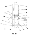
- 101 indicates the hull of a vessel provided with a propulsion system comprising an engine (not shown) which drives a shaft 103 of a propeller 104.
- said shaft 103 is housed within a tunnel 102 provided in the bottom of said hull 101, while propeller 104 is housed in an enlargement located at the after end of said tunnel 102, also within the said hull.
- Propeller shaft 103 is supported in rotation by a supporting bearing 105 which in turn can slip along said shaft 103 when the latter tilts between its positions shown in Figures 8a and 8b.
- Supporting bearing 105 has an eye lug 106 which projects radially therefrom in a vertical direction. At the after end of this eye lug 106 there is an opening to receive a pin 107 acting as a pivot which also passes through two side pieces 108, 108' (of which only one, 108, is illustrated in Figures 8a and 8b) which are of one piece with hinge 109 and also comprise the two members 110, 110' forming the V-shaped supporting frame according to the invention. Said side pieces 108, 108' straddle the said extreme after end of aforesaid eye lug 106.
- shaft 103 includes at least in its forward end, closer to the engine, a universal joint or, alternatively, a homokinetic joint (see Figures 1 to 3) which allows it to tilt between the positions illustrated in Figures 8a and 8b.
- each of the said members 110, 110' has a pair of short robust guide tenons 114, 114' which are intended to act together with said guides 112, 112' respectively as will be seen below.
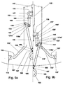
- Figure 9a illustrates the port half of the mechanism according to the invention in its retracted condition, corresponding to the condition illustrated in Figure 8a, and in which all the components forming part of retractable propulsion system 1 of the vessel lie within hull 101.
- Figure 9b shows the actuating, guidance and locking arrangement according to the invention in an intermediate position during its descent, in which position shaft 103 of propeller 104 (not shown in these figures) has begun to descend below the bottom of hull 101 and the articulated parallelogram mechanism which will be described below is at the point at which it begins to unfold through cooperation between tenons 114, 114' and upside-down V guides 112, 112', of which only those designated by 112' are shown in these figures since those indicated by 112 are located outside the plane of the drawing in the direction of the reader.
- FIG 9c this is an illustration of the said articulated parallelogram in its condition of guided descent to the final locked extended position shown in Figure 9d.
- This illustration in Figure 9d in turn corresponds to the condition shown in Figure 8b in which all the equipment constituting the retractable propulsion mechanism for the vessel is in the operating position.
- rod 115 of the actuating mechanism is located in its retracted position and that at its lower end there is attached on one side a horizontal coupling piece 116, the other side of which has pivotably mounted upon it, along axis 117, 117', arms 118, 118' of a length which can be adjusted thanks to the corresponding threaded rod 119, 119' and nut 120, 20' assemblies respectively, the arms of which have pairs of studs 118a, 118a' at their lower ends which are designed to be inserted into corresponding grooves 121a, 121a' made in the heads 121, 121' of frame members 110, 110', the heads of which have a lateral edge 122, 122' in the shape of a wedge.
- rods 118a, 118a' can rotate and move in grooves 121a, 121a' when operating mechanism 115 performs its lowering and raising movements to extend and retract respectively the system of articulated arms according to the invention in a way which is explained below.
- Said frame members 110, 110' are hinged in their lower part at 109 (see also Figures 8a and 8b) in a hinged joint which at its after end has two side members 108, 108' pointing downwards to define a fork which receives after side member 106 of bearing 105 supporting the shaft 103 of the vessel's propeller rotatably about an axis 107.
- this articulation between side pieces 108, 108' and the after end of eye lug 106 about axis 107 allows the upper longitudinal edge of said side piece 106 to follow the movement of hinge 109 in a vertical direction as the latter is raised and lowered through the effect of the action of rod 115 without interfering therewith in such a way that in the retracted positions illustrated in Figure 8a the said upper longitudinal edge of side piece 106 forms an acute angle with the lower part of said hinge 109, while when the mechanism is in its extended condition (see Figure 8b) the said upper longitudinal edge and the lower part of the said hinge are pressed together over their entire length.
- this retracted condition is that used when the vessel is under sail or has problems relating to its draught which make it desirable to retract the propulsion system in order to avoid snagging submerged or similar objects, for example.
- the extension mechanism of rod 115 When it is desired to use the propulsion system through propeller 104, the extension mechanism of rod 115 is activated and this, see Figure 9b, begins its descent in the direction of the arrow and pushes against arms 118, 118' and members 110, 110' of the supporting frame, causing the entire mechanism to descend outside hull 101.
- the abovementioned sealing doors for tunnel 102, housing 111 and the enlargement receiving propeller 104 are activated mechanically, these are already in the open position (not shown). If the doors are of the elastic type or are mounted elastically, the downward movement of the propulsion mechanism itself will move them so that they separate and allow the said mechanism to exit into its operating position.
- Figure 9d shows the final locked position of the articulated system according to the invention.
- the wedge-shaped ends 122, 122' of heads 121, 121' bear against grooves 123, 123' of locking blocks 113, 113' which are of one piece with hull 101.
- the over-centring effect which causes the continued descent of rod 115 once arms 118, 118', 119, 119' of the articulated parallelogram have reached a horizontal position will be seen in this figure, and as a result of this the said arms "spring" into the final locking position illustrated in said Figure 9d, in which it will be seen that coupling piece 116 lies below the horizontal plane represented by the line H and defined by the apices of grooves 123, 123'. Only operation of operating rod 115 in an upward direction will cause the system of articulated arms according to the invention to abandon this locked position.
- the system according to the invention provides a support for the propulsion mechanism for the vessel which overcomes all the disadvantages of the prior art in that it offers a robust and play-free support for the retractable propulsion system.
- the arrangement according to the invention provides, as mentioned above, for the actuation, guidance and locking of the assembly comprising the propeller shaft, the supporting frame and the propeller itself which makes it possible to achieve improved performance of the said assembly in comparison with the prior art.
- the invention is not restricted to this preferred embodiment which has just been described by way of illustration, and it is possible to introduce many changes therein without thereby going beyond the spirit of the invention.
- FIG 10 diagrammatically illustrates an alternative embodiment of the arrangement according to the invention.
- elements similar to those illustrated and described in relation to the embodiment in Figures 8a-b and 9a-d have the same numbers as in those figures.
- propeller shaft 103 which in this case is a telescopic shaft, is provided with an additional universal joint 124, positioned very close to propeller 104, supporting bearing 105 being located between this universal joint 124 and said propeller 104, as may be seen in said Figure 10.
- frame member 110 is joined in a fixed manner by its lower end to said bearing 105 and has at its upper end a head 126 having the configuration shown in the drawing.
- said frame member 110 which in this case has the shape of an inverted isosceles triangle (although this cannot be seen in the drawing), is essentially located in a plane perpendicular to propeller shaft 103, with bearing 105 fixed at its lower apex, said head 126 forming its upper base.
- Frame member 110 is mounted so as to pivot about an axis 125 so that it can tilt between the position illustrated in said Figure 10 and a horizontal position (not shown) on being caused to do this by actuation means which are not shown.
- Said Figure 10 also illustrates locking means of the type of those comprised in the preferred embodiment mentioned above, in this case comprising arms 118, 118' set at an angle, hinged together at 114 and connected at the said hinge point to activation means 115 which fulfil the same function as the activation means in the preferred embodiment described above.
- a head 121 At the free end of said arm 118' there is provided a head 121 with a wedge-shaped edge which is designed to engage in the throat 123 of said head 126 of the supporting frame, bearing against the latter to produce a condition in which it is coupled with locking piece 113 which is of one piece with the hull of the vessel.
- the system of locking by over-centring is achieved in the condition of the propulsion system illustrated in Figure 10 through actuation of actuation means 115 which in bringing about downward displacement of hinge point 114 cause the compass formed by arms 118, 118' to open, causing said wedge 121 to press against groove 123 of said head 126 and to be displaced causing its wedge-shaped edge to bear on corresponding throat 123 of locking piece 113.
- the propulsion system is firmly secured in its operating position in this way.
- wedge 121 separates from head 126 and allows the latter to be in turn separated from locking piece 113.
- the means (not shown) which cause supporting frame 110 to tilt about axis 125 are activated, with the result that the supporting frame moves in the direction indicated by arrow F, lifting propeller 104 upwards as a result of extension of telescopic arm 103 until it reaches a substantially horizontal position in which both supporting frame 110 and bearing 105 positioned in a vertical direction and propeller 104 abutting in approximately a horizontal plane are all housed within the hull of the vessel.
- the retractable propulsion system according to this invention described above can because of its simplicity be incorporated in newly built hulls or in vessels which are already in use.
- the invention also allows for the possibility that the upper part of the housing intended to house the propeller be located above the waterline, as a result of which it can be accessed for the purpose of maintening and repairing the propeller without the need to take the vessel out of the water or to use other costly means such as divers, etc., for example.
- this new propulsion system can also be applied to any type of vessel which is propelled solely by mechanical means where it is necessary or desirable to stow away or protect the said propulsion members in particular circumstances.
Landscapes
- Chemical & Material Sciences (AREA)
- Engineering & Computer Science (AREA)
- Combustion & Propulsion (AREA)
- Mechanical Engineering (AREA)
- Ocean & Marine Engineering (AREA)
- Toys (AREA)
- Transmission Devices (AREA)
- Motor Power Transmission Devices (AREA)
Applications Claiming Priority (4)
| Application Number | Priority Date | Filing Date | Title |
|---|---|---|---|
| ES200202699 | 2002-11-25 | ||
| ES200202699A ES2253007B1 (es) | 2002-11-25 | 2002-11-25 | "sistema retractil para ocultacion de elementos de propulsion para unaembarcacion". |
| ES200301455A ES2270646B1 (es) | 2003-06-20 | 2003-06-20 | Disposicion de accionamiento, guiado y enclavamiento para un sistema retractil de propulsion para una embarcacion. |
| ES200301455 | 2003-06-20 |
Publications (2)
| Publication Number | Publication Date |
|---|---|
| EP1422136A2 true EP1422136A2 (de) | 2004-05-26 |
| EP1422136A3 EP1422136A3 (de) | 2008-01-23 |
Family
ID=32232249
Family Applications (1)
| Application Number | Title | Priority Date | Filing Date |
|---|---|---|---|
| EP03380270A Withdrawn EP1422136A3 (de) | 2002-11-25 | 2003-11-21 | System zum Einziehen von Vortriebskomponenten an Booten |
Country Status (4)
| Country | Link |
|---|---|
| US (1) | US6866553B2 (de) |
| EP (1) | EP1422136A3 (de) |
| AU (1) | AU2003262509A1 (de) |
| NZ (1) | NZ529768A (de) |
Cited By (6)
| Publication number | Priority date | Publication date | Assignee | Title |
|---|---|---|---|---|
| CN102556313A (zh) * | 2011-12-30 | 2012-07-11 | 深圳市海斯比船艇科技股份有限公司 | 可调式表面桨驱动系统及船艇 |
| WO2013122615A1 (en) * | 2011-05-25 | 2013-08-22 | Shoreline Products, Inc. | Emergency drive unit for water vessel |
| AT510993A3 (de) * | 2011-01-13 | 2014-08-15 | Bionx Europ Gmbh | Wasserfahrzeug |
| NL2011498C2 (en) * | 2013-09-25 | 2015-03-30 | Ship Motion Group B V | Retractable propulsion system. |
| WO2021127624A1 (en) * | 2019-12-20 | 2021-06-24 | Carillon Technologies Management Corporation | Unmanned trans-surface vehicle |
| CN116635296A (zh) * | 2020-10-14 | 2023-08-22 | 冯金特里公司 | 船舶的横向推进装置 |
Families Citing this family (2)
| Publication number | Priority date | Publication date | Assignee | Title |
|---|---|---|---|---|
| CN110949622B (zh) * | 2019-11-24 | 2020-11-24 | 杨滋垚 | 一种户外水上用品设备 |
| CN113788131B (zh) * | 2021-10-14 | 2022-09-27 | 中国人民解放军海军工程大学 | 一种水中航行器高级辅助推进系统 |
Citations (3)
| Publication number | Priority date | Publication date | Assignee | Title |
|---|---|---|---|---|
| US4668197A (en) | 1983-06-23 | 1987-05-26 | Salvatore Proto | Retractable auxiliary and emergency propulsion device for small craft |
| US4678440A (en) | 1984-08-22 | 1987-07-07 | Roland Rodrigue | Boat and propulsion system |
| US6056610A (en) | 1995-12-01 | 2000-05-02 | Guy Fontanille | Retractable boat or ship thruster provided with means for preventing pivoting |
Family Cites Families (6)
| Publication number | Priority date | Publication date | Assignee | Title |
|---|---|---|---|---|
| US2151004A (en) * | 1938-04-05 | 1939-03-21 | William L Barclay | Retractable water propeller for airships |
| NL8700535A (nl) * | 1987-03-05 | 1988-10-03 | Meijer Sjoerd | Vaartuig met intrekbare schroef. |
| JPS63287693A (ja) * | 1987-05-20 | 1988-11-24 | Nakashima Puropera Kk | ユニバ−サル型プロペラ装置の舵取り構造 |
| JPH037694A (ja) * | 1989-06-06 | 1991-01-14 | Kazuo Kobayashi | エンジン付きヨット |
| FR2652559B1 (fr) * | 1989-09-29 | 1995-04-28 | Guy Fontanille | Propulseur retractable ou escamotable utilisant un dispositif trapezouidal a rotation deformante engendrant un mouvement rectiligne a l'interieur d'un puits. |
| SE9502213L (sv) * | 1995-06-16 | 1996-06-10 | Motala Verkstad Ab | Anordning vid propellerdrivorgan till marina farkoster |
-
2003
- 2003-11-21 EP EP03380270A patent/EP1422136A3/de not_active Withdrawn
- 2003-11-24 US US10/722,071 patent/US6866553B2/en not_active Expired - Fee Related
- 2003-11-25 AU AU2003262509A patent/AU2003262509A1/en not_active Abandoned
- 2003-11-25 NZ NZ529768A patent/NZ529768A/en not_active IP Right Cessation
Patent Citations (3)
| Publication number | Priority date | Publication date | Assignee | Title |
|---|---|---|---|---|
| US4668197A (en) | 1983-06-23 | 1987-05-26 | Salvatore Proto | Retractable auxiliary and emergency propulsion device for small craft |
| US4678440A (en) | 1984-08-22 | 1987-07-07 | Roland Rodrigue | Boat and propulsion system |
| US6056610A (en) | 1995-12-01 | 2000-05-02 | Guy Fontanille | Retractable boat or ship thruster provided with means for preventing pivoting |
Cited By (10)
| Publication number | Priority date | Publication date | Assignee | Title |
|---|---|---|---|---|
| AT510993A3 (de) * | 2011-01-13 | 2014-08-15 | Bionx Europ Gmbh | Wasserfahrzeug |
| AT510993B1 (de) * | 2011-01-13 | 2015-03-15 | Bionx Europ Gmbh | Wasserfahrzeug |
| WO2013122615A1 (en) * | 2011-05-25 | 2013-08-22 | Shoreline Products, Inc. | Emergency drive unit for water vessel |
| US8790145B2 (en) | 2011-05-26 | 2014-07-29 | Shoreline Products Inc. | Emergency drive unit for water vessel |
| CN102556313A (zh) * | 2011-12-30 | 2012-07-11 | 深圳市海斯比船艇科技股份有限公司 | 可调式表面桨驱动系统及船艇 |
| CN102556313B (zh) * | 2011-12-30 | 2014-09-03 | 深圳市海斯比船艇科技股份有限公司 | 可调式表面桨驱动系统及船艇 |
| NL2011498C2 (en) * | 2013-09-25 | 2015-03-30 | Ship Motion Group B V | Retractable propulsion system. |
| EP2853481A1 (de) | 2013-09-25 | 2015-04-01 | Ship Motion Group B.V. | Einziehbares Antriebssystem |
| WO2021127624A1 (en) * | 2019-12-20 | 2021-06-24 | Carillon Technologies Management Corporation | Unmanned trans-surface vehicle |
| CN116635296A (zh) * | 2020-10-14 | 2023-08-22 | 冯金特里公司 | 船舶的横向推进装置 |
Also Published As
| Publication number | Publication date |
|---|---|
| US6866553B2 (en) | 2005-03-15 |
| EP1422136A3 (de) | 2008-01-23 |
| AU2003262509A1 (en) | 2004-06-10 |
| US20040142610A1 (en) | 2004-07-22 |
| NZ529768A (en) | 2005-11-25 |
Similar Documents
| Publication | Publication Date | Title |
|---|---|---|
| US5152240A (en) | Retractable or storable thruster using a trapezodidal deformably rotatable device producing rectilinear movement inside a well | |
| US5152238A (en) | Split-hinged, winged, self-cradling shallow draft keel for sailing vessel | |
| US5915328A (en) | Boat hull | |
| US10363993B2 (en) | Retractable wing | |
| EP3168137B1 (de) | Ausfahrbares strahlruder | |
| US6866553B2 (en) | Retractable system for stowing away the propulsion components for a vessel | |
| BRPI0516478B1 (pt) | Navio conversível | |
| US20040102107A1 (en) | Wave powered propulsion systems for submarines and quasi-dipped watercrafts | |
| EP2582575B2 (de) | Halbstarres aufblasbares boot mit einem versenkbaren aussenbordmotor | |
| CN114013581A (zh) | 面向减阻与避碰的可变结构型风光波浪能混合驱动无人艇 | |
| EP0175733A1 (de) | Luke für ein boot. | |
| US7434527B2 (en) | Steering and/or stabilising device for motorized watercraft | |
| CN1265075A (zh) | 高速舵 | |
| US5522744A (en) | Retractable marine power drive | |
| CA3071455A1 (en) | Retractable propeller driven pedal system and method of use | |
| US4529386A (en) | Bow motor assembly | |
| US20140162507A1 (en) | Shallow-draft watercraft propulsion and steering apparatus | |
| JPH0481387A (ja) | 水ジェット推進艇 | |
| GB2024734A (en) | A cargo loading and unloading assembly for ships | |
| CN114132443A (zh) | 无人驾驶装备运输舰艇及其航行使用方式 | |
| NL2033273B1 (en) | Retractable propulsion system for a marine vessel | |
| NZ252313A (en) | Marine rudder: mounted in rotatable body so that rudder can be moved vertically | |
| US7044816B2 (en) | Jet drive and retractable rudder fin and filter systems and methods for watercraft | |
| US5671691A (en) | Rudder device | |
| RU239458U1 (ru) | Управляемая потокоразделяющая насадка винторулевой колонки |
Legal Events
| Date | Code | Title | Description |
|---|---|---|---|
| PUAI | Public reference made under article 153(3) epc to a published international application that has entered the european phase |
Free format text: ORIGINAL CODE: 0009012 |
|
| AK | Designated contracting states |
Kind code of ref document: A2 Designated state(s): AT BE BG CH CY CZ DE DK EE ES FI FR GB GR HU IE IT LI LU MC NL PT RO SE SI SK TR |
|
| AX | Request for extension of the european patent |
Extension state: AL LT LV MK |
|
| PUAL | Search report despatched |
Free format text: ORIGINAL CODE: 0009013 |
|
| AK | Designated contracting states |
Kind code of ref document: A3 Designated state(s): AT BE BG CH CY CZ DE DK EE ES FI FR GB GR HU IE IT LI LU MC NL PT RO SE SI SK TR |
|
| AX | Request for extension of the european patent |
Extension state: AL LT LV MK |
|
| AKX | Designation fees paid | ||
| AXX | Extension fees paid |
Extension state: MK Payment date: 20031219 Extension state: LV Payment date: 20031219 Extension state: LT Payment date: 20031219 Extension state: AL Payment date: 20031219 |
|
| STAA | Information on the status of an ep patent application or granted ep patent |
Free format text: STATUS: THE APPLICATION IS DEEMED TO BE WITHDRAWN |
|
| REG | Reference to a national code |
Ref country code: DE Ref legal event code: 8566 |
|
| 18D | Application deemed to be withdrawn |
Effective date: 20080603 |