EP1422075A1 - Instrument d'ecriture - Google Patents
Instrument d'ecriture Download PDFInfo
- Publication number
- EP1422075A1 EP1422075A1 EP03024402A EP03024402A EP1422075A1 EP 1422075 A1 EP1422075 A1 EP 1422075A1 EP 03024402 A EP03024402 A EP 03024402A EP 03024402 A EP03024402 A EP 03024402A EP 1422075 A1 EP1422075 A1 EP 1422075A1
- Authority
- EP
- European Patent Office
- Prior art keywords
- writing
- airtight sleeve
- tubular member
- airtight
- component
- Prior art date
- Legal status (The legal status is an assumption and is not a legal conclusion. Google has not performed a legal analysis and makes no representation as to the accuracy of the status listed.)
- Granted
Links
Images


Classifications
-
- B—PERFORMING OPERATIONS; TRANSPORTING
- B43—WRITING OR DRAWING IMPLEMENTS; BUREAU ACCESSORIES
- B43K—IMPLEMENTS FOR WRITING OR DRAWING
- B43K24/00—Mechanisms for selecting, projecting, retracting or locking writing units
- B43K24/02—Mechanisms for selecting, projecting, retracting or locking writing units for locking a single writing unit in only fully projected or retracted positions
-
- B—PERFORMING OPERATIONS; TRANSPORTING
- B43—WRITING OR DRAWING IMPLEMENTS; BUREAU ACCESSORIES
- B43K—IMPLEMENTS FOR WRITING OR DRAWING
- B43K7/00—Ball-point pens
- B43K7/12—Ball-point pens with retractable ball points
-
- B—PERFORMING OPERATIONS; TRANSPORTING
- B43—WRITING OR DRAWING IMPLEMENTS; BUREAU ACCESSORIES
- B43K—IMPLEMENTS FOR WRITING OR DRAWING
- B43K8/00—Pens with writing-points other than nibs or balls
- B43K8/02—Pens with writing-points other than nibs or balls with writing-points comprising fibres, felt, or similar porous or capillary material
- B43K8/028—Movable closure or gate
Definitions
- the present invention relates generally to writing instruments and, more specifically, to a writing instrument having a writing component containing volatile writing constituents, such as a marker, a water-based ink pen, a water-based ball point pen, a correction pen and a highlighter pen.
- the present invention also relates to a writing instrument in which a writing tip of the writing component can be maintained in an airtight condition when it is not used.
- a writing tip In conventional writing instruments, such as a marker, a writing tip is maintained in an airtight condition so that it will not be dried when it is not used.
- a cap-type writing instrument a cap is detachably attached to the front end of a barrel housing a writing component, and an airtight chamber surrounding the writing tip is formed by attaching the cap.
- a soft material such as a rubber piece is provided in the cap so that it will abut on the writing tip.
- an airtight structure wherein an airtight chamber surrounding the writing tip is disposed at the front portion of a barrel, in which the front end opening portion of the airtight chamber is opened and closed by a biasing member such as a spring so that the airtight chamber is opened when a writing component (e.g., a refill) advances and the airtight chamber is closed when the writing component retracts.
- a writing component e.g., a refill
- conventional writing instruments having an airtight structure for the writing component are available.
- One such writing instrument has a rotating cam-type feeding mechanism disposed in a barrel for moving the writing component forward and backward.
- a rotating cam-type feeding mechanism is disposed in a rear portion of the barrel and has a rotational cam which abuts on a rear end of a writing component, a guide cam which allows the rotational cam to transfer in an axial direction, and an outer cam which is formed on an inner side of the barrel and guides the transfer of the rotational cam.
- the conventional rotating cam-type feeding mechanism is associated with a large number of parts and its manufacture and assembly is complicated.
- the present invention is directed to a writing instrument which overcomes the foregoing drawbacks of the conventional art.
- a writing instrument comprising a cylindrical barrel having an aperture at its front end and a writing component housed in the barrel and having a writing tip and a shoulder located behind the writing tip.
- the barrel and the writing component are relatively movable in an axial direction of the barrel between a writing position at which the writing tip protrudes from the aperture and a housed position at which the writing tip is housed inside the barrel.
- An airtight sleeve is fitted on the front portion of the writing component in such a manner that the airtight sleeve is movable between an advanced position and a retracted position.
- the airtight sleeve has, at a front portion thereof, a bore through which the front portion of the writing component passes.
- An inner raised portion is formed in the airtight sleeve so that when the airtight sleeve is located at the retracted position, the inner raised portion contacts the shoulder of the writing component in an airtight manner. The contact between the inner raised portion of the airtight sleeve and the shoulder of the writing component is disengageable when the airtight sleeve stops at the advanced position.
- a cap plate is pivotally fitted on the airtight sleeve so that the bore of the airtight sleeve may be opened or closed.
- a projecting rib is disposed at a rear side of the cap plate so that when the airtight sleeve moves from the advanced position to the retracted position, the projecting rib abuts on an inner side of the barrel so as to rotate the cap plate in such a direction that the cap plate is pressed against the bore and closes the bore.
- the barrel has a window hole into which the projecting rib enters when the airtight sleeve moves from the retracted position to the advanced position so as to allow the rotational movement of the cap plate to open the bore of the airtight sleeve.
- the writing instrument of the present invention may be constructed so that the barrel is moved relative to the writing component or the writing component is moved relative to the barrel.
- a writing instrument having the rotating-cam type feeding mechanism and the airtight sleeve in the forward portion of the barrel is provided.
- the rotating cam-type feeding mechanism comprises a rotational cam connected to the writing component for undergoing rotational movement and axial movement in the axial direction, an outer cam having a cam groove for guiding movement of the rotational cam in the axial direction, and a guide cam connected to a rear end of the front piece of the tubular body and having a cam element for rotating the rotational cam.
- the airtight sleeve moves together toward the advanced position in such a state that the inner raised portion of the airtight sleeve contacts the shoulder of the writing component.
- the contact between the shoulder of the writing component and the inner raised portion of the airtight sleeve is disengaged.
- the projecting rib confronts the window hole of the barrel, the projecting rib enters into the window hole and, at the same time, the cap plate is opened and the writing tip of the writing component protrudes from the aperture of the barrel. In this state, the writing instrument can be used for writing.
- the inner raised portion of the airtight sleeve contacts the shoulder of the writing component.
- the airtight sleeve then moves together with the writing component toward the retracted position, the cap plate is pressingly fitted to the bore by the projecting rib, the bore of the airtight sleeve is closed, and the periphery of the writing tip is airtightly surrounded, thereby preventing drying of the writing tip.
- the writing instrument of the present invention has a cylindrical barrel having an aperture at its front end and a writing component housed in the barrel.
- the writing component contains volatile writing constituents, such as a marker, a water-based ink pen, a water-based ball point pen, a correction pen and a highlighter pen, and has a writing tip at its front end.
- the barrel and the writing component are relatively movable in an axial direction of the barrel between a writing position, where the writing tip protrudes outwardly from the aperture, and a housed position, where the writing tip is housed inside the barrel.
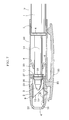
- Figs. 1-7 show a writing instrument according to a first embodiment of the present invention.
- a tubular member in the form of a generally cylindrical barrel 2 is movable in an axial direction relative to a writing component 1.
- the barrel 2 which is generally cap-shaped in this embodiment, extends in an axial direction and is attached to a forward end portion of the writing component 1 (e.g., a refill).
- the barrel 2 is preferably made of a plastic material and moves between a housed position (Fig. 1), where a writing tip 3 of the writing component 1 is housed inside the barrel, and a writing position (Fig. 6 as further described below), where the writing tip 3 protrudes from an aperture 4 formed at the front end of the barrel 2.
- the barrel 2 can be slidingly moved in an axial direction of the writing component 1.
- the barrel may be constructed so that, for example, it moves in an axial direction in a spiral movement by screw coupling the barrel to the writing component (not shown).
- a lock portion 6 On the outer periphery of a large diameter portion 5 of the writing component 1, a lock portion 6 is formed and, correspondingly, engagement portions 7, 8 are disposed in the barrel 2 which engage with the lock portion 6 at the writing position and the housed position, respectively.
- the barrel 2 is held at the housed position by engaging the engagement portion 7 with the lock portion 6 and at the writing position by engaging the engagement portion 8 with the lock portion 6.
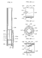
- An airtight sleeve 9 is disposed in the barrel 2 so that it surrounds the writing tip 3.
- the airtight sleeve 9 comprises a tubular member having a generally rectangular-shaped outer surface portion and a generally cylindrical-shaped inner surface portion.
- the airtight sleeve 9 is movable forward and backward between the advanced position and the retracted position in a predetermined range without rotation, and is fitted at a front portion of the writing component 1.
- the airtight sleeve 9 has an inner raised portion 11 adapted to contact a shoulder 10 formed on the writing component 1 in an airtight manner.
- the airtight contact between the inner raised portion 11 of the airtight sleeve 9 and the shoulder 10 of the writing component 1 is designed to be releasable when the airtight sleeve 9 stops at the advanced position. More specifically, the airtight contact between these components is released when the airtight sleeve 9 stops at the advanced position by moving the barrel 2 in such a direction that the writing tip 3 of the writing component 1 protrudes outwardly from the aperture 4 of the barrel 2.
- the airtight sleeve 9 has a bore 12 at a front end portion thereof through which the writing tip 3 of the writing component 1 passes.
- the front side of the bore 12 has a slanted opening edge 13 which slants at an angle of at most about 60°, preferably about 45°, relative to the axis of the barrel 2.
- the airtight sleeve 9 also has a cap plate 15 which is connected to a lower side edge of the bore 12 and which can be opened and closed via an integral plastic hinge 14. As shown in Fig. 4, the hinge 14 extends in the widthwise direction of the cap plate 15 and, as a result, the cap plate 15 is closely and securely contacted with the entire edge of the slanted opening edge 13.
- a projecting rib 17 is disposed on a rear side of the cap plate 15 so that when the airtight sleeve 9 moves toward the retracted position, the projecting rib abuts on an inner side 16 of the barrel 2 to rotate the cap plate 15 and press the cap plate toward the slanted opening edge 13.
- the projecting rib 17 may be formed in any appropriate shape. In the embodiment shown in Fig. 4, the projecting rib 17 is generally triangular-shaped in cross-section with one end of the triangle being connected to a central portion of the cap plate 15. Furthermore, the projecting rib 17 may be formed with a solid or hollow body. If the projecting rib 17 is formed with a hollow body having an appropriate elasticity, as shown in Fig. 4, or formed by using an appropriate elastic piece, the cap plate 15 can be closely contacted to the slanted opening edge 13 with effective elasticity.
- the barrel 2 has a window hole 18 through which the projecting rib 17 enters when the airtight sleeve 9 moves toward the advanced position.
- the writing component 1 has an intermediate portion 19 between the shoulder 10 and the large diameter portion 5.
- the intermediate portion 19 is held elastically by a holding member 20 of the barrel 2.
- the holding member 20 is generally conical-shaped and has slits 21.
- the shoulder 10 of the writing component 1 is pressingly inserted from the large diameter side and passed through it toward the small diameter side of the holding member 20, the barrel 2 can be installed so that it will not separate from the writing component 1.
- the holding member 20 is formed in one piece with the barrel 2.
- the holding member 20 may be a separate component which is integrally connected to the barrel 2.
- the barrel 2 comprises a front piece 22, which has the aperture 4 and the window hole 18, and a barrel main body 23 connected to the front piece 22.
- the airtight sleeve 9 is attached to the front piece 22 of the barrel.
- a guide wall 24 is provided at an inner side of the front piece 22 to guide a side surface of the airtight sleeve 9.
- a guide groove 26 is formed on an the outer side of the front piece 22 for receiving a projection 25 extending from an outer surface of the airtight sleeve 9.
- a flange 27 of the airtight sleeve 9 is adapted to abut with a stop element or stopper 28 formed at a rear end portion of the front piece 22.
- a circumferential groove 30 is formed on the periphery of the front piece 22 for receiving a projection 29 of the barrel main body 23 to prevent detachment of the front piece 22 from the barrel main body 23.
- the front piece 22 also has a longitudinal groove 32 for receiving a projection 31 of the barrel main body 23 to prevent relative rotation between the front piece 22 and the barrel main body 23.
- the barrel main body 23 functions as a cap and also functions as a grip during a writing operation.
- the barrel main body may have a multi-layer structure (not shown) wherein a basal portion is formed with a hard layer and the surface portion is formed with a soft layer by, e.g., two-color molding or an injection molding process.
- a clip 33 is disposed on the outside of the barrel main body 23.
- the barrel 2 is maintained at the housed position where the engagement portion 7 engages with the lock portion 6 of the writing component 1.
- the writing tip 3 is housed in the airtight sleeve 9, the inner raised portion 11 is in contact with the shoulder 10, and the cap plate 15 is pressingly contacted to the slanted opening edge 13 by the projecting rib 17, whereby the inside of the airtight sleeve 9 is kept in an airtight condition and the writing tip 3 is prevented from drying.
- the barrel is maintained at the writing position, and the user can perform a writing operation by gripping the barrel main body 23.
- the engagement force at the lock portion 6 and the engagement portion 8 at this time is set to such a level that it can withstand the writing force.
- the airtight sleeve 9 abuts on the inner side 16 of the barrel 2, the projecting rib 17 comes out of the window hole 18 and is in slidable contact with the inner side 16, and the cap plate 15 is pressed toward the slanted opening edge 13 and, as shown in Fig. 1, the airtight sleeve reaches the retracted position and holds the writing component 1 at the housed position.
- the cap plate of the airtight sleeve is opened, and the writing tip of the writing component can be protruded from the aperture of the barrel at the time of writing. Further, when the barrel is moved forward from the writing position, the cap plate is rotated by the projecting rib and closes the bore of the airtight sleeve, whereby the cap plate surrounds airtightly the periphery of the writing tip and prevent the writing tip from drying.
- the cap plate Since the cap plate is pressed against the slanted opening edge by the projecting rib, the pressing force can be transferred over the entire cap plate and the cap plate can be closely contacted to the opening edge securely and entirely.
- the opening edge is slanted, the rotation of the cap plate can be made small as compared with the case where the opening edge is set at a right angle, and thus the stress exerted on the hinge is low and the durability is improved.
- no special means, such as a spring is required to pressingly fit the cap plate, and the pressing force can always be imparted by means of the projecting rib, the overall structure of the writing instrument is simplified. Furthermore, since the number of parts of the writing instrument is reduced, it is possible to reduce the diameter of the barrel, assembly of the writing instrument is facilitated, and the writing instrument can be obtained economically.
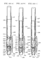
- Figs. 8-14 show another embodiment of the writing instrument according to the present invention in which a writing component 101 is moved in the axial direction relative to a barrel 103.
- Fig. 8 is a partially cutaway view showing the writing instrument of the present invention, and shows a writing instrument 102 having a writing component 101 containing volatile writing constituents such as a marker, a water-based ink pen, a water-based ball point pen, a correction pen and a highlighter pen.
- the writing component 101 is housed in a barrel 103, and the barrel 103 includes a front piece 105 having a barrel main body 103a and an aperture 104 communicating to its front end.
- an inward stepped portion 106 is formed in the barrel 103, and a spring 108 is provided between the inward stepped portion 106 and a stepped portion 107 of the writing component 101 so as to bias the writing component 101 backwardly.
- an outer cam 109 constituting a rotating cam-type feeding mechanism is formed.
- the outer cam 109 has, as conventionally known, a deep cam groove 111a and a shallow cam groove 111b which extend in the axial direction so as to guide the movement of a rotational cam 110 in the axial direction, and an angle-shaped cam element 112 disposed at a front end thereof for rotating the rotational cam 110.
- the outer cam 109 is formed in one piece with an inner surface of the forward portion of the barrel 103.
- the outer cam 109 may be provided as a separate component in the form of a generally cylindrical-shaped body which is integrally connected to the barrel 103.
- the rotational cam 110 is mounted in the barrel 103 for undergoing both rotation and axial movement therein, and is generally cylindrical-shaped with an outer diameter dimensioned to be inserted into the outer cam 109.
- the rotational cam 110 has, on the inner side, a connecting portion 114 which is fitted to a neck portion 113 of the writing component 101 (Fig. 10).
- a projection 115 is provided on the periphery of the rotational cam 110 for engagement with the cam grooves 111a, 111b of the outer cam 109.
- a slanted cam element 116 is provided at a rear end portion of the projection 115 for engagement with the cam element 112 of the outer cam 109.
- a cam element 118 for engagement with a guide cam 117 is provided at a forward end of the rotational cam 110.
- the connecting portion 114 of the rotational cam 110 is elastic so that it can be enlarged so that it can be inserted from a writing tip 119 side to a neck portion 113 of the writing component 101, and when it is inserted up to the neck portion 113, a forward end 121 thereof engages with a flange 120 formed on the writing component 101 and its basal end 123 engages with an intermediate stepped portion 122.
- the rotational cam 110 is loosely fitted to the writing component so that it can be rotated while keeping such a state that it is fitted to the writing component.
- the rotational cam 110 may be a separate component integrally connected to the writing component 101 or it may be formed unitarily with the writing component 101.
- the guide cam 117 is provided at the rear end of the front piece 105 ahead of the rotational cam 110 and has a cam element 124.
- the cam element 118 of the rotational cam 110 abuts on the cam element 124 to rotate the rotational cam 110.
- the cam element 124 confronts the cam element 112 of the outer cam 109 so as to rotate the rotational cam 110 by a predetermined angle. Accordingly, on the periphery of the front piece 105, a circumferential groove 126 (Fig. 11) is formed so that it engages with a latching projection 125 formed in the barrel main body (Fig. 9).
- a projection 128 is provided so that the front piece 105 is connected to the barrel main body 103a in a non-rotatable state.
- the connection between the front piece 105 and the barrel main body 103a can be achieved by appropriate connecting means such as a press-fit connection, an adhesive, a latching pin or the like.
- the rear end of the writing component 101 protrudes from the rear end of the barrel 103 at the housed position.
- the rear end of the barrel 103 may be extended rearwardly so that the rear end of the writing component can be housed in the extended portion of the barrel.
- an appropriate operating member such as a push button or the like may be provided (not shown).
- the projection 115 of the rotational cam 110 separates or disengages from the deep cam groove 111a of the outer cam 109 and abuts on the guide cam 117 to rotate the rotational cam.
- the writing component 101 retracts a little by the spring 108, and the projection 115 engages with the shallow cam groove 111b of the outer cam 109. Accordingly, the writing component 101 is maintained at the writing position in such a state that the writing tip 119 protrudes from the aperture 104.
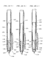
- an airtight sleeve 129 is provided which is fitted to the front portion of the writing component 101 so that it surrounds the writing tip 119 of the writing component.
- the airtight sleeve 129 has a cap plate 130 at its front side of a bore 129a, and when the writing component 101 moves to the writing position, the cap plate 130 is opened and the writing component 119 protrudes from the front end of the barrel. Further, when the writing component moves to the housed position, the cap plate 130 is closed and the writing tip 119 is airtightly held.
- the airtight sleeve 129 has substntially the same function as the airtight sleeve 9 described above with reference to the embodiment of Figs. 1-7. More specifically, the airtight sleeve 129 is disposed at the front portion of the writing component 101 for undergoing forward and rearward movement in a non-rotatable manner so that when the writing component moves to the writing position, the airtight sleeve 129 moves to the advanced position and the cap plate 130 is opened, and when the writing component 101 moves to the housed position, the airtight sleeve 129 moves to the retracted position and the cap plate 130 is closed.
- the airtight sleeve 129 is made of a plastic material and is inserted into the front piece 105 for undergoing forward and rearward movement in such a state that a projection 131 disposed on the outer side is inserted into a guide groove 132 of the front piece 105.
- the airtight sleeve 129 has an inner raised portion 134 which extends from an inner surface thereof and is engageable with a shoulder 133 formed on the writing component 101.
- the inner raised portion 134 engages with the shoulder 133 in an airtight manner when the writing component 101 is located at the housed position (Fig. 14(A)).
- the airtight sleeve 129 moves together with the movement of the writing component 101 when the writing component moves toward the writing position.
- a flange 136 is disposed so that it abuts on a stopper 135 formed on the inner side of the front piece 105. Accordingly, when the airtight sleeve 129 advances up to the position where the flange 136 abuts on the stopper 135 as shown in Fig. 14(B), the airtight sleeve 129 stops at this position and is held at the advanced position.
- the engagement between the inner raised portion 134 and the shoulder 133 is disengaged, and only the writing component advances.
- the cap plate 130 is pivotably provided by an integrally formed hinge 138 at the basal end of a slanted opening edge 137, and at its rear side, a solid projecting rib 139 is formed.
- a sliding surface 140 on which the projecting rib 139 slides and a window hole 141 in which the projecting rib 139 enters are provided.
- the projecting rib 139 slidably contacts the sliding surface 140 and presses the cap plate 130 against the slanted opening edge 137, thereby closing a bore 129a of the airtight sleeve (Fig. 14 (A)).
- the shoulder 133 engages with the inner raised portion 134 during movement (Fig. 14(C)) and the airtight sleeve 129 returns from the advanced position to the retracted position together with movement of the writing component 101.
- the projecting rib 139 disengages from the window hole 141 and slides on the sliding surface 140 (Fig. 14(B)), and the cap plate 130 is rotated by the projecting rib 139 and is thereby pressed against the slanted opening edge 137, whereby the writing tip 119 is airtightly held (Fig. 14(A)).
- a spring (not shown) may be provided between the flange 120 of the writing component 101 and the rear end of the airtight sleeve 129 to bias the airtight sleeve 129 forward.
- the writing instrument 102 since the guide cam which imparts rotation to the rotational cam is integrally formed at the rear portion of the front piece, the number of parts constituting the rotating cam-type feeding mechanism is reduced, thereby providing a writing instrument having a simple construction. Furthermore, since the rotating cam-type feeding mechanism is incorporated into the front portion of the barrel, even if a long writing component is used and incorporated together with the airtight sleeve, the entire writing instrument can be made compact and can be used for a long time since the writing component can be maintained in an airtight condition when it is not used.
Landscapes
- Mechanical Pencils And Projecting And Retracting Systems Therefor, And Multi-System Writing Instruments (AREA)
Applications Claiming Priority (2)
| Application Number | Priority Date | Filing Date | Title |
|---|---|---|---|
| JP2002336246 | 2002-11-20 | ||
| JP2002336246A JP3793968B2 (ja) | 2002-11-20 | 2002-11-20 | 筆記具 |
Publications (2)
| Publication Number | Publication Date |
|---|---|
| EP1422075A1 true EP1422075A1 (fr) | 2004-05-26 |
| EP1422075B1 EP1422075B1 (fr) | 2006-05-24 |
Family
ID=32212084
Family Applications (1)
| Application Number | Title | Priority Date | Filing Date |
|---|---|---|---|
| EP20030024402 Expired - Lifetime EP1422075B1 (fr) | 2002-11-20 | 2003-10-22 | Instrument d'ecriture |
Country Status (3)
| Country | Link |
|---|---|
| EP (1) | EP1422075B1 (fr) |
| JP (1) | JP3793968B2 (fr) |
| DE (1) | DE60305415T2 (fr) |
Cited By (3)
| Publication number | Priority date | Publication date | Assignee | Title |
|---|---|---|---|---|
| FR2907371A1 (fr) * | 2006-10-18 | 2008-04-25 | Bic Soc | Instrument d'ecriture sans capuchon |
| CN104619515A (zh) * | 2012-09-13 | 2015-05-13 | 国誉S&T株式会社 | 书写用具 |
| CN112477471A (zh) * | 2019-09-12 | 2021-03-12 | 东莞司贸文教赠品有限公司 | 一种手推出芯自动翻盖笔 |
Families Citing this family (4)
| Publication number | Priority date | Publication date | Assignee | Title |
|---|---|---|---|---|
| JP4778324B2 (ja) * | 2006-02-06 | 2011-09-21 | ミクロ株式会社 | エアタイト式筆記具 |
| US8393814B2 (en) * | 2009-01-30 | 2013-03-12 | Sanford, L.P. | Retractable instrument having a two stage protraction/retraction sequence |
| FR2986467B1 (fr) * | 2012-02-03 | 2014-02-28 | Bic Soc | Instrument d'ecriture a manchon protecteur de pointe retractable |
| JP2015100987A (ja) | 2013-11-25 | 2015-06-04 | ミクロ株式会社 | 回転式筆記具 |
Citations (2)
| Publication number | Priority date | Publication date | Assignee | Title |
|---|---|---|---|---|
| FR1400077A (fr) * | 1963-11-27 | 1965-05-21 | Pilot Pen Co Ltd | Dispositif de fermeture pour stylo à plume rétractable |
| US5915867A (en) * | 1995-05-26 | 1999-06-29 | Ancos Co., Ltd. | Capless writing tool |
-
2002
- 2002-11-20 JP JP2002336246A patent/JP3793968B2/ja not_active Expired - Lifetime
-
2003
- 2003-10-22 EP EP20030024402 patent/EP1422075B1/fr not_active Expired - Lifetime
- 2003-10-22 DE DE2003605415 patent/DE60305415T2/de not_active Expired - Lifetime
Patent Citations (2)
| Publication number | Priority date | Publication date | Assignee | Title |
|---|---|---|---|---|
| FR1400077A (fr) * | 1963-11-27 | 1965-05-21 | Pilot Pen Co Ltd | Dispositif de fermeture pour stylo à plume rétractable |
| US5915867A (en) * | 1995-05-26 | 1999-06-29 | Ancos Co., Ltd. | Capless writing tool |
Cited By (6)
| Publication number | Priority date | Publication date | Assignee | Title |
|---|---|---|---|---|
| FR2907371A1 (fr) * | 2006-10-18 | 2008-04-25 | Bic Soc | Instrument d'ecriture sans capuchon |
| WO2008050037A2 (fr) * | 2006-10-18 | 2008-05-02 | SOCIéTé BIC | Instrument d'ecriture sans capuchon |
| WO2008050037A3 (fr) * | 2006-10-18 | 2008-07-10 | Bic Soc | Instrument d'ecriture sans capuchon |
| CN104619515A (zh) * | 2012-09-13 | 2015-05-13 | 国誉S&T株式会社 | 书写用具 |
| CN112477471A (zh) * | 2019-09-12 | 2021-03-12 | 东莞司贸文教赠品有限公司 | 一种手推出芯自动翻盖笔 |
| CN112477471B (zh) * | 2019-09-12 | 2024-02-06 | 东莞司贸文教赠品有限公司 | 一种手推出芯自动翻盖笔 |
Also Published As
| Publication number | Publication date |
|---|---|
| JP3793968B2 (ja) | 2006-07-05 |
| EP1422075B1 (fr) | 2006-05-24 |
| DE60305415D1 (de) | 2006-06-29 |
| JP2004167830A (ja) | 2004-06-17 |
| DE60305415T2 (de) | 2006-10-19 |
Similar Documents
| Publication | Publication Date | Title |
|---|---|---|
| US6866436B2 (en) | Writing instrument | |
| US8177447B2 (en) | Slide type writing tools having device for prevent dryness | |
| US10538124B2 (en) | Retractable writing instrument | |
| US4575271A (en) | Writing instrument with movable closure and second sealing means | |
| US6336761B1 (en) | Knock-type writing instrument | |
| US5702193A (en) | Side knock type mechanical pencil | |
| US7527445B2 (en) | Writing instrument | |
| EP1422075B1 (fr) | Instrument d'ecriture | |
| US20050074271A1 (en) | Cartridge type stationery product | |
| CN112172379B (zh) | 带橡皮擦的按动式书写工具 | |
| EP3357707A1 (fr) | Instrument d'écriture présentant une structure d'étanchéité automatique | |
| EP0121113A2 (fr) | Instrument d'écriture | |
| US4884911A (en) | Mechanical pencil with latching chuck actuator | |
| US10214046B2 (en) | Writing instrument having automatic sealing structure | |
| JP3629685B2 (ja) | キャップ式エアタイト筆記具 | |
| AU2017200776B2 (en) | Writing instrument having automatic sealing structure | |
| KR200331308Y1 (ko) | 캡이 내장된 필기구 | |
| JP2575317Y2 (ja) | 触指繰出式シャープペンシル | |
| JP3095985B2 (ja) | 2芯筆記具 | |
| JP2003251983A (ja) | 筆記具 | |
| JP2549410Y2 (ja) | キャップレス筆記具 | |
| JPH0123833Y2 (fr) | ||
| JPH10287088A (ja) | 複式筆記具 | |
| JP2566103Y2 (ja) | 複式筆記具 | |
| JPH09254586A (ja) | 複式筆記具 |
Legal Events
| Date | Code | Title | Description |
|---|---|---|---|
| PUAI | Public reference made under article 153(3) epc to a published international application that has entered the european phase |
Free format text: ORIGINAL CODE: 0009012 |
|
| AK | Designated contracting states |
Kind code of ref document: A1 Designated state(s): AT BE BG CH CY CZ DE DK EE ES FI FR GB GR HU IE IT LI LU MC NL PT RO SE SI SK TR |
|
| AX | Request for extension of the european patent |
Extension state: AL LT LV MK |
|
| 17P | Request for examination filed |
Effective date: 20040622 |
|
| 17Q | First examination report despatched |
Effective date: 20040727 |
|
| AKX | Designation fees paid |
Designated state(s): CH DE FR GB IT LI |
|
| GRAP | Despatch of communication of intention to grant a patent |
Free format text: ORIGINAL CODE: EPIDOSNIGR1 |
|
| GRAS | Grant fee paid |
Free format text: ORIGINAL CODE: EPIDOSNIGR3 |
|
| GRAA | (expected) grant |
Free format text: ORIGINAL CODE: 0009210 |
|
| AK | Designated contracting states |
Kind code of ref document: B1 Designated state(s): CH DE FR GB IT LI |
|
| PG25 | Lapsed in a contracting state [announced via postgrant information from national office to epo] |
Ref country code: IT Free format text: LAPSE BECAUSE OF FAILURE TO SUBMIT A TRANSLATION OF THE DESCRIPTION OR TO PAY THE FEE WITHIN THE PRESCRIBED TIME-LIMIT;WARNING: LAPSES OF ITALIAN PATENTS WITH EFFECTIVE DATE BEFORE 2007 MAY HAVE OCCURRED AT ANY TIME BEFORE 2007. THE CORRECT EFFECTIVE DATE MAY BE DIFFERENT FROM THE ONE RECORDED. Effective date: 20060524 |
|
| REG | Reference to a national code |
Ref country code: GB Ref legal event code: FG4D |
|
| REG | Reference to a national code |
Ref country code: CH Ref legal event code: EP |
|
| REF | Corresponds to: |
Ref document number: 60305415 Country of ref document: DE Date of ref document: 20060629 Kind code of ref document: P |
|
| REG | Reference to a national code |
Ref country code: CH Ref legal event code: NV Representative=s name: SCHMAUDER & PARTNER AG PATENTANWALTSBUERO |
|
| ET | Fr: translation filed | ||
| PLBE | No opposition filed within time limit |
Free format text: ORIGINAL CODE: 0009261 |
|
| STAA | Information on the status of an ep patent application or granted ep patent |
Free format text: STATUS: NO OPPOSITION FILED WITHIN TIME LIMIT |
|
| 26N | No opposition filed |
Effective date: 20070227 |
|
| REG | Reference to a national code |
Ref country code: CH Ref legal event code: PCAR Free format text: SCHMAUDER & PARTNER AG PATENT- UND MARKENANWAELTE VSP;ZWAENGIWEG 7;8038 ZUERICH (CH) |
|
| REG | Reference to a national code |
Ref country code: FR Ref legal event code: PLFP Year of fee payment: 13 |
|
| REG | Reference to a national code |
Ref country code: FR Ref legal event code: PLFP Year of fee payment: 14 |
|
| REG | Reference to a national code |
Ref country code: FR Ref legal event code: PLFP Year of fee payment: 15 |
|
| REG | Reference to a national code |
Ref country code: FR Ref legal event code: PLFP Year of fee payment: 16 |
|
| PGFP | Annual fee paid to national office [announced via postgrant information from national office to epo] |
Ref country code: IT Payment date: 20201030 Year of fee payment: 18 Ref country code: GB Payment date: 20201023 Year of fee payment: 18 Ref country code: FR Payment date: 20201023 Year of fee payment: 18 Ref country code: CH Payment date: 20201023 Year of fee payment: 18 Ref country code: DE Payment date: 20201023 Year of fee payment: 18 |
|
| REG | Reference to a national code |
Ref country code: DE Ref legal event code: R119 Ref document number: 60305415 Country of ref document: DE |
|
| REG | Reference to a national code |
Ref country code: CH Ref legal event code: PL |
|
| GBPC | Gb: european patent ceased through non-payment of renewal fee |
Effective date: 20211022 |
|
| PG25 | Lapsed in a contracting state [announced via postgrant information from national office to epo] |
Ref country code: GB Free format text: LAPSE BECAUSE OF NON-PAYMENT OF DUE FEES Effective date: 20211022 Ref country code: DE Free format text: LAPSE BECAUSE OF NON-PAYMENT OF DUE FEES Effective date: 20220503 |
|
| PG25 | Lapsed in a contracting state [announced via postgrant information from national office to epo] |
Ref country code: LI Free format text: LAPSE BECAUSE OF NON-PAYMENT OF DUE FEES Effective date: 20211031 Ref country code: CH Free format text: LAPSE BECAUSE OF NON-PAYMENT OF DUE FEES Effective date: 20211031 |
|
| PG25 | Lapsed in a contracting state [announced via postgrant information from national office to epo] |
Ref country code: FR Free format text: LAPSE BECAUSE OF NON-PAYMENT OF DUE FEES Effective date: 20211031 |
|
| PG25 | Lapsed in a contracting state [announced via postgrant information from national office to epo] |
Ref country code: IT Free format text: LAPSE BECAUSE OF NON-PAYMENT OF DUE FEES Effective date: 20211022 |