EP1422011B1 - Schweissen-Leistungsversorgungvorrichtung und -verfahren mit einer Dämpfungschaltung - Google Patents
Schweissen-Leistungsversorgungvorrichtung und -verfahren mit einer Dämpfungschaltung Download PDFInfo
- Publication number
- EP1422011B1 EP1422011B1 EP03022989A EP03022989A EP1422011B1 EP 1422011 B1 EP1422011 B1 EP 1422011B1 EP 03022989 A EP03022989 A EP 03022989A EP 03022989 A EP03022989 A EP 03022989A EP 1422011 B1 EP1422011 B1 EP 1422011B1
- Authority
- EP
- European Patent Office
- Prior art keywords
- switches
- freewheeling
- welding
- snubber
- type power
- Prior art date
- Legal status (The legal status is an assumption and is not a legal conclusion. Google has not performed a legal analysis and makes no representation as to the accuracy of the status listed.)
- Expired - Lifetime
Links
- 238000005493 welding type Methods 0.000 title claims description 39
- 238000000034 method Methods 0.000 title claims description 12
- 239000003990 capacitor Substances 0.000 claims description 32
- 238000011084 recovery Methods 0.000 claims description 14
- 230000000087 stabilizing effect Effects 0.000 claims 4
- 230000001131 transforming effect Effects 0.000 claims 2
- 238000003466 welding Methods 0.000 description 5
- 238000010586 diagram Methods 0.000 description 3
- 238000012986 modification Methods 0.000 description 3
- 230000004048 modification Effects 0.000 description 3
- 230000008859 change Effects 0.000 description 2
- 238000010438 heat treatment Methods 0.000 description 2
- 230000008569 process Effects 0.000 description 2
- 241001676573 Minium Species 0.000 description 1
- 230000002411 adverse Effects 0.000 description 1
- 230000007423 decrease Effects 0.000 description 1
- 230000001419 dependent effect Effects 0.000 description 1
- 235000019800 disodium phosphate Nutrition 0.000 description 1
- 230000000694 effects Effects 0.000 description 1
- 239000003381 stabilizer Substances 0.000 description 1
- 230000007704 transition Effects 0.000 description 1
Images
Classifications
-
- B—PERFORMING OPERATIONS; TRANSPORTING
- B23—MACHINE TOOLS; METAL-WORKING NOT OTHERWISE PROVIDED FOR
- B23K—SOLDERING OR UNSOLDERING; WELDING; CLADDING OR PLATING BY SOLDERING OR WELDING; CUTTING BY APPLYING HEAT LOCALLY, e.g. FLAME CUTTING; WORKING BY LASER BEAM
- B23K9/00—Arc welding or cutting
- B23K9/10—Other electric circuits therefor; Protective circuits; Remote controls
- B23K9/1006—Power supply
- B23K9/1043—Power supply characterised by the electric circuit
- B23K9/1056—Power supply characterised by the electric circuit by using digital means
- B23K9/1062—Power supply characterised by the electric circuit by using digital means with computing means
-
- Y—GENERAL TAGGING OF NEW TECHNOLOGICAL DEVELOPMENTS; GENERAL TAGGING OF CROSS-SECTIONAL TECHNOLOGIES SPANNING OVER SEVERAL SECTIONS OF THE IPC; TECHNICAL SUBJECTS COVERED BY FORMER USPC CROSS-REFERENCE ART COLLECTIONS [XRACs] AND DIGESTS
- Y02—TECHNOLOGIES OR APPLICATIONS FOR MITIGATION OR ADAPTATION AGAINST CLIMATE CHANGE
- Y02P—CLIMATE CHANGE MITIGATION TECHNOLOGIES IN THE PRODUCTION OR PROCESSING OF GOODS
- Y02P70/00—Climate change mitigation technologies in the production process for final industrial or consumer products
- Y02P70/10—Greenhouse gas [GHG] capture, material saving, heat recovery or other energy efficient measures, e.g. motor control, characterised by manufacturing processes, e.g. for rolling metal or metal working
Definitions
- the present invention relates generally to the art of welding-type power supplies. More specifically, it relates to a welding-type power supply having a snubber that recovers energy according to the preamble of claim 1 and to a method of providing prodding-type power according to the preamble of claim 19 (see, for example, US-A-6 052 294 ).
- Welding-type power supply includes power supplies that provide welding-type power.
- Welding type power refers to welding, plasma or heating power.
- TIG welding is one well known welding process, and is often performed using a switched power supply, such as a Miller MaxStar 200 ® .
- Switched welding-type power supplies are made with a variety of power topologies and control schemes. Most include a snubber circuit for the switches, that serves to protect switches, such as from voltage spikes.
- Power supplies with snubber circuits e.g. are known from US-A-6,052,294 , US-A-6,115,273 and US patent application US 2002/0047000 A1 , which discloses a DC-bus, an inverter and a switched snubber.
- snubber circuits tend to increase losses and heating. Accordingly, it is desirable to provide a welding-type power supply that includes a snubber circuit that recovers energy that would otherwise not be utilized.
- a welding-type power supply according to claim 1 and a method of providing welding-type power according to claim 19 is defined.
- the inverter is an H-bridge having two current paths in another alternative.
- the plurality of switches includes at least four switches, and the at least one freewheeling switch includes two freewheeling switches, each associated with one of the H-bridge current paths.
- the two freewheeling switches are SCRs and/or the recovery switch is an IGBT in various embodiments.
- the welding-type power supply also includes at least one capacitance circuit connected across the bus, and in parallel with the inverter power circuit.
- a transformer secondary and rectifier is in series with the bus inductor, and the series combination is also in parallel with the capacitance circuit in an alternative.
- a diode is disposed between the snubber capacitor and a rail of the bus in yet another alternative.
- the invention provides for a switched welding-type power supply with a snubber circuit that recovers energy.
- an inverter based welding-type power supply include a snubber circuit that recovers energy from the snubber capacitor when the snubber capacitor voltage exceeds a predetermined voltage (300 volts in one embodiment).
- the energy is recovered using a snubber inductor (i.e. an inductor that forms part of the snubber circuit) in series with a switch.
- the switch When the switch is on, it completes a circuit including the snubber inductor, the switch, a snubber capacitor (i.e., a capacitor that is part of the snubber circuit), the "ON" leg of the inverter bridge, and the output.
- a snubber capacitor i.e., a capacitor that is part of the snubber circuit
- the switch is turned on when the snubber capacitor voltage exceeds the threshold, and turned off when the voltage drops below the threshold, or another threshold (in the preferred embodiment hysteresis in the comparator circuit provides two thresholds). While the switch is on, current flows through the inductor, recovering energy from the snubber capacitor. When the switch is turned off, energy stored in the inductor is returned to the output through a freewheeling path (until the energy is recovered).
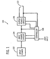
- a welding-type power supply 100 receives input power from an ac source 102 (a dc source may be used in other embodiments) that is provided to an input power circuit 104.
- ac source a dc source may be used in other embodiments
- Input power circuit 104 is preferably consistent with the prior art and includes a rectifier, a half bridge inverter, a transformer and a rectifier. The input is rectified, inverted, transformed and rectified to produce a dc bus.
- an input power circuit that includes a pre-regulator that receives ac or dc, and provides the bus, or transforms the input signal.
- the bus may be created using any method, and is provided to an output power circuit 106, which includes an inverter in the preferred embodiment.
- a controller 108 controls output power circuit 106 (and other controllable stages as needed) to provide welding-type power to an arc 110.
- controller (or control circuit) 108 controls output power circuit 108 to provide a user-selected output is preferably consistent with the prior art, but any general control scheme can be used. (The control specific to the snubber will be described below).
- the magnitude of the output current is controlled using PWM of the input power circuit half-bridge, in a manner known in the prior art, using current feedback from a LEM, and a user setpoint, e.g.
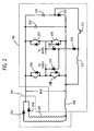
- Transformer/rectifier 104 includes a primary (not shown), a secondary 201 and rectifying diodes 203 and 204.
- An output stabilizer 205 stabilizes (helps maintain an arc current) the output, particularly during polarity transitions with an ac output. These elements cooperate in a manner well known in the art to produce a dc bus that is provided to Power output circuit 106.
- Power output circuit 106 includes, consistent with the prior art, a full H bridge inverter, including switches 206, 207, 208 and 209.
- a capacitor 210 (2.2 ⁇ F in the preferred embodiment) creates a low impedance source to reestablish a welding arc after a polarity change on the output.
- Other embodiments include using a half-bridge or other topologies, including other capacitance circuits, such as split capacitors, parallel capacitor, etc., which are included in the term capacitor.
- the inverter is controlled in a manner known in the art, and an alternating current output is provided by turning on and off switches 206-209 in diagonal pairs. For example, when switches 206 and 209 are on, current flows from the torch to the workpiece. To reverse the current flow, switches 206 and 209 are turned off, and switches 207 and 208 are turned on. The switches are thus alternately turned on and off to create an ac output. A DC output of a given polarity may be provided by turning on only one of the pairs of switches.
- a snubber circuit is connected to the inverter and includes a snubber inductor 212 a recovery switch 213, a snubber capacitor 215 (2.2 ⁇ F in the preferred embodiment), a diode 216, and a pair of steering SCRs 218 and 219, in accordance with the present invention. The operation thereof will be described shortly.
- Inverter switches 206-209 are timed such that as two go off, there is a brief (3-5 ⁇ sec for example) delay before the other pair is turned on.
- bus inductor 205 i.e., the inductor that stabilizes the output
- other system inductances cause a voltage spike to be created on the bus. This spike can adversely effect switches 206-209, and is snubbed (controlled or reduced) by the snubber circuit.
- the energy is recovered and provided to the load.
- recovery switch 213 when the voltage on the snubber capacitor exceeds a threshold (preferably 300 volts) recovery switch 213 is closed. When recovery switch 213 is closed, and either inverter pair is closed, a current path including the bus, the closed inverter switches, the load, inductor 212 and snubber capacitor 215 is closed (or enabled). Thus, current begins to flow in snubber inductor 212.
- a threshold preferably 300 volts
- switch 213 When the snubber capacitor voltage decreases below 300 volts, switch 213 is opened, disabling the current path.
- the current flowing through inductor 212 then flows through one of steering or freewheeling SCRs 218 and 219 (other unidirectional switches may be used), so that the current from inductor 212 is provided across the load.
- SCRs and a diode 220 are used so that current does not freewheel without going through the load.
- SCR 218 is associated with the switches 206 and 209 current path
- SCR 219 is associated with the switches 207-208 current path.
- Other switch types are used in alternative embodiments.
- Switch includes a device that at a minium enables a current path.
- Controller 108 receives voltage and current feedback.
- the current feedback is used to control the PWM of input power circuit 104, and voltage feedback is used to control recovery switch 213. (Other control functions use these or other feedback parameters).
- controller 108 includes a comparison circuit that compares a voltage feedback signal (or a function thereof, such as dv/dt, V*V, the integral of V, etc.) to a signal representative of a threshold.
- the threshold may be factory or user set, or change with the process.
- the various control aspects may be dependent or independent of one another. they may be controlled by a single or multiple controllers, on one or more boards.
- Comparison circuit includes any digital, analog, or other circuit that compares two or more values.
- Controller, or control circuit includes digital and analog circuitry, discrete or integrated circuitry, microprocessors, DSPs, etc., and software, hardware and firmware, located on one or more boards, used to control a device such as a power supply.
- the invention may be implemented using the snubber circuit in other topologies, other stages of a welding-type power supply, or in other applications.
Landscapes
- Engineering & Computer Science (AREA)
- Theoretical Computer Science (AREA)
- Physics & Mathematics (AREA)
- Plasma & Fusion (AREA)
- Mechanical Engineering (AREA)
- Inverter Devices (AREA)
- Arc Welding Control (AREA)
- Rectifiers (AREA)
- Dc-Dc Converters (AREA)
- Generation Of Surge Voltage And Current (AREA)
Claims (22)
- Schweißstromversorgung zum Bereitstellen von Schweißstrom, umfassend:Umrichtermittel (206, 207, 208, 209) zum Wechselrichten eines Busses, um eine Ausgabe bereitzustellen;Schutzmittel (212, 213, 215, 216, 218, 219) zum Schützen des Umrichters;gekennzeichnet durch
ein Stabilisierungsmittel (205) zum Stabilisieren des Busses und der Ausgabe;
wobei die Schutzmittel (212, 213, 215, 216, 218, 219) Mittel (212, 213, 215) zum Wiederherstellen von Energie, wenn eine Schutzkondensatorspannung eine Schwelle übersteigt, und ferner Mittel (218, 219) zum Freilaufenlassen von Strom, wenn sich ein Wiederherstellungsschalter (213) ausschaltet, umfassen;
wobei die Mittel (212, 213, 215) zum Wiederherstellen ein Schaltmittel (213) zum Freigeben und Sperren eines Stromweges umfassen, der eine Schutzinduktivität (212), einen Schutzkondensator (215) und einen Teil der Umrichtermittel (206, 207, 208, 209) umfaßt, und wobei ferner die Mittel (218, 219) zum Freilaufenlassen mindestens einen von mehreren Freilaufschaltern (218, 219) umfassen, wobei ein Freilauf-Stromweg die Schutzinduktivität (212), den mindestens einen Freilaufschalter (218, 219), den Ausgang und mindestens einen von mehreren Umrichterschaltern (206, 207, 208, 209) umfaßt. - Schweißstromversorgung nach Anspruch 1, wobei die Umrichtermittel (206, 207, 208, 209) das Wechselrichten einer H-Brücke mit zwei Stromwegen und mindestens vier Schaltern (206, 207, 208, 209) umfassen, und wobei ferner der mindestens eine Freilaufschalter (218, 219) zwei Freilaufschalter (218, 219) umfaßt, die jeweils mit einem der Stromwege assoziiert sind.
- Schweißstromversorgung nach Anspruch 2, ferner mit einem Mittel (104) zum Transformieren und Gleichrichten eines Wechselstromsignals zur Erzeugung der Busspannung.
- Schweißstromversorgung nach einem der Ansprüche 1 bis 3, wobei die Mittel (212, 213, 215) zum Wiederherstellen einen Stromweg umfassen, der eine Schutzinduktivität (212), einen Schutzkondensator (215), einen Wiederherstellungsschalter (213), den Ausgang und mindestens zwei Umrichterschalter (206, 207, 208, 209) umfaßt.
- Schweißstromversorgung nach Anspruch 1, wobei die Umrichtermittel mehrere Schalter (206, 207, 208, 209) zur Bereitstellung von Ausgangsleistung an dem Ausgang umfassen;
wobei die Schutzmittel (212, 213, 215, 216, 218, 219) vorgesehen sind, um die mehreren Schalter (206, 207, 208, 209) zu schützen; und
wobei die Stromversorgung ferner ein Rückkopplungsmittel (108) zum Bereitstellen eines eine Schutzkondensatorspannung angebenden Signals umfaßt, das mit einem Schutzkondensator (215) verbunden ist; und
ein Mittel (108) zum Steuern des Mittels (213) zum Freigeben und Sperren eines Stromweges und der Mittel (218, 219) zum Freigeben eines Freilaufstroms als Reaktion auf das Signal. - Schweißstromversorgung nach Anspruch 5, wobei die Mittel (206, 207, 208, 209) zum Umrichten mehrere Schalter (206, 207, 208, 209) umfassen und wobei ferner die Mittel (212, 215) zum Speichern, ein Teil der Mittel zum Umrichten (206, 207, 208, 209) und das Mittel (213) zum Freigeben und Sperren einen Stromweg bilden und wobei ferner der Freilaufstromweg das Mittel (212) zum Speichern, mindestens einen Freilaufschalter (218, 219), den Ausgang und den Teil der Mittel (206, 207, 208, 209) zum Umrichten umfaßt.
- Schweißstromversorgung nach Anspruch 5 oder 6, wobei die Mittel (206, 207, 208, 209) zum Umrichten eine H-Brücke mit zwei Stromwegen sind, die mehreren Schalter Mittel (206, 207, 208, 209) mindestens vier Schalter (206, 207, 208, 209) umfassen und der mindestens eine Freilaufschalter (218, 219) zwei Freilaufschalter (218, 219) umfaßt, die jeweils mit einem der Stromwege assoziiert sind.
- Schweißstromversorgung nach einem der Ansprüche 5 bis 7, wobei die beiden Freilaufschalter (218, 219) SCR sind.
- Schweißstromversorgung nach einem der Ansprüche 5 bis 8, ferner mit mindestens einem Mittel (212, 215) zum Speichern von Energie, die an den Bus und parallel mit den Umrichtermitteln (206, 207, 208, 209) geschaltet sind, und ferner mit einer Transformatorsekundärwicklung (201) und einem Gleichrichter (203, 204) in Reihe mit einer Businduktivität (205), wobei die Reihenschaltung parallel zu dem mindestens einem Mittel (212) zum Speichern geschaltet ist.
- Schweißstromversorgung nach Anspruch 9, wobei die Mittel (212, 213, 215) zum Speichern und Wiederherstellen, das Mittel (213) zum Freigeben und Sperren und mindestens zwei der mehreren Schalter (206, 207, 208, 209) einen Stromweg bilden.
- Schweißstromversorgung nach Anspruch 10, wobei das Mittel (213) zum Freigeben und Sperren ein IGBT ist.
- Schweißstromversorgung nach Anspruch 1, wobei die Umrichtermittel eine Umrichterleistungsschaltung (106) umfassen, die einen Bus, mehrere Schalter (206, 207, 208, 209) und einen Ausgang umfaßt;
wobei das Stabilisierungsmittel eine mit dem Umrichter und dem Bus verbundene Businduktivität (205) umfaßt;
wobei die Schutzmittel (212, 213, 215, 216, 218, 219) eine mit den mehreren Schaltern (206, 207, 208, 209) verbundene Schutzschaltung umfassen, die folgendes umfaßt:die Schutzinduktivität (212),den Schutzkondensator (215),den Wiederherstellungsschalter (213), der mit der Schutzinduktivität (212) und dem Schutzkondensator (215) verbunden ist und einen Wiederherstellungsschalter-Steuereingang aufweist, sowie mindestens eine Freilaufschaltung, die die Schutzinduktivität (212) und mindestens einen der Freilaufschalter (218, 219) umfaßt;wobei die Stromversorgung ferner eine Schutzkondensatorspannungsrückkopplungsschaltung (108) umfaßt, die mit dem Schutzkondensator (215) verbunden ist und einen auf eine Schutzkondensatorspannung ansprechenden Schutzkondensatorspannungsrückkopplungsausgang aufweist; und
eine Steuerschaltung (108) mit einer Vergleichsschaltung mit der Schutzkondensatorspannungsrückkopplungsausgabe als eine Eingabe und mit einem mit dem Wiederherstellungsschalter-Steuereingang verbundenen Steuersignal als Ausgabe. - Schweißstromversorgung nach Anspruch 12, wobei der Wiederherstellungsschalter (213), der Schutzkondensator (215), mindestens einer der mehreren Schalter (206, 207, 208, 209), der Ausgang und die Schutzinduktivität (212) einen Stromweg bilden und wobei ferner die Freilaufschaltung die Schutzinduktivität (212), den mindestens einen Freilaufschalter (218, 219), den Ausgang und mindestens einen der mehreren Schalter (206, 207, 208, 209) umfaßt.
- Schweißstromversorgung nach Anspruch 12 oder 13, wobei der Umrichter eine H-Brücke mit zwei Stromwegen ist, die mehreren Schalter (206, 207, 208, 209) mindestens vier Schalter (206, 207, 208, 209) umfassen und der mindestens eine Freilaufschalter (218, 219) zwei Freilaufschalter (218, 219) umfaßt, die jeweils mit einem der Stromwege assoziiert sind.
- Schweißstromversorgung nach Anspruch 14, wobei die beiden Freilaufschalter (218, 219) unidirektionale Schalter sind.
- Schweißstromversorgung nach einem der Ansprüche 12 bis 15, ferner mit mindestens einer Kapazitätsschaltung (210, 215), die an den Bus parallel mit der Umrichter-Leistungsschaltung (106) geschaltet ist, und einer Transformatorsekundärwicklung (201) und einem Gleichrichter (203, 204) in Reihe mit der Businduktivität (205), wobei die Reihenschaltung parallel mit der Kapazitätsschaltung geschaltet ist.
- Schweißstromversorgung nach einem der Ansprüche 12 bis 16, ferner mit einer zwischen dem Schutzkondensator und einer Schiene des Busses angeordneten Diode (216).
- Schweißstromversorgung nach einem der Ansprüche 12 bis 17, wobei der Wiederherstellungsschalter (213) ein IGBT ist.
- Verfahren zum Bereitstellen von Schweißstrom, mit den folgenden Schritten:Umrichten eines Busses, um eine Ausgabe bereitzustellen;Schützen des Umrichters,dadurch gekennzeichnet, daß das Verfahren ferner die folgenden Schritte umfaßt:Stabilisieren des Busses und des Ausgangs; undwobei das Schützen des Umrichters umfaßt, Energie wiederherzustellen, wenn eine Schutzkondensatorspannung eine Schwelle übersteigt, und den Strom freilaufen zu lassen, wenn ein Wiederherstellungsschalter (213) ausgeschaltet ist;
wobei das Wiederherstellen umfaßt, einen Schalter (213) einzuschalten, wobei der Schalter (213), ein Schutzkondensator (215), mindestens einer von mehreren Umrichterschaltern (206, 207, 208, 209), der Ausgang und eine Schutzinduktivität (212) einen Stromweg bilden und wobei ferner das Freilaufenlassen umfaßt, mindestens einen der mehreren Freilaufschalter (218, 219) einzuschalten, und wobei ferner ein Freilaufstromweg die Schutzinduktivität (212), den mindestens einen Freilaufschalter (218, 219), den Ausgang und mindestens einen von mehreren Umrichterschaltern (206, 207, 208, 209) umfaßt. - Verfahren nach Anspruch 19, wobei das Umrichten umfaßt, eine H-Brücke mit zwei Stromwegen und mindestens vier Schaltern (206, 207, 208, 209) umzurichten und wobei ferner der mindestens eine Freilaufschalter (218, 219) zwei Freilaufschalter (218, 219) umfaßt, die jeweils mit einem der Stromwege assoziiert sind.
- Verfahren nach Anspruch 19 oder 20, ferner mit dem Schritt des Transformierens und Gleichrichtens eines Wechselstromssignals zur Erzeugung der Busspannung.
- Verfahren nach einem der Ansprüche 19 bis 21, wobei das Wiederherstellen umfaßt, einen Stromweg zu bilden, der eine Schutzinduktivität (212), einen Wiederherstellungsschalter (213), einen Schutzkondensator (215), den Ausgang und mindestens einen von mehreren Umrichterschaltern (206, 207, 208, 209) umfaßt.
Applications Claiming Priority (2)
| Application Number | Priority Date | Filing Date | Title |
|---|---|---|---|
| US10/300,211 US6801443B2 (en) | 2002-11-19 | 2002-11-19 | Power supply with snubber circuit |
| US300211 | 2002-11-19 |
Publications (3)
| Publication Number | Publication Date |
|---|---|
| EP1422011A2 EP1422011A2 (de) | 2004-05-26 |
| EP1422011A3 EP1422011A3 (de) | 2006-04-26 |
| EP1422011B1 true EP1422011B1 (de) | 2008-07-02 |
Family
ID=32229864
Family Applications (1)
| Application Number | Title | Priority Date | Filing Date |
|---|---|---|---|
| EP03022989A Expired - Lifetime EP1422011B1 (de) | 2002-11-19 | 2003-10-10 | Schweissen-Leistungsversorgungvorrichtung und -verfahren mit einer Dämpfungschaltung |
Country Status (5)
| Country | Link |
|---|---|
| US (1) | US6801443B2 (de) |
| EP (1) | EP1422011B1 (de) |
| JP (1) | JP4472969B2 (de) |
| CN (1) | CN1301821C (de) |
| DE (1) | DE60321876D1 (de) |
Families Citing this family (17)
| Publication number | Priority date | Publication date | Assignee | Title |
|---|---|---|---|---|
| AU614904B2 (en) * | 1989-07-31 | 1991-09-12 | American Telephone And Telegraph Company | Measuring and controlling the thickness of a coating on a elongated article |
| US6980447B1 (en) | 2004-10-18 | 2005-12-27 | Artesyn Technologies, Inc. | Active snubber circuit for synchronous rectifier |
| US9108263B2 (en) * | 2007-04-30 | 2015-08-18 | Illinois Tool Works Inc. | Welding power source with automatic variable high frequency |
| US9878395B2 (en) * | 2008-03-14 | 2018-01-30 | Illinois Tool Works Inc. | Method for detecting current transfer in a plasma arc |
| CN102484429B (zh) * | 2009-09-14 | 2014-12-17 | 依赛彼公司 | 具有整流电路的逆变器 |
| EP2424112B1 (de) * | 2010-08-23 | 2015-07-01 | ABB Research Ltd | Stromausgleich parallel verbundener Halbleiterkomponenten |
| JP5496038B2 (ja) * | 2010-09-22 | 2014-05-21 | 三菱電機株式会社 | Dc−dcコンバータ |
| US9656340B2 (en) * | 2012-09-24 | 2017-05-23 | Lincoln Global, Inc. | Systems and methods providing low current regulation for AC arc welding processes |
| US10207351B2 (en) | 2013-03-15 | 2019-02-19 | Illinois Tool Works Inc. | Method and apparatus for providing welding power |
| US9431819B2 (en) | 2014-01-31 | 2016-08-30 | Drs Power & Control Technologies, Inc. | Methods and systems of impedance source semiconductor device protection |
| CN104057182B (zh) * | 2014-04-17 | 2016-05-18 | 深圳市瑞凌实业股份有限公司 | 实现双丝三电弧焊接的电源装置 |
| US20170028501A1 (en) * | 2015-07-31 | 2017-02-02 | Illinois Tool Works Inc. | Welding System Having Multiple Weld Outputs |
| US10549374B2 (en) | 2015-12-31 | 2020-02-04 | Illinois Tool Works Inc. | Welding power supply with half bridge |
| JP6157663B1 (ja) * | 2016-02-23 | 2017-07-05 | 日本電気計器検定所 | スナバ回路およびスイッチング回路 |
| US11027358B2 (en) * | 2018-08-31 | 2021-06-08 | Illinois Tool Works | Systems and methods for auto-tuning a GMAW welding process |
| KR102473704B1 (ko) | 2020-05-29 | 2022-12-02 | 엘에스일렉트릭(주) | 고체 절연 스위치 |
| CN113945754B (zh) * | 2021-10-16 | 2024-05-24 | 深圳市卡贝电子技术有限公司 | 一种掉电保护电路及保护方法 |
Family Cites Families (11)
| Publication number | Priority date | Publication date | Assignee | Title |
|---|---|---|---|---|
| GB2026261B (en) * | 1978-07-20 | 1982-08-11 | Marconi Co Ltd | Inverter circuits |
| US4849873A (en) * | 1987-11-05 | 1989-07-18 | Medar, Inc. | Active snubber for an inverter |
| JP2754411B2 (ja) * | 1989-09-20 | 1998-05-20 | 富士電機株式会社 | 電力変換装置のスナバ回路 |
| JP2674341B2 (ja) * | 1991-03-27 | 1997-11-12 | 三菱電機株式会社 | 電力変換装置のスナバ回路 |
| US5923547A (en) * | 1998-01-22 | 1999-07-13 | Lucent Technologies | Snubber circuit for a power converter and method of operation thereof |
| US6115273A (en) * | 1998-07-09 | 2000-09-05 | Illinois Tool Works Inc. | Power converter with low loss switching |
| US6052294A (en) * | 1998-09-14 | 2000-04-18 | Lucent Technologies Inc. | Power supply snubber reset circuit |
| US5986904A (en) * | 1998-11-05 | 1999-11-16 | Lucent Technologies, Inc. | Self-regulating lossless snubber circuit |
| JP3296424B2 (ja) * | 1999-03-08 | 2002-07-02 | サンケン電気株式会社 | 電力変換装置 |
| CN1139176C (zh) * | 1999-06-23 | 2004-02-18 | 浙江大学 | 逆变桥用的无源无损耗缓冲电路 |
| US6329636B1 (en) * | 2000-03-31 | 2001-12-11 | Illinois Tool Works Inc. | Method and apparatus for receiving a universal input voltage in a welding plasma or heating power source |
-
2002
- 2002-11-19 US US10/300,211 patent/US6801443B2/en not_active Expired - Lifetime
-
2003
- 2003-10-10 EP EP03022989A patent/EP1422011B1/de not_active Expired - Lifetime
- 2003-10-10 DE DE60321876T patent/DE60321876D1/de not_active Expired - Lifetime
- 2003-11-14 CN CNB2003101136388A patent/CN1301821C/zh not_active Expired - Fee Related
- 2003-11-19 JP JP2003389380A patent/JP4472969B2/ja not_active Expired - Fee Related
Also Published As
| Publication number | Publication date |
|---|---|
| DE60321876D1 (de) | 2008-08-14 |
| JP2004167603A (ja) | 2004-06-17 |
| JP4472969B2 (ja) | 2010-06-02 |
| US6801443B2 (en) | 2004-10-05 |
| CN1502440A (zh) | 2004-06-09 |
| US20040095788A1 (en) | 2004-05-20 |
| CN1301821C (zh) | 2007-02-28 |
| EP1422011A2 (de) | 2004-05-26 |
| EP1422011A3 (de) | 2006-04-26 |
Similar Documents
| Publication | Publication Date | Title |
|---|---|---|
| EP1422011B1 (de) | Schweissen-Leistungsversorgungvorrichtung und -verfahren mit einer Dämpfungschaltung | |
| US12350767B2 (en) | Welding power supply with half bridge | |
| CA2142776C (en) | Controllable inverter power supply | |
| CA2518125C (en) | Improved three stage power source for electric arc welding | |
| US7049546B2 (en) | Method and apparatus for receiving a universal input voltage in a welding power source | |
| US5991180A (en) | Auxiliary open circuit voltage power supply | |
| US10035212B2 (en) | Method and apparatus for providing welding and auxiliary power | |
| US11148219B2 (en) | Method and apparatus for providing welding power | |
| EP3235115B1 (de) | Verfahren und vorrichtung zur bereitstellung von schweiss- und hilfsstrom | |
| CN115333375A (zh) | 具有交联逆变器电路系统的焊接电力供应器 | |
| CN107078631A (zh) | 用于提供电弧焊机中的电力的包括通量平衡的方法和设备 |
Legal Events
| Date | Code | Title | Description |
|---|---|---|---|
| PUAI | Public reference made under article 153(3) epc to a published international application that has entered the european phase |
Free format text: ORIGINAL CODE: 0009012 |
|
| AK | Designated contracting states |
Kind code of ref document: A2 Designated state(s): AT BE BG CH CY CZ DE DK EE ES FI FR GB GR HU IE IT LI LU MC NL PT RO SE SI SK TR |
|
| AX | Request for extension of the european patent |
Extension state: AL LT LV MK |
|
| PUAL | Search report despatched |
Free format text: ORIGINAL CODE: 0009013 |
|
| AK | Designated contracting states |
Kind code of ref document: A3 Designated state(s): AT BE BG CH CY CZ DE DK EE ES FI FR GB GR HU IE IT LI LU MC NL PT RO SE SI SK TR |
|
| AX | Request for extension of the european patent |
Extension state: AL LT LV MK |
|
| 17P | Request for examination filed |
Effective date: 20060623 |
|
| 17Q | First examination report despatched |
Effective date: 20061020 |
|
| AKX | Designation fees paid |
Designated state(s): DE FR GB IT |
|
| GRAP | Despatch of communication of intention to grant a patent |
Free format text: ORIGINAL CODE: EPIDOSNIGR1 |
|
| RTI1 | Title (correction) |
Free format text: WELDING-TYPE POWER SUPPLY AND METHOD OF PROVIDING WELDING-TYPE POWER WITH SNUBBER CIRCUIT |
|
| GRAS | Grant fee paid |
Free format text: ORIGINAL CODE: EPIDOSNIGR3 |
|
| GRAA | (expected) grant |
Free format text: ORIGINAL CODE: 0009210 |
|
| AK | Designated contracting states |
Kind code of ref document: B1 Designated state(s): DE FR GB IT |
|
| REG | Reference to a national code |
Ref country code: GB Ref legal event code: FG4D |
|
| REF | Corresponds to: |
Ref document number: 60321876 Country of ref document: DE Date of ref document: 20080814 Kind code of ref document: P |
|
| PLBE | No opposition filed within time limit |
Free format text: ORIGINAL CODE: 0009261 |
|
| STAA | Information on the status of an ep patent application or granted ep patent |
Free format text: STATUS: NO OPPOSITION FILED WITHIN TIME LIMIT |
|
| 26N | No opposition filed |
Effective date: 20090403 |
|
| PGFP | Annual fee paid to national office [announced via postgrant information from national office to epo] |
Ref country code: DE Payment date: 20131029 Year of fee payment: 11 |
|
| REG | Reference to a national code |
Ref country code: DE Ref legal event code: R119 Ref document number: 60321876 Country of ref document: DE |
|
| PG25 | Lapsed in a contracting state [announced via postgrant information from national office to epo] |
Ref country code: DE Free format text: LAPSE BECAUSE OF NON-PAYMENT OF DUE FEES Effective date: 20150501 |
|
| REG | Reference to a national code |
Ref country code: FR Ref legal event code: PLFP Year of fee payment: 13 |
|
| PGFP | Annual fee paid to national office [announced via postgrant information from national office to epo] |
Ref country code: GB Payment date: 20151027 Year of fee payment: 13 Ref country code: IT Payment date: 20151026 Year of fee payment: 13 |
|
| PGFP | Annual fee paid to national office [announced via postgrant information from national office to epo] |
Ref country code: FR Payment date: 20151019 Year of fee payment: 13 |
|
| GBPC | Gb: european patent ceased through non-payment of renewal fee |
Effective date: 20161010 |
|
| REG | Reference to a national code |
Ref country code: FR Ref legal event code: ST Effective date: 20170630 |
|
| PG25 | Lapsed in a contracting state [announced via postgrant information from national office to epo] |
Ref country code: FR Free format text: LAPSE BECAUSE OF NON-PAYMENT OF DUE FEES Effective date: 20161102 Ref country code: GB Free format text: LAPSE BECAUSE OF NON-PAYMENT OF DUE FEES Effective date: 20161010 |
|
| PG25 | Lapsed in a contracting state [announced via postgrant information from national office to epo] |
Ref country code: IT Free format text: LAPSE BECAUSE OF NON-PAYMENT OF DUE FEES Effective date: 20161010 |