EP1421892B1 - Vorrichtung zum Regeln der Dampfzufuhr in einem Dampfreinigungsgerät - Google Patents
Vorrichtung zum Regeln der Dampfzufuhr in einem Dampfreinigungsgerät Download PDFInfo
- Publication number
- EP1421892B1 EP1421892B1 EP03104235A EP03104235A EP1421892B1 EP 1421892 B1 EP1421892 B1 EP 1421892B1 EP 03104235 A EP03104235 A EP 03104235A EP 03104235 A EP03104235 A EP 03104235A EP 1421892 B1 EP1421892 B1 EP 1421892B1
- Authority
- EP
- European Patent Office
- Prior art keywords
- steam
- outlet aperture
- hole
- respect
- delivery
- Prior art date
- Legal status (The legal status is an assumption and is not a legal conclusion. Google has not performed a legal analysis and makes no representation as to the accuracy of the status listed.)
- Expired - Lifetime
Links
- 238000012384 transportation and delivery Methods 0.000 title claims abstract description 34
- 238000013020 steam cleaning Methods 0.000 title claims abstract description 9
- 239000007787 solid Substances 0.000 claims abstract description 3
- 230000004913 activation Effects 0.000 claims description 4
- 238000004140 cleaning Methods 0.000 description 8
- 230000007246 mechanism Effects 0.000 description 4
- 230000009471 action Effects 0.000 description 3
- 230000008844 regulatory mechanism Effects 0.000 description 3
- 239000003599 detergent Substances 0.000 description 2
- 239000000203 mixture Substances 0.000 description 2
- 230000001105 regulatory effect Effects 0.000 description 2
- 238000007792 addition Methods 0.000 description 1
- 230000001419 dependent effect Effects 0.000 description 1
- 238000006073 displacement reaction Methods 0.000 description 1
- 230000007257 malfunction Effects 0.000 description 1
- 239000000463 material Substances 0.000 description 1
- 230000013011 mating Effects 0.000 description 1
- 230000004048 modification Effects 0.000 description 1
- 238000012986 modification Methods 0.000 description 1
- 230000000750 progressive effect Effects 0.000 description 1
- XLYOFNOQVPJJNP-UHFFFAOYSA-N water Substances O XLYOFNOQVPJJNP-UHFFFAOYSA-N 0.000 description 1
- 238000003809 water extraction Methods 0.000 description 1
Images



Classifications
-
- A—HUMAN NECESSITIES
- A47—FURNITURE; DOMESTIC ARTICLES OR APPLIANCES; COFFEE MILLS; SPICE MILLS; SUCTION CLEANERS IN GENERAL
- A47L—DOMESTIC WASHING OR CLEANING; SUCTION CLEANERS IN GENERAL
- A47L11/00—Machines for cleaning floors, carpets, furniture, walls, or wall coverings
- A47L11/40—Parts or details of machines not provided for in groups A47L11/02 - A47L11/38, or not restricted to one of these groups, e.g. handles, arrangements of switches, skirts, buffers, levers
- A47L11/408—Means for supplying cleaning or surface treating agents
- A47L11/4086—Arrangements for steam generation
-
- A—HUMAN NECESSITIES
- A47—FURNITURE; DOMESTIC ARTICLES OR APPLIANCES; COFFEE MILLS; SPICE MILLS; SUCTION CLEANERS IN GENERAL
- A47L—DOMESTIC WASHING OR CLEANING; SUCTION CLEANERS IN GENERAL
- A47L11/00—Machines for cleaning floors, carpets, furniture, walls, or wall coverings
- A47L11/34—Machines for treating carpets in position by liquid, foam, or vapour, e.g. by steam
-
- A—HUMAN NECESSITIES
- A47—FURNITURE; DOMESTIC ARTICLES OR APPLIANCES; COFFEE MILLS; SPICE MILLS; SUCTION CLEANERS IN GENERAL
- A47L—DOMESTIC WASHING OR CLEANING; SUCTION CLEANERS IN GENERAL
- A47L11/00—Machines for cleaning floors, carpets, furniture, walls, or wall coverings
- A47L11/40—Parts or details of machines not provided for in groups A47L11/02 - A47L11/38, or not restricted to one of these groups, e.g. handles, arrangements of switches, skirts, buffers, levers
- A47L11/408—Means for supplying cleaning or surface treating agents
- A47L11/4083—Liquid supply reservoirs; Preparation of the agents, e.g. mixing devices
-
- A—HUMAN NECESSITIES
- A47—FURNITURE; DOMESTIC ARTICLES OR APPLIANCES; COFFEE MILLS; SPICE MILLS; SUCTION CLEANERS IN GENERAL
- A47L—DOMESTIC WASHING OR CLEANING; SUCTION CLEANERS IN GENERAL
- A47L11/00—Machines for cleaning floors, carpets, furniture, walls, or wall coverings
- A47L11/40—Parts or details of machines not provided for in groups A47L11/02 - A47L11/38, or not restricted to one of these groups, e.g. handles, arrangements of switches, skirts, buffers, levers
- A47L11/4094—Accessories to be used in combination with conventional vacuum-cleaning devices
-
- B—PERFORMING OPERATIONS; TRANSPORTING
- B08—CLEANING
- B08B—CLEANING IN GENERAL; PREVENTION OF FOULING IN GENERAL
- B08B3/00—Cleaning by methods involving the use or presence of liquid or steam
-
- B—PERFORMING OPERATIONS; TRANSPORTING
- B08—CLEANING
- B08B—CLEANING IN GENERAL; PREVENTION OF FOULING IN GENERAL
- B08B2230/00—Other cleaning aspects applicable to all B08B range
- B08B2230/01—Cleaning with steam
Definitions
- the present invention concerns a regulation device to regulate the delivery of steam in a steam cleaning apparatus, such as for example a vacuum cleaner, an electric brush or similar, wherein a steam generator sends the steam generated, through a pipe, to a functional accessory for cleaning objects and/or surfaces.
- a steam cleaning apparatus such as for example a vacuum cleaner, an electric brush or similar
- a steam generator sends the steam generated, through a pipe, to a functional accessory for cleaning objects and/or surfaces.
- the invention concerns a gripper element of the pipe, wherein both activation means to activate the generator and also regulation means to regulate the quantity of steam emerging from the functional accessory are positioned.
- DE A1 4443795 discloses a steam cleaning apparatus in which a toothed wheel can be rotated in order to linearly move a slide which comprises mating teeth on its rear end; the front end of the slide can penetrate more or less within an aperture in the passage of the flow of the steam so as to regulate the delivery of the steam from the apparatus.
- US-A-5.937.475 discloses a water extraction cleaning machine comprising means for regulating the mixture ratio between the water and detergent.
- the regulating means comprises a knob able to be rotated in order to rotate a disk.
- the disk comprises a plurality of apertures which are differently sized and are able to be selectively aligned to a wall aperture, in order to regulate the amount of detergent which is delivered in the mixture.
- the Applicant has devised and embodied the present invention to overcome such shortcomings of the state of the art and to obtain other advantages.
- One purpose of the present invention is to achieve a regulation device to regulate the delivery of steam which does not oblige the user to momentarily interrupt the cleaning operations in order to act on the regulation means to regulate the delivery, and thus allows to reduce the times required to perform the cleaning operations, and avoids physical effort on the part of the user.
- Another purpose of the present invention is to achieve a regulation device that regulates the quantity of steam delivered without the pipe through which the steam passes being occluded.
- the present invention is applied advantageously, though not exclusively, to a steam cleaning apparatus comprising at least a steam generator unit and a connection pipe that connects the generator unit to a functional accessory for delivering steam.
- the apparatus also comprises a gripper element that allows the user to maneuver the pipe and the functional accessory. Regulation means to regulate the delivery of steam are provided on such gripper element.
- the regulation means comprise a first part solid with the gripper element, and a second part able to be associated with said pipe.
- the first and second part are mounted reciprocally rotatable axially with respect to each other.
- the first part comprises a female element provided with an outlet aperture
- the second part comprises a male element inserted into the female element and provided with at least a inlet aperture for the steam.
- the reciprocal rotation of the second part with respect to the first part is able to determine an angular positioning of the inlet aperture with respect to the outlet aperture so as to define a plurality of reciprocal angular positions of the first part and the second part, to which different deliveries of steam through the outlet aperture correspond.
- the inlet aperture comprises an axial hole, a radial through hole communicating with the axial hole, and a circumferential seating made on a segment of an outer surface of the male element, and able to connect the radial through hole with the outlet aperture of the female element.
- the outlet aperture is made radially with respect to the axial hole of the male element, so that the reciprocal rotation of the two parts defines a first angular position for a minimum delivery of steam, wherein only the circumferential seating cooperates with the outlet aperture, a second angular position for a medium delivery of steam, wherein a part of the circumferential seating and a part of the radial hole cooperate with the outlet aperture, and a third angular position for maximum delivery, wherein only the radial hole cooperates completely with the outlet aperture.
- the inlet aperture comprises three through holes, of which a first hole is arranged coaxial to the male element, and two other holes are arranged on opposite sides with respect to the first hole.
- the outlet aperture comprises an eyelet large enough to coincide always with the first hole and selectively with the two other holes.
- the first part comprises an elastic stop element that cooperates with respective positioning seatings made on the second part.
- Each positioning seating defines a precise angular position of the second part with respect to the first part, so that the various regulations of the steam are pre-determined and easily repeatable.
- the device according to the present invention it is possible to regulate the quantity of steam delivered without occluding the pipe through which the steam passes, which can therefore be made of strong material, thus limiting risks of breakages and malfunctions.
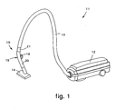
- a regulation device 10 to regulate the delivery of steam according to the present invention is applied to a steam vacuum cleaner 11 of the type comprising a steam generator 12, a connection pipe 13, connected at one end to the generator 12, and a functional accessory, such as for example a brush 14, connected to the free end of the pipe 13, in order to direct the delivery of steam with precision and subsequently suck in the dirt.
- the regulation device 10 comprises a gripper element 15, interposed between the pipe 13 and the brush 14 to allow a user to maneuver the pipe 13 and the brush 14 with extreme ease.
- Both a command button 16 to drive the generator 12 and also a regulation mechanism 17 to regulate the delivery of steam are associated with the gripper element 15 ( figs. 3 and 9 ).
- the mechanism 17 comprises a first part 20 and a second part 21 mounted coaxially with each other and free to rotate one with respect to the other.
- the first part 20 is substantially tubular in shape, is attached to the brush 14 and supports the command button 16, while the second part 21 is also substantially tubular in shape and is connected to the pipe 13.
- the command button 16 is able to be taken selectively into contact with a switch 18 arranged inside the first part 20 and electrically connected to the generator 12.
- the mechanism 17 also comprises a male element 22 and a female element 23, associated rotatably with each other.
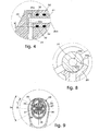
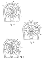
- the female element 23 is mounted on the first part 20 and is provided with an outlet aperture 24 ( figs. 3 to 8 ), which is cylindrical in shape and is arranged substantially vertical, so as to allow the steam to exit.
- the male element 22 is substantially cylindrical in shape, is mounted on the second part 21 and is provided with an inlet aperture 25.
- the inlet aperture 25 comprises a first cylindrical hole 25a made axially on the male element 22, a second through cylindrical hole 25b, with a cross section equivalent to that of the outlet aperture 24, made radially on the male element 22 and communicating with the first cylindrical hole 25a, and a circumferential seating 25c made on an arc of the outer circular surface of the male element 22, and able to put the second cylindrical hole 25b in communication with the outlet aperture 24.
- the circumferential seating 25c ( figs. 4 and 8 ) has a substantially rectangular cross section and a height "h" of some tenths of a millimeter. Such height "h” gradually reduces, until it becomes zero, as the distance from the radial through hole 25b increases angularly, so that the circumferential seating 25c has a variable profile section.
- the second part 21 also comprises, in correspondence with one front end 21a, an elastic stop element 26 ( fig. 9 ), substantially consisting of a pair of balls 27 thrust from opposite sides by a spring 28, and able to cooperate with respective positioning seatings 30 made on an inner surface of the first part 20.
- an elastic stop element 26 substantially consisting of a pair of balls 27 thrust from opposite sides by a spring 28, and able to cooperate with respective positioning seatings 30 made on an inner surface of the first part 20.
- Each of these positioning seatings 30 defines a precise angular position of the second part 21 with respect to the first part 20.
- reference notches 31 On the outer surface of the second part 21 there are reference notches 31 which cooperate with a fixed indicator 33 made on the first part 20, which are able to signal visually to a user the reciprocal position of the cylindrical hole 25b and the circumferential seating 25c, with respect to the outlet aperture 24, and hence the quantity of steam able to be delivered.
- washers 32 provided, of a known type and not described in detail, arranged in proximity with the zones of connection between the first part 20 and the second part 21, and between the female element 23 and the male element 22.
- the regulation device 10 as described heretofore functions as follows.
- part of the second cylindrical hole 25b is also taken into cooperation with the outlet aperture 24, thus increasing the steam passage area, and hence allowing an intermediate delivery of steam.
- the mechanism 17 comprises a first part 120 and a second part 121 mounted coaxially with each other and free to rotate one with respect to the other.
- the first part 120 is substantially tubular in shape, is attached to the brush 14 and supports the command button 16, while the second part 121 is also substantially tubular in shape and is connected to the pipe 13.
- the mechanism 17 also comprises a male element 122 and a female element 123, associated rotatably with each other.
- the female element 123 is mounted on the first part 120 and is provided with an outlet aperture 124 ( figs. 12-14 ) for the delivery of steam.
- the male element 122 is mounted on the second part 121 and is provided with three through holes 125, respectively a central hole 125b and two diametrically opposite lateral holes 125a, 125c, arranged so as to selectively cooperate with the outlet aperture 124.
- the outlet aperture 124 has an elongated form and is shaped so that, in a determinate angular position of the three holes 125a, 125b and 125c, it will coincide with them.
- the first part 120 also comprises ( fig. 11 ), in correspondence with a front surface 120a of the end that cooperates with the second part 121, an elastic stop element 126, substantially consisting of a ball 127 thrust by a spring 128 and able to cooperate with respective positioning seatings 130 made on a front surface 121a of the second part 121.
- Each of these positioning seatings 130 defines a precise angular position of the second part 121 with respect to the first part 120.
- This second form of embodiment of the regulation device 10 according to the invention functions as follows.
- the through holes 125 are taken to an angular position of perfect coincidence with the outlet aperture 124, so as to allow maximum delivery of steam through the brush 14.
- the angle of rotation of the second part 21 or 121 with respect to the first part 20 or 120 is not constrained by any positioning seating 30 or 130, thus allowing a user a wider range of positionings and hence of regulations of the delivery of steam.
- a rigid extension of a known type may be provided between the gripper element 15 and the brush 14 .
Landscapes
- Cleaning By Liquid Or Steam (AREA)
- Cleaning In General (AREA)
- Sampling And Sample Adjustment (AREA)
Claims (12)
- Vorrichtung zum Regeln der Dampfzufuhr in einem Dampfreinigungsgerät (11) mit mindestens einer Dampferzeugereinheit (12), einem Verbindungsrohr (13), das dazu ausgelegt ist, die Erzeugereinheit (12) mit einem funktionellen Anschlussteil (14) zu verbinden, um Dampf zuzuführen, einem Griffelement (15), das dazu ausgelegt ist, einem Benutzer das Bewegen des Rohrs (13) und des funktionellen Anschlussteils (14) zu erlauben, und einer mit dem Griffelement (15) verbundenen Regeleinrichtung (17) zum Regeln der Dampfzufuhr, dadurch gekennzeichnet, dass
die Regeleinrichtung (17) ein mit dem Griffelement (15) festes erstes Rohrteil (20, 120) und ein bezüglich des ersten Rohrteils (20, 120) koaxial befestigtes und frei drehbares zweites Rohrteil (21, 121) aufweist, wobei das zweite Rohrteil (21) mit dem Rohr (13) verbunden ist,
das erste Rohrteil (20, 120) ein mit einer Auslassöffnung (24, 124) versehenes weibliches Element (23, 123) aufweist,
das zweite Rohrteil (21, 121) ein in das weibliche Element (23, 123) gestecktes und mit mindestens einer Einlassöffnung (25, 125) für den Dampf versehenes männliches Element (22, 122) aufweist, und
das Drehen des zweiten Rohrteils (21, 121) relativ zu dem ersten Rohrteil (20, 120) dazu geeignet ist, eine Winkelpositionierung der mindestens einen Einlassöffnung (25, 125) bezüglich der Auslassöffnung (24, 124) zu bestimmen, um eine Vielzahl von Relativwinkelpositionen des ersten Rohrteils (20, 120) und des zweiten Rohrteils (21, 121) zu definieren, denen verschiedene Dampfzufuhrmengen durch die Auslassöffnung (24, 124) entsprechen. - Vorrichtung nach Anspruch 1, dadurch gekennzeichnet, dass
die Einlassöffnung (25) ein axiales Loch (25a), ein mit dem axialen Loch (25a) kommunizierendes radiales Durchgangsloch (25b) und eine auf einem Abschnitt einer Außenfläche des männlichen Elements (22) angebrachte Umfangsbefestigungsfläche (25c) aufweist, die dazu ausgelegt ist, das radiale Durchgangsloch (25b) mit der Auslassöffnung (24) des weiblichen Elements (23) zu verbinden, und
die Auslassöffnung (24) radial bezüglich des axialen Lochs (25a) des männlichen Elements (22) hergestellt ist. - Vorrichtung nach Anspruch 2, dadurch gekennzeichnet, dass
die Umfangsbefestigungsfläche (25c) eine in Übereinstimmung mit dem radialen Durchgangsloch (25b) genau festgelegte Höhe (h) hat, und
die Höhe sich graduell reduziert, bis sie Null wird, wenn der Abstand vom radialen Durchgangsloch (25b) winklig ansteigt, so dass die Umfangsbefestigungsfläche (25c) einen variablen Profilabschnitt aufweist. - Vorrichtung nach Anspruch 2, dadurch gekennzeichnet, dass
in einer ersten Winkelposition, bei minimaler Dampfzufuhr, das männliche Element (22) bezüglich des weiblichen Elements (23) so winkelpositioniert ist, dass nur die Umfangsbefestigungsfläche (25c) mit der Auslassöffnung (24) zusammenwirkt,
in einer zweiten Winkelposition, bei mittlerer Dampfzufuhr, das männliche Element (22) bezüglich des weiblichen Elements (23) so winkelpositioniert ist, dass ein Teil der Umfangsbefestigungsfläche (25c) und ein Teil des radialen Lochs (25b) mit der Auslassöffnung (24) zusammenwirken, und
in einer dritten Winkelposition, bei maximaler Dampfzufuhr, das männliche Element (22) bezüglich des weiblichen Elements (23) so winkelpositioniert ist, dass nur das radiale Loch (25b) mit der Auslassöffnung (24) zusammenwirkt. - Vorrichtung nach Anspruch 4, dadurch gekennzeichnet, dass der Querschnitt des radialen Lochs (25b) im Wesentlichen gleich dem der Auslassöffnung (24) ist.
- Vorrichtung nach Anspruch 1, dadurch gekennzeichnet, dass
die mindestens eine Einlassöffnung (125) drei in das männliche Element (122) gemachte Durchgangslöcher (125a, 125b, 125c) aufweist, von denen ein erstes Loch (125b) in einer mittigen Position und koaxial zum männlichen Element (122) angeordnet ist und zwei weitere Löcher (125a, 125c) an diametral entgegengesetzten Seiten bezüglich des ersten Lochs (125b) angeordnet sind, und
die Auslassöffnung (124) eine Öse aufweist, die groß genug ist, um immer mit dem ersten Loch und wahlweise auch mit den zwei weiteren Löchern (125a, 125c) übereinzustimmen. - Vorrichtung nach Anspruch 6, dadurch gekennzeichnet, dass die drei Durchgangslöcher (125a, 125b, 125c) dazu ausgelegt sind, dass sie durch das Drehen des männlichen Elements (122) relativ zu dem weiblichen Element (123) in eine erste Position minimaler Öffnung, in der nur das erste Loch (125b) mit der Auslassöffnung (124) übereinstimmt, in eine zweite Position mittlerer Öffnung, in der abgesehen vom ersten Loch (125b) die zwei weiteren Löcher (125a, 125c), wenngleich nur teilweise, auch mit der Auslassöffnung (124) übereinstimmen, und in eine dritte Position maximaler Öffnung, in der sowohl das erste Loch (125b) als auch die zwei weiteren Löcher (125a, 125c) vollständig mit der Auslassöffnung (124) übereinstimmen, winkelpositionierbar sind.
- Vorrichtung nach einem der vorhergehenden Ansprüche, dadurch gekennzeichnet, dass das erste Rohrteil (20, 120) ein elastisches Anschlagelement (26, 126) aufweist, das dazu ausgelegt ist, mit den zugehörigen an dem zweiten Rohrteil (21, 121) gebildeten Positionieraufnahmen (30, 130) zusammenzuwirken, wobei jede der Positionieraufnahmen (30, 130) eine präzise Winkelposition des zweiten Rohrteils (21, 121) bezüglich des ersten Rohrteils (20, 120) definiert.
- Vorrichtung nach Anspruch 8, dadurch gekennzeichnet, dass das elastische Anschlagelement (26, 126) mindestens eine mit einer Feder (28, 128) zusammenwirkende Kugel (27, 127) aufweist.
- Vorrichtung nach einem der vorhergehenden Ansprüche, dadurch gekennzeichnet, dass an der Außenfläche des zweiten Rohrteils (21, 121) Referenzkerben (31) sind, die mit einer am ersten Rohrteil (20, 120) angebrachten, zugehörigen festen Markierung (33) zusammenwirken und dazu ausgelegt sind, einem Benutzer die Position der Auslassöffnung (24, 124) relativ zu der Einlassöffnung (25, 125) visuell zu signalisieren.
- Vorrichtung nach einem der vorhergehenden Ansprüche, wobei das Griffelement (15) mit einer Aktivierungseinrichtung (16) für die Erzeugereinheit (12) versehen ist, dadurch gekennzeichnet, dass die Aktivierungseinrichtung einen Steuerknopf (16) aufweist, der einen mit der Erzeugereinheit (12) verbundenen elektrischen Schalter (18) wahlweise steuern kann, um dessen Aktivierung zu bestimmen.
- Vorrichtung nach einem der vorhergehenden Ansprüche, dadurch gekennzeichnet, dass ferner in der Nähe der Verbindungszonen zwischen dem ersten Rohrteil (20, 120) und dem zweiten Rohrteil (21, 121) und zwischen dem weiblichen Element (23, 123) und dem männlichen Element (22, 122) Dichtungsringe (32) angeordnet sind, um eine luftdichte Abdichtung der relativ zueinander drehbaren Rohrteile zu gewährleisten.
Applications Claiming Priority (2)
| Application Number | Priority Date | Filing Date | Title |
|---|---|---|---|
| ITUD20020241 | 2002-11-18 | ||
| IT000241A ITUD20020241A1 (it) | 2002-11-18 | 2002-11-18 | Dispositivo per la regolazione dell'erogazione del vapore |
Publications (2)
| Publication Number | Publication Date |
|---|---|
| EP1421892A1 EP1421892A1 (de) | 2004-05-26 |
| EP1421892B1 true EP1421892B1 (de) | 2010-06-02 |
Family
ID=32211427
Family Applications (1)
| Application Number | Title | Priority Date | Filing Date |
|---|---|---|---|
| EP03104235A Expired - Lifetime EP1421892B1 (de) | 2002-11-18 | 2003-11-17 | Vorrichtung zum Regeln der Dampfzufuhr in einem Dampfreinigungsgerät |
Country Status (5)
| Country | Link |
|---|---|
| EP (1) | EP1421892B1 (de) |
| AT (1) | ATE469594T1 (de) |
| DE (1) | DE60332803D1 (de) |
| ES (1) | ES2345143T3 (de) |
| IT (1) | ITUD20020241A1 (de) |
Families Citing this family (5)
| Publication number | Priority date | Publication date | Assignee | Title |
|---|---|---|---|---|
| US7475448B2 (en) * | 2004-07-02 | 2009-01-13 | Euro-Pro Operating, Llp | Liquid dispensing device and steam cleaner containing same |
| US8935827B2 (en) | 2009-09-25 | 2015-01-20 | Euro-Pro Operating Llc | Steam appliance |
| IT1399520B1 (it) * | 2010-03-30 | 2013-04-19 | T P A Impex Spa | Tubo perfezionato per macchine pulitrici con fluidi ad alta temperatura |
| DE102012110844A1 (de) * | 2012-11-12 | 2014-05-15 | Alfred Kärcher Gmbh & Co. Kg | Handstück für ein Dampfsauggerät |
| GB2537918A (en) * | 2015-04-30 | 2016-11-02 | Ac (Macao Commercial Offshore) Ltd | A tool for a steam cleaning apparatus |
Family Cites Families (5)
| Publication number | Priority date | Publication date | Assignee | Title |
|---|---|---|---|---|
| US4723567A (en) * | 1985-07-19 | 1988-02-09 | Essex Industries, Inc. | Gas flow control valve |
| DE3822793A1 (de) * | 1988-07-06 | 1990-01-11 | Festo Kg | Ventil |
| DE4443795C2 (de) * | 1994-12-08 | 1998-09-10 | Kaercher Gmbh & Co Alfred | Handstück eines Dampfreinigungsgeräts |
| US5937475A (en) * | 1995-11-06 | 1999-08-17 | Bissell Inc. | Water extraction cleaning machine with variable solution mixing valve |
| DE29816208U1 (de) * | 1998-09-09 | 1998-10-22 | Alfred Kärcher GmbH & Co, 71364 Winnenden | Handstück für ein Dampfstrahlgerät |
-
2002
- 2002-11-18 IT IT000241A patent/ITUD20020241A1/it unknown
-
2003
- 2003-11-17 EP EP03104235A patent/EP1421892B1/de not_active Expired - Lifetime
- 2003-11-17 ES ES03104235T patent/ES2345143T3/es not_active Expired - Lifetime
- 2003-11-17 AT AT03104235T patent/ATE469594T1/de not_active IP Right Cessation
- 2003-11-17 DE DE60332803T patent/DE60332803D1/de not_active Expired - Lifetime
Also Published As
| Publication number | Publication date |
|---|---|
| EP1421892A1 (de) | 2004-05-26 |
| ITUD20020241A1 (it) | 2004-05-19 |
| ES2345143T3 (es) | 2010-09-16 |
| DE60332803D1 (de) | 2010-07-15 |
| ATE469594T1 (de) | 2010-06-15 |
Similar Documents
| Publication | Publication Date | Title |
|---|---|---|
| CN107159476B (zh) | 一种通过按键切换出水状态的手持花洒 | |
| US7891047B2 (en) | Steam broom for floor cleaning | |
| EP2910167B1 (de) | Bodenwerkzeug für eine reinigungsvorrichtung | |
| EP4483770B1 (de) | Staubsaugerdüse | |
| EP1421892B1 (de) | Vorrichtung zum Regeln der Dampfzufuhr in einem Dampfreinigungsgerät | |
| US20160214122A1 (en) | Button switching type handheld shower head | |
| ITTO940949A1 (it) | Ugello di spruzzatura, in particolare per apparecchi di lavaggio ad e- levata pressione. | |
| US2921474A (en) | Sprinklers | |
| CN112004608B (zh) | 喷洒设备 | |
| EP1577016A1 (de) | Brausekopf mit kontinuierlicher Waaserstrahlsteuerung und Umschaltvorrichtung dafür | |
| DE19819640A1 (de) | Reinigungsvorrichtung | |
| CN110538731A (zh) | 一种淋浴装置 | |
| KR102505420B1 (ko) | 핸드 비데 장치 | |
| EP1482084A1 (de) | Gewerbliches und halbgewerbliches Dampfbügeleisen | |
| CN107470042B (zh) | 带有可选择的射束成形体的喷淋设备 | |
| CN211175500U (zh) | 一种防误开出水装置 | |
| US3646632A (en) | Indicating means for a belt lifter | |
| WO2016062331A1 (en) | Fluid dispensing device | |
| CN212251301U (zh) | 防误操作的淋浴器把手 | |
| CN110584518B (zh) | 一种可伸缩的淋浴器下出水结构 | |
| KR200157819Y1 (ko) | 청소기의 연장관 | |
| KR100222645B1 (ko) | 청소기의 연장관 | |
| KR100504529B1 (ko) | 진공청소기의 손잡이와 흡입호스의 연결구조체 | |
| JPH067229Y2 (ja) | 水路切換装置 | |
| US2389042A (en) | Suction cleaner |
Legal Events
| Date | Code | Title | Description |
|---|---|---|---|
| PUAI | Public reference made under article 153(3) epc to a published international application that has entered the european phase |
Free format text: ORIGINAL CODE: 0009012 |
|
| AK | Designated contracting states |
Kind code of ref document: A1 Designated state(s): AT BE BG CH CY CZ DE DK EE ES FI FR GB GR HU IE IT LI LU MC NL PT RO SE SI SK TR |
|
| AX | Request for extension of the european patent |
Extension state: AL LT LV MK |
|
| 17P | Request for examination filed |
Effective date: 20041126 |
|
| AKX | Designation fees paid |
Designated state(s): AT BE BG CH CY CZ DE DK EE ES FI FR GB GR HU IE IT LI LU MC NL PT RO SE SI SK TR |
|
| GRAP | Despatch of communication of intention to grant a patent |
Free format text: ORIGINAL CODE: EPIDOSNIGR1 |
|
| GRAS | Grant fee paid |
Free format text: ORIGINAL CODE: EPIDOSNIGR3 |
|
| GRAA | (expected) grant |
Free format text: ORIGINAL CODE: 0009210 |
|
| AK | Designated contracting states |
Kind code of ref document: B1 Designated state(s): AT BE BG CH CY CZ DE DK EE ES FI FR GB GR HU IE IT LI LU MC NL PT RO SE SI SK TR |
|
| REG | Reference to a national code |
Ref country code: GB Ref legal event code: FG4D |
|
| REG | Reference to a national code |
Ref country code: CH Ref legal event code: EP |
|
| REG | Reference to a national code |
Ref country code: IE Ref legal event code: FG4D |
|
| REF | Corresponds to: |
Ref document number: 60332803 Country of ref document: DE Date of ref document: 20100715 Kind code of ref document: P |
|
| REG | Reference to a national code |
Ref country code: ES Ref legal event code: FG2A Ref document number: 2345143 Country of ref document: ES Kind code of ref document: T3 |
|
| REG | Reference to a national code |
Ref country code: NL Ref legal event code: VDEP Effective date: 20100602 |
|
| PG25 | Lapsed in a contracting state [announced via postgrant information from national office to epo] |
Ref country code: SE Free format text: LAPSE BECAUSE OF FAILURE TO SUBMIT A TRANSLATION OF THE DESCRIPTION OR TO PAY THE FEE WITHIN THE PRESCRIBED TIME-LIMIT Effective date: 20100602 |
|
| PG25 | Lapsed in a contracting state [announced via postgrant information from national office to epo] |
Ref country code: SI Free format text: LAPSE BECAUSE OF FAILURE TO SUBMIT A TRANSLATION OF THE DESCRIPTION OR TO PAY THE FEE WITHIN THE PRESCRIBED TIME-LIMIT Effective date: 20100602 Ref country code: FI Free format text: LAPSE BECAUSE OF FAILURE TO SUBMIT A TRANSLATION OF THE DESCRIPTION OR TO PAY THE FEE WITHIN THE PRESCRIBED TIME-LIMIT Effective date: 20100602 Ref country code: AT Free format text: LAPSE BECAUSE OF FAILURE TO SUBMIT A TRANSLATION OF THE DESCRIPTION OR TO PAY THE FEE WITHIN THE PRESCRIBED TIME-LIMIT Effective date: 20100602 |
|
| PG25 | Lapsed in a contracting state [announced via postgrant information from national office to epo] |
Ref country code: CY Free format text: LAPSE BECAUSE OF FAILURE TO SUBMIT A TRANSLATION OF THE DESCRIPTION OR TO PAY THE FEE WITHIN THE PRESCRIBED TIME-LIMIT Effective date: 20100602 Ref country code: GR Free format text: LAPSE BECAUSE OF FAILURE TO SUBMIT A TRANSLATION OF THE DESCRIPTION OR TO PAY THE FEE WITHIN THE PRESCRIBED TIME-LIMIT Effective date: 20100903 |
|
| PG25 | Lapsed in a contracting state [announced via postgrant information from national office to epo] |
Ref country code: NL Free format text: LAPSE BECAUSE OF FAILURE TO SUBMIT A TRANSLATION OF THE DESCRIPTION OR TO PAY THE FEE WITHIN THE PRESCRIBED TIME-LIMIT Effective date: 20100602 Ref country code: EE Free format text: LAPSE BECAUSE OF FAILURE TO SUBMIT A TRANSLATION OF THE DESCRIPTION OR TO PAY THE FEE WITHIN THE PRESCRIBED TIME-LIMIT Effective date: 20100602 |
|
| PG25 | Lapsed in a contracting state [announced via postgrant information from national office to epo] |
Ref country code: SK Free format text: LAPSE BECAUSE OF FAILURE TO SUBMIT A TRANSLATION OF THE DESCRIPTION OR TO PAY THE FEE WITHIN THE PRESCRIBED TIME-LIMIT Effective date: 20100602 Ref country code: RO Free format text: LAPSE BECAUSE OF FAILURE TO SUBMIT A TRANSLATION OF THE DESCRIPTION OR TO PAY THE FEE WITHIN THE PRESCRIBED TIME-LIMIT Effective date: 20100602 Ref country code: BE Free format text: LAPSE BECAUSE OF FAILURE TO SUBMIT A TRANSLATION OF THE DESCRIPTION OR TO PAY THE FEE WITHIN THE PRESCRIBED TIME-LIMIT Effective date: 20100602 Ref country code: CZ Free format text: LAPSE BECAUSE OF FAILURE TO SUBMIT A TRANSLATION OF THE DESCRIPTION OR TO PAY THE FEE WITHIN THE PRESCRIBED TIME-LIMIT Effective date: 20100602 Ref country code: PT Free format text: LAPSE BECAUSE OF FAILURE TO SUBMIT A TRANSLATION OF THE DESCRIPTION OR TO PAY THE FEE WITHIN THE PRESCRIBED TIME-LIMIT Effective date: 20101004 |
|
| PLBE | No opposition filed within time limit |
Free format text: ORIGINAL CODE: 0009261 |
|
| STAA | Information on the status of an ep patent application or granted ep patent |
Free format text: STATUS: NO OPPOSITION FILED WITHIN TIME LIMIT |
|
| PG25 | Lapsed in a contracting state [announced via postgrant information from national office to epo] |
Ref country code: DK Free format text: LAPSE BECAUSE OF FAILURE TO SUBMIT A TRANSLATION OF THE DESCRIPTION OR TO PAY THE FEE WITHIN THE PRESCRIBED TIME-LIMIT Effective date: 20100602 |
|
| 26N | No opposition filed |
Effective date: 20110303 |
|
| REG | Reference to a national code |
Ref country code: DE Ref legal event code: R097 Ref document number: 60332803 Country of ref document: DE Effective date: 20110302 Ref country code: DE Ref legal event code: R097 Ref document number: 60332803 Country of ref document: DE Effective date: 20110303 |
|
| PG25 | Lapsed in a contracting state [announced via postgrant information from national office to epo] |
Ref country code: MC Free format text: LAPSE BECAUSE OF NON-PAYMENT OF DUE FEES Effective date: 20101130 |
|
| REG | Reference to a national code |
Ref country code: CH Ref legal event code: PL |
|
| GBPC | Gb: european patent ceased through non-payment of renewal fee |
Effective date: 20101117 |
|
| PG25 | Lapsed in a contracting state [announced via postgrant information from national office to epo] |
Ref country code: CH Free format text: LAPSE BECAUSE OF NON-PAYMENT OF DUE FEES Effective date: 20101130 Ref country code: LI Free format text: LAPSE BECAUSE OF NON-PAYMENT OF DUE FEES Effective date: 20101130 |
|
| REG | Reference to a national code |
Ref country code: FR Ref legal event code: ST Effective date: 20110801 |
|
| REG | Reference to a national code |
Ref country code: DE Ref legal event code: R119 Ref document number: 60332803 Country of ref document: DE Effective date: 20110601 Ref country code: DE Ref legal event code: R119 Ref document number: 60332803 Country of ref document: DE Effective date: 20110531 |
|
| PG25 | Lapsed in a contracting state [announced via postgrant information from national office to epo] |
Ref country code: FR Free format text: LAPSE BECAUSE OF NON-PAYMENT OF DUE FEES Effective date: 20101130 Ref country code: IE Free format text: LAPSE BECAUSE OF NON-PAYMENT OF DUE FEES Effective date: 20101117 |
|
| PG25 | Lapsed in a contracting state [announced via postgrant information from national office to epo] |
Ref country code: GB Free format text: LAPSE BECAUSE OF NON-PAYMENT OF DUE FEES Effective date: 20101117 |
|
| PG25 | Lapsed in a contracting state [announced via postgrant information from national office to epo] |
Ref country code: HU Free format text: LAPSE BECAUSE OF FAILURE TO SUBMIT A TRANSLATION OF THE DESCRIPTION OR TO PAY THE FEE WITHIN THE PRESCRIBED TIME-LIMIT Effective date: 20101203 Ref country code: BG Free format text: LAPSE BECAUSE OF FAILURE TO SUBMIT A TRANSLATION OF THE DESCRIPTION OR TO PAY THE FEE WITHIN THE PRESCRIBED TIME-LIMIT Effective date: 20100602 Ref country code: LU Free format text: LAPSE BECAUSE OF NON-PAYMENT OF DUE FEES Effective date: 20101117 |
|
| PG25 | Lapsed in a contracting state [announced via postgrant information from national office to epo] |
Ref country code: TR Free format text: LAPSE BECAUSE OF FAILURE TO SUBMIT A TRANSLATION OF THE DESCRIPTION OR TO PAY THE FEE WITHIN THE PRESCRIBED TIME-LIMIT Effective date: 20100602 |
|
| PG25 | Lapsed in a contracting state [announced via postgrant information from national office to epo] |
Ref country code: DE Free format text: LAPSE BECAUSE OF NON-PAYMENT OF DUE FEES Effective date: 20110531 |
|
| PG25 | Lapsed in a contracting state [announced via postgrant information from national office to epo] |
Ref country code: BG Free format text: LAPSE BECAUSE OF FAILURE TO SUBMIT A TRANSLATION OF THE DESCRIPTION OR TO PAY THE FEE WITHIN THE PRESCRIBED TIME-LIMIT Effective date: 20100902 |
|
| PGFP | Annual fee paid to national office [announced via postgrant information from national office to epo] |
Ref country code: ES Payment date: 20191212 Year of fee payment: 17 Ref country code: IT Payment date: 20191122 Year of fee payment: 17 |
|
| PG25 | Lapsed in a contracting state [announced via postgrant information from national office to epo] |
Ref country code: IT Free format text: LAPSE BECAUSE OF NON-PAYMENT OF DUE FEES Effective date: 20201117 |
|
| REG | Reference to a national code |
Ref country code: ES Ref legal event code: FD2A Effective date: 20220202 |
|
| PG25 | Lapsed in a contracting state [announced via postgrant information from national office to epo] |
Ref country code: ES Free format text: LAPSE BECAUSE OF NON-PAYMENT OF DUE FEES Effective date: 20201118 |