EP1421711B1 - Systemes et techniques de commande de puissance - Google Patents
Systemes et techniques de commande de puissance Download PDFInfo
- Publication number
- EP1421711B1 EP1421711B1 EP02761494A EP02761494A EP1421711B1 EP 1421711 B1 EP1421711 B1 EP 1421711B1 EP 02761494 A EP02761494 A EP 02761494A EP 02761494 A EP02761494 A EP 02761494A EP 1421711 B1 EP1421711 B1 EP 1421711B1
- Authority
- EP
- European Patent Office
- Prior art keywords
- power
- channel
- power control
- set point
- received transmission
- Prior art date
- Legal status (The legal status is an assumption and is not a legal conclusion. Google has not performed a legal analysis and makes no representation as to the accuracy of the status listed.)
- Expired - Lifetime
Links
Images


Classifications
-
- H—ELECTRICITY
- H04—ELECTRIC COMMUNICATION TECHNIQUE
- H04W—WIRELESS COMMUNICATION NETWORKS
- H04W52/00—Power management, e.g. TPC [Transmission Power Control], power saving or power classes
- H04W52/04—TPC
- H04W52/18—TPC being performed according to specific parameters
- H04W52/28—TPC being performed according to specific parameters using user profile, e.g. mobile speed, priority or network state, e.g. standby, idle or non transmission
- H04W52/282—TPC being performed according to specific parameters using user profile, e.g. mobile speed, priority or network state, e.g. standby, idle or non transmission taking into account the speed of the mobile
-
- H—ELECTRICITY
- H04—ELECTRIC COMMUNICATION TECHNIQUE
- H04W—WIRELESS COMMUNICATION NETWORKS
- H04W52/00—Power management, e.g. TPC [Transmission Power Control], power saving or power classes
- H04W52/04—TPC
- H04W52/06—TPC algorithms
- H04W52/16—Deriving transmission power values from another channel
-
- H—ELECTRICITY
- H04—ELECTRIC COMMUNICATION TECHNIQUE
- H04W—WIRELESS COMMUNICATION NETWORKS
- H04W28/00—Network traffic management; Network resource management
- H04W28/02—Traffic management, e.g. flow control or congestion control
- H04W28/04—Error control
-
- H—ELECTRICITY
- H04—ELECTRIC COMMUNICATION TECHNIQUE
- H04W—WIRELESS COMMUNICATION NETWORKS
- H04W52/00—Power management, e.g. TPC [Transmission Power Control], power saving or power classes
- H04W52/04—TPC
- H04W52/18—TPC being performed according to specific parameters
- H04W52/20—TPC being performed according to specific parameters using error rate
-
- H—ELECTRICITY
- H04—ELECTRIC COMMUNICATION TECHNIQUE
- H04W—WIRELESS COMMUNICATION NETWORKS
- H04W52/00—Power management, e.g. TPC [Transmission Power Control], power saving or power classes
- H04W52/04—TPC
- H04W52/18—TPC being performed according to specific parameters
- H04W52/26—TPC being performed according to specific parameters using transmission rate or quality of service QoS [Quality of Service]
-
- H—ELECTRICITY
- H04—ELECTRIC COMMUNICATION TECHNIQUE
- H04W—WIRELESS COMMUNICATION NETWORKS
- H04W52/00—Power management, e.g. TPC [Transmission Power Control], power saving or power classes
- H04W52/04—TPC
- H04W52/30—TPC using constraints in the total amount of available transmission power
- H04W52/32—TPC of broadcast or control channels
- H04W52/325—Power control of control or pilot channels
-
- H—ELECTRICITY
- H04—ELECTRIC COMMUNICATION TECHNIQUE
- H04W—WIRELESS COMMUNICATION NETWORKS
- H04W52/00—Power management, e.g. TPC [Transmission Power Control], power saving or power classes
- H04W52/04—TPC
- H04W52/38—TPC being performed in particular situations
-
- H—ELECTRICITY
- H04—ELECTRIC COMMUNICATION TECHNIQUE
- H04W—WIRELESS COMMUNICATION NETWORKS
- H04W52/00—Power management, e.g. TPC [Transmission Power Control], power saving or power classes
- H04W52/04—TPC
- H04W52/38—TPC being performed in particular situations
- H04W52/44—TPC being performed in particular situations in connection with interruption of transmission
Definitions
- the present invention relates to communications systems, and more specifically, to systems and techniques for controlling transmission power in a wireless communications system.
- Modern communications systems are designed to allow multiple users to access a common communications medium.
- Numerous multiple-access techniques are known in the art, such as time division multiple-access (TDMA), frequency division multiple-access (FDMA), space division multiple-access, polarization division multiple-access, code division multiple-access (CDMA), and other similar multi-access techniques.
- the multiple-access concept is a channel allocation methodology which allows multiple user access to a common communications link.
- the channel allocations can take on various forms depending on the specific multi-access technique.
- FDMA systems the total frequency spectrum is divided into a number of smaller sub-bands and each user is given its own sub-band to access the communications link.
- each user is given the entire frequency spectrum during periodically recurring time slots.
- each user is given the entire frequency spectrum for all of the time but distinguishes its transmission through the use of a unique code.
- techniques to reduce mutual interference between multiple users are often utilized to increase user capacity.
- power control techniques can be employed to limit the transmission power of each user to that necessary to achieve a desired quality of service. This approach ensures that each user transmits only the minimum power necessary, but no higher, thereby making the smallest possible contribution to the total noise seen by other users.
- the desired quality of service is based on one or more quality parameters of the voice or data transmissions. However, when voice and data transmissions are not present, it is desirable to optimize the transmission power of each user in other ways. This optimization of the transmission power should be done in a way that does not degrade the quality of service when voice or data transmissions reoccur.
- Nontel discloses a signaling method for controlling unnecessary power increases and call drop during discontinuous transmission (DTX) mode of a frame-based transmission system.
- the signaling method as comprising the steps of (1) detecting, at a receiver end of the transmission system a status of a transmitted frame indicating one of two possible transmission modes including (a) when a gating-off of the traffic channel occurs, and (b) when no gating-off of traffic occurs and normal traffic is being transmitted, and (2) controlling a change in the receiver target bit energy to noise spectrum density ratio Eb/No in response to the detection step so that a receiver target Eb/No is increased only when the detecting step does not indicate a gating-off of traffic has occurred.
- WO Publication No. 2000/48335 discloses a power control method for a mobile station which has at least one frame including a data transmission duration where data is transmitted at a first frequency, and a data transmission-off duration where a second frequency is searched to perform an inter-frequency handoff to the second frequency.
- Samsung teaches the transmission power at the data transmission duration is increased to compensate for the loss of transmission power during the data transmission-off duration.
- a base station sets a power control threshold depending on the length of the data transmission-off duration. The base station receives power-increased data and compares the received power of the data signal with the power control threshold. The base station generates a power-up command when the power control threshold is higher than the receiving power, and generates a power-down command when the power control threshold is lower than the receiving power.
- a method of power control includes receiving a transmission having a channel with an active portion and a silent portion, and controlling power of the received transmission as a function of a parameter of the active portion of the channel during a first time period and independent of the parameter during a second time period.
- an apparatus configured to receive a transmission having a channel with an active portion and a silent portion includes a processor configured to estimate a parameter of the active portion of the channel, and generate a power command as a function of the estimated parameter during a first time period and independent of the estimated parameter during a second time period.
- an apparatus configured to receive a transmission having a channel with an active portion and a silent portion includes parameter estimation means for estimating a parameter of the active portion of the channel, and power command generator means for generating a power command as a function of the estimated parameter during a first time period and independent of the estimated parameter during a second time period.
- computer readable media embodying a method of power control of a received transmission having an active portion and a silent portion, controls power of the received transmission as a function of a parameter of the active portion of the channel during a first time period and independent of the parameter during a second time period
- a communications device can access a network, or communicate with other devices.
- the network can be a packet based network, such as the Internet or a corporate Intranet, a public switched telephone network (PSTN), or any other suitable network.
- An access network can be used to provide a wireless interface between the communications device and the network.
- An access network may take on various forms including, by way of example, one or more base stations in communication with a base station controller.
- the exemplary communications system can support various communications devices, including a mobile or stationary subscriber station.
- Multiple-access communications systems can employ power control techniques to increase the number of communications devices that can be supported by the system, as well as maintain a desired quality of service. These power control techniques can be applied to communications devices with multiple channels.
- a multiple channel communications device may be implemented in a variety of fashions and generally includes a traffic channel to transport voice, data and signaling traffic.
- the communications device may also have any number of non-traffic channels.
- the transmission power can be limited to that necessary to achieve a desired quality of service when the traffic channel is active.
- the traffic channel is active during voice, data or signaling transmissions.
- a quality parameter of the active traffic channel can be used to dynamically measure the quality of service.
- the transmission power for non-traffic channels can also be controlled to maintain the desired quality of service by using other power control techniques.
- the traffic channel is silent when the subscriber station is dormant with no voice, data or signaling traffic is being transmitted.
- FIG. 1 is a simplified block diagram of an exemplary CDMA communications system.
- the exemplary CDMA communications system is a modulation and multiple access scheme based on spread-spectrum communications.
- a base station controller 102 can be used to provide an interface between a network 104 and all base stations dispersed throughout a geographic region.
- the geographic region is generally subdivided into smaller regions known as cells.
- Each base station is configured to serve all subscriber stations in its respective cell. In some high traffic applications, the cell may be divided into sectors with a base station serving each sector.
- three subscriber stations 108a-c are shown in communication with the base station 106. Each subscriber station 108a-c may access the network, or communicate with other subscriber stations, through one or base stations under control of the base station controller 102.
- the communications system supports high rate data and high quality voice services over wireless communications channels.
- the exemplary communications system supports two-way communications between the base station 106 and the subscriber stations 108a-c. Transmissions from the base station to a subscriber station is referred to as a forward link, and transmissions from a subscriber station to the base station is referred to as a reverse link.
- the reverse link waveform may take on various forms without departing from the inventive concepts described throughout.
- the reverse link includes a pilot channel and multiple traffic channels to carry voice and data services to the base station.
- the energy of the pilot channel is balanced with the energy of the traffic channels.
- each channel is first spread with a unique orthogonal code generated by using Walsh functions.
- a relative Walsh gain is then applied to the traffic channels in order to achieve a desired quality of service.
- the Walsh covered pilot and traffic channels are then spread with a long PN code, quadrature modulated with short PN codes, and summed.
- the resultant waveform can then be modulated onto a carrier waveform, and transmitted to the base station.
- Other reverse link waveforms will be apparent to those skilled in the art and are equally applicable to the inventive concepts described throughout.
- a power control loop can be used to control the power of the reverse link transmission.
- the power control loop can be used to measure the reverse link transmission power at the base station and provide feedback to the subscriber station to adjust the reverse link transmission power.
- the feedback signal can be in the form of a power control command which is generated by comparing the measured reverse link transmission power with a power control set point at the base station. If the measured reverse link transmission power is below the set point, then the feedback signal provided to the subscriber station is used to increase the reverse link transmission power. If the measured reverse link transmission power is above the set point, then the feedback signal provided to the subscriber station is used to decrease the reverse link transmission power.
- the set point can be adjusted to maintain a desired quality of service.
- the quality of service can be determined from any number of quality parameters. These parameters can include the frame error rate (FER) as well as other commonly used quality parameters.
- FER frame error rate
- the FER of the reverse link transmission is measured at the base station. The measured FER is used to control the power set point.
- alternative techniques may be employed to control the set point. The implementation of these alternative techniques may take on various forms depending on the depending on the specific communications system and the overall design constraints. A number of exemplary techniques are described below in the context of a CDMA system, however, those skilled in the art will appreciate that these techniques may be suitable for use in various other communications environments.
- other techniques for maintaining a desired quality of service during traffic channel silence may be employed without departing from the inventive concepts described throughout.
- One exemplary technique for controlling the set point in the presence of traffic channel silence is particularly applicable to mobile subscriber stations.
- This technique involves adjusting the set point in the base station as a function of the velocity of the subscriber station.
- the subscriber stations can be classified into a velocity groups, and an optimal set point can be established for each velocity group during traffic channel silence. Further optimization of the pilot channel power setting may be achieved by taking into account other channel conditions such as multi-path reflections and fading.
- a pilot signal may be transmitted on the pilot channel over the reverse link even when the traffic channel is silent. Since the pilot signal is used for coherent demodulation of the traffic channel, the power of the pilot channel can be substantially reduced when the traffic channel is silent. By substantially reducing the power of the pilot channel during traffic channel silence, mutual interference with other subscriber stations can be minimized. This power reduction in the pilot channel should be done in a way that does not degrade the quality of service when the traffic channel first becomes active.
- An exemplary technique for reducing the power of the pilot channel during traffic channel silence is particularly applicable in communications systems where the base station schedules the subscriber station traffic. Since the timing of the reverse link traffic is known, a priori , by the base station, the base station can reduce the set point when the traffic channel is silent, and increase the set point before the end of the silent period in order to give the power control loop adequate time to ramp up the reverse link transmission power before the traffic channel becomes active.
- Another exemplary technique for reducing the power of the pilot channel during traffic channel silence involves the manipulation of the traffic-pilot ratio.
- the set point can be reduced when the traffic channel is silent, and the subscriber station can autonomously increase its respective traffic-pilot ratio for a short period of time when the traffic channel first becomes active.
- the initial increase in the traffic-pilot ratio should maintain the desired quality of service while the power control loop ramps up the reverse link transmission power.
- FIG. 2 is a simplified block diagram of an exemplary base station for generating closed loop power control commands.
- the exemplary base station includes an antenna 202 which is coupled to a receiving channel and a transmitting channel.
- the receiving channel includes a receiver 204, a pilot filter 205, a demodulator 206, and a decoder 208.
- the transmitting channel includes a data queue 210, an encoder 212, a puncturing element 213, a modulator 214 and a transmitter 216.
- a processor 218 provides an interface between the receiving channel and the transmitting channel.
- the receiver 204 is positioned at the front end of the receiving channel and is coupled to the antenna 202.
- the receiver 204 filters, amplifies, and downconverts the signal received by the antenna 202 to baseband.
- the baseband signal is provided to the pilot filter 205 which produces a phase reference for coherent demodulation.
- the baseband signal including the filtered pilot signal is then coupled to a demodulator 206 where it is quadrature demodulated with short PN codes, despread with a long PN code, and decovered with Walsh codes to extract the traffic and pilot channels.
- the demodulated signal is provided to a decoder 208 which performs the inverse of the signal processing functions done at the subscriber station, specifically the de-interleaving, decoding, and frame check functions.
- the frame check functions can be performed in a variety of fashions.
- a cyclic redundancy check (CRC) function can be implemented.
- the decoder 208 locally generates a set of CRC bits and compares the locally generated CRC bits with the decoded CRC bits embedded in the received signal. The results of the comparison are provided to the processor 218 indicating whether the decoded frame is corrupted.
- CRC cyclic redundancy check
- other known frame check functions may be used such as Yamamoto metric, energy detection, and the like to determine whether a decoded frame is corrupted. The precise manner in which this frame check function is implemented is dependent upon the system application, overall design parameters, and other relevant design criteria.
- the processor 218 performs several functions which are illustrated in FIG. 2 by a set point calculator 220, a power estimator 222, a comparator 224 and a power control command generator 226. These functions may be implemented directly in hardware, in software executed by the processor, or in a combination of the two.
- the processor may be implemented with a general purpose processor, a digital signal processor (DSP), an application specific integrated circuit (ASIC), a field programmable gate array (FPGA) or other programmable logic device, discrete gate or transistor logic, discrete hardware components, or any combination thereof designed to perform one or more of the aforesaid functions.
- DSP digital signal processor
- ASIC application specific integrated circuit
- FPGA field programmable gate array
- a separate processor can be used to perform each function, or alternatively, multiple functions can be partitioned among any number of processors.
- the set point calculator 220 effectively computes the FER based on the number of properly decoded frames when the traffic channel is active.
- the computed FER is used to control the set point.
- the set point is slightly decreased every time a frame is properly decoded and increased by a relatively large amount every time a corrupted frame is detected.
- the set point calculator 220 can be configured to decrease the set point by 0.01 dB every time a frame is properly decoded and increase the set point by 1 dB every time a corrupted frame is detected to achieve a quality of service of 1%.
- the power estimator 222 can be used to compute the reverse link transmission power.
- the filtered pilot signal from the pilot filter 205 is provided to the power estimator 222.
- the power estimator 222 computes the reverse link transmission power based on the signal energy of the pilot symbols.
- the estimated reverse link transmission power is provided to the comparator 224 where it is compared with the set point. The result of the comparison is provided to the power control command generator 226. If the estimated reverse link transmission power is less than the set point, then the power control command generator 226 generates a reverse power control (RPC) bit requesting that the subscriber station increase its reverse link transmission power. Conversely, if the estimated reverse link transmission power is greater than the set point, then the RPC bit is set by the power control command generator 226 to request that the subscriber station reduce its reverse link transmission power.
- RPC reverse power control
- the data queue 210 in the transmitting channel provides a buffer for traffic from a base station controller (not shown) destined for a subscriber station.
- the traffic is released from the data queue 210 under the control of the processor 218 and provided to the encoder 212 for encoding, interleaving, and frame check sequence bits.
- the encoded traffic channel is provided to the puncturing element 213 where the RPC bit is punctured into the traffic channel.
- the RPC bit is punctured into the traffic channel without coding or interleaving to minimize processing delays.
- the traffic channel including the RPC bit is provided to the modulator 214 where it is scrambled with a scrambling sequence produced by the long PN code, covered with a Walsh cover, and quadrature modulated with the short PN codes.
- the quadrature modulated signal is provided to the transmitter 216 where it is upconverted, filtered, and amplified for over the air forward link transmission through the antenna 202.
- FIG. 3 A simplified block diagram of an exemplary subscriber station is shown in FIG. 3 . Similar to the base station, the exemplary subscriber station includes a receiving channel and a transmitting channel both coupled to an antenna 302.
- the receiving channel includes a receiver 304, a demodulator 306 and a decoder 308.
- the transmitting channel includes a encoder 309, a modulator 310 and a transmitter 312.
- a power command generator 314 is used to control the reverse link transmission power as a function of the RPC bit embedded in the received signal.
- the receiver 304 is positioned at the front end of the receiving channel and is coupled to the antenna 302.
- the receiver 304 filters, amplifies, downconverts and digitizes the signal.
- the digitized signal is coupled to the demodulator 306 where it is quadrature demodulated with the short PN codes, decovered by Walsh codes, and descrambled using the long PN code.
- the demodulated signal is provided to the decoder 308 which performs the inverse of the signal processing functions done at the base station, specifically the de-interleaving, decoding, and frame check functions.
- the demodulator 306 also extracts the RPC bit from the traffic channel and provides it to the power command generator 314.
- the power command generator 308 generates a gain control signal 314a in response to the extracted RPC bit.
- the gain control signal is provided to the transmitter modulator 312 to control the power of the reverse link transmission.
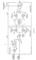
- FIG. 4 A simplified block diagram of an exemplary modulator and transmitter for use in a subscriber station is show in FIG. 4 .
- the traffic channel is interleaved and encoded by the encoder 309 (see FIG. 3 ) before being coupled to the modulator 310.
- the modulator 310 includes a mixer 402 for spreading the traffic channel with a Walsh cover.
- the Walsh covered traffic channel is then provided to a gain element where the relative Walsh gain (F) is applied.
- the relative Walsh gain is generally set by a processor (not shown) to optimize the traffic-pilot ratio for reverse link transmissions.
- the traffic-pilot ratio may be a function of a number of parameters such as the carrier frequency, chip rate, data rate, modulation scheme, frame length, and other parameters.
- the output of the gain element 404 is provided to a summer 406 where it is combined with the pilot channel.
- the combined traffic and pilot channel are then coupled to a mixer 408 where they are spread using the long PN code.
- the spread traffic and pilot channels are then split into a complex signal having an in-phase (I) component and a quadrature phase (Q) component.
- the complex signal is quadrature modulated with the short PN codes by mixers 410a and 410b before being output to the transmitter.
- a complex baseband filter 412 is positioned at the input to the transmitter 312 to reject out of band components of the quadrature modulated signal.
- the filtered complex signal is provided to quadrature mixers 414a and 414b where it is modulated onto a carrier waveform before being combined by a summer 416.
- the combined signal is then provided to a gain element 418 to control the power of the reverse link transmission through the antenna 302 (see FIG. 3 ).
- the gain control signal 314a from the power command generator 314 is used to set the gain of the of the gain element 418.
- the power control loop can be implemented in various ways to maintain a desired quality of service when the traffic channel is silent.
- the velocity of the subscriber station can be used when the traffic channel is silent.
- This approach is well suited for CDMA applications because a closed loop power control scheme can significantly reduce the required energy to achieve a desired quality of service, particularly at low velocities. Since the energy to achieve a desired quality of service varies significantly across various velocities, the set point can be accordingly reduced for some subscriber stations. Since the base station supports a large number of subscriber stations at any given time, statistically these low energy subscriber stations will contribute to bring down the average reverse link transmission power during traffic channel silence, thereby reducing mutual interference among multiple users.
- a number of methods are available for estimating the velocity of the subscriber station.
- a velocity estimation technique base on the characteristics of the pilot channel can be used.
- An envelope level crossing rate LCR can be defined as the average number of positive crossings across a predetermined level (R) per second.
- the pilot signal envelope can be computed by the power estimator 222 in the processor 218.
- the cumulative RPC bits can be used to extract information on the level crossings, excursion times and depths of the pilot signal power for the purpose of constructing the pilot signal envelope.
- the velocity of the subscriber station can be estimated with this technique. It will be understood by those skilled in the art that other velocity estimation techniques may be used without departing from the inventive concepts described throughout.
- the velocity of the subscriber station can be determined through covariance estimation. This technique involves the estimation of auto-covariance between faded samples.
- the velocity of the subscriber station may be estimated through Doppler frequency estimation. The aforementioned techniques are described more fully in U.S. Patent Application No. US 2005/97150 A1 entitled AMethod and Apparatus for Adaptive Power Control in a Wireless Voice and Data Communication System,@ Attorney Docket No. QCPA000268, and assigned to the assignee of the present invention.
- the subscriber station is assigned to one of three velocity groups based on the velocity estimate.
- the three velocity groups include stationary, low speed, and high speed.
- the following exemplary algorithm can be applied over 500 frames with the power control loop generating a RPC bit every 1.25 ms:
- the processor then adjusts the set point as a function of the velocity group to which the subscriber station is assigned when the traffic channel is silent.
- the exact setting for the power set point for each velocity group can be determined empirically by techniques well known in the art. This method may be particularly useful when the subscriber station begins autonomous transmissions without notifying the base station that it is about to begin transmission.
- the power control loop can also be implemented to artificially reduce the power of the reverse link transmission during traffic channel silence.
- this technique is particularly applicable to communications systems in which the traffic between the base station and the subscriber station is scheduled.
- the timing of the reverse link is known, a priori .
- the base station can reduce the power of the pilot channel during periods in which no traffic is scheduled over the reverse link, and ramp up the power of the reverse link transmission prior to the traffic channel becoming active.
- This power reduction technique can be applied independently of the manner in which the scheduling function is implemented.
- an exemplary embodiment of the base station includes a scheduling function implemented by the processor 218.
- the scheduling function can be adapted to control both the forward and reverse link transmissions as a function of the available bandwidth and channel conditions.
- the environmental conditions can be estimated in the processor 218, or other dedicated circuitry, from any number of quality parameters.
- the manner in which the scheduling of transmissions occur depends on whether the transmission is over the forward or reverse link.
- the available bandwidth and estimated channel conditions can be used by the processor 218 to determine when to release traffic from the data queue 210.
- the processor 218 can be configured to monitor an access channel for each subscriber station in its respective area of coverage. When a subscriber station is ready to transmit traffic over the reverse link, it sends a request to all base stations that it is in communication with over its access channel. In response to the request from the subscriber station to transmit traffic, the processor 218 assigns a time slot for that subscriber station based on the number of requests received by the base station and the current channel conditions. The base station transmits the assigned time slot to the requesting subscriber station over the paging channel.
- the set point can be artificially driven to a low level by the set point calculator 220.
- the set point calculator 220 can then artificially increase the set point prior to the time slot assigned to the subscriber station.
- the set point should be increased to the optimal reverse link transmission power early enough to allow the power control loop to drive the reverse link transmission power to the optimal value.
- the set point can be controlled using the FER.
- An alternative power reduction technique involves maintaining the pilot signal power at a low level when the traffic channel is silent, and have the subscriber station autonomously increase its traffic-pilot ratio for a short period of time when the reverse link traffic channel first becomes active.
- This approach can be implemented in communications systems with or without a scheduling function.
- the processor can be adapted to detect when the traffic channel is silent by the absence of decoded frames through methods well known in the art. Once traffic channel silence is detected, the FER estimator 220 can be disabled and the set point can be artificially driven to a low value by the processor 218.
- the relative Walsh gain (F) applied to the gain element 404 in the modulator can be increased.
- the increase in power of the traffic channel should maintain the FER at the desired quality of service while the power control loop ramps up the gain control signal generated by the power command generator 314 (see FIG. 3 ).
- the duration of the increased traffic-pilot ratio can be determined empirically to be substantially equal to the time required for the power control loop to stabilize. Alternatively, the increased traffic-pilot ratio duration can be shortened based on system tradeoffs between the desired quality of service and the short term increase in mutual interference among multiple users.
- the base station should be configured to compensate for any increase in the traffic-pilot ratio.
- the power control loop should be controlled so that it does not stabilize at a set point that is too low to achieve the desired quality of service once the traffic-pilot ratio is reduced. This can be accomplished in any number of ways.
- the set point can be maintained at a fixed value independent of the FER when the traffic-pilot ratio is increased (see FIG. 2 ).
- the traffic-pilot ratio can be reduced to its optimal level, and the power control loop based on the FER can take over.
- the traffic-pilot ratio can be gradually decreased independent of the FER as the set point is ramped up to the optimal value.
- DSP digital signal processor
- ASIC application specific integrated circuit
- FPGA field programmable gate array
- a general purpose processor may be a microprocessor, but in the alternative, the processor may be any conventional processor, controller, microcontroller, or state machine.
- a processor may also be implemented as a combination of computing devices, e.g., a combination of a DSP and a microprocessor, a plurality of microprocessors, one or more microprocessors in conjunction with a DSP core, or any other such configuration.
- a software module may reside in RAM memory, flash memory, ROM memory, EPROM memory, EEPROM memory, registers, hard disk, a removable disk, a CD-ROM, or any other form of storage medium known in the art.
- An exemplary storage medium is coupled to the processor such the processor can read information from, and write information to, the storage medium.
- the storage medium may be integral to the processor.
- the processor and the storage medium may reside in an ASIC.
- the ASIC may reside in a user terminal.
- the processor and the storage medium may reside as discrete components in a user terminal.
Landscapes
- Engineering & Computer Science (AREA)
- Computer Networks & Wireless Communication (AREA)
- Signal Processing (AREA)
- Quality & Reliability (AREA)
- Mobile Radio Communication Systems (AREA)
- Transmitters (AREA)
- Radio Relay Systems (AREA)
- Radio Transmission System (AREA)
- Control Of Eletrric Generators (AREA)
Claims (63)
- Procédé de commande de puissance, comprenant :recevoir une émission comportant un canal ayant une partie active et une partie silencieuse, caractérisé en ce que le procédé comprend en outre l'étape suivante :commander la puissance de l'émission reçue en fonction d'un paramètre de la partie active du canal pendant une première période temporelle dans laquelle le canal est actif, et indépendamment du paramètre pendant une deuxième période temporelle dans laquelle le canal est silencieux.
- Procédé selon la revendication 1, dans lequel le canal comprend un canal de communication.
- Procédé selon la revendication 1, dans lequel le paramètre comprend un taux d'erreur de trame de la partie active du canal.
- Procédé selon la revendication 1, dans lequel la commande de puissance de l'émission reçue comprend en outre l'estimation de la puissance de l'émission reçue, et la commande de la puissance de l'émission reçue en outre en fonction de la puissance estimée.
- Procédé selon la revendication 4, dans lequel l'émission reçue comprend en outre un signal pilote, et l'estimation de puissance comprend l'estimation de la puissance du signal pilote.
- Procédé selon la revendication 4, dans lequel la commande de puissance de l'émission reçue comprend en outre le réglage d'un point de réglage de commande de puissance en fonction du paramètre pendant la première période temporelle, la comparaison du point de réglage de commande de puissance à la puissance estimée, et la commande de la puissance de l'émission reçue en fonction de la comparaison.
- Procédé selon la revendication 6, dans lequel la commande de puissance comprend en outre l'augmentation de la puissance de l'émission reçue si la puissance estimée est inférieure au point de réglage de commande de puissance et la diminution de la puissance de l'émission reçue si la puissance estimée est supérieure au point de réglage de commande de puissance.
- Procédé selon la revendication 6, dans lequel le paramètre comprend un taux d'erreur de trame de la partie active du canal, et le réglage du point de réglage de commande de puissance comprend le réglage du point de réglage de commande de puissance pour obtenir un taux d'erreur fixe prédéterminé pendant la première période temporelle.
- Procédé selon la revendication 6, dans lequel la commande de puissance de l'émission reçue comprend la commande du point de réglage de commande de puissance indépendamment du paramètre pendant la deuxième période temporelle.
- Procédé selon la revendication 9, dans lequel la commande de puissance de l'émission reçue comprend en outre l'estimation d'une vitesse de la source de l'émission reçue, et la commande du point de réglage de commande de puissance en fonction de la vitesse estimée pendant la deuxième période temporelle.
- Procédé selon la revendication 6, dans lequel la commande de puissance de l'émission reçue comprend en outre la détection d'une transition entre la partie active du canal et la partie silencieuse du canal, et la diminution du point de réglage de commande de puissance en fonction de la transition détectée.
- Procédé selon la revendication 6, dans lequel la commande de puissance de l'émission reçue comprend en outre la détection d'une transition entre la partie silencieuse du canal et la partie active du canal, et la terminaison de la deuxième période temporelle après la transition détectée.
- Procédé selon la revendication 6, dans lequel la commande de puissance de l'émission reçue comprend en outre le réglage du point de réglage de commande de puissance à une première puissance au début de la partie silencieuse du canal, et le réglage du point de réglage de commande de puissance à une deuxième puissance supérieure à la première puissance avant la fin de la partie silencieuse du canal.
- Procédé selon la revendication 13, comprenant en outre la programmation de la partie active du canal.
- Procédé selon la revendication 1, dans lequel la première période temporelle correspond à la partie active du canal et la deuxième période temporelle correspond à la partie silencieuse du canal.
- Procédé selon la revendication 15, dans lequel la commande de puissance de l'émission reçue comprend en outre le réglage de la puissance de l'émission reçue à une première puissance au début de la partie silencieuse du canal, et le réglage de la puissance de l'émission reçue à une deuxième puissance supérieure à la première puissance avant la fin de la partie silencieuse du canal.
- Procédé selon la revendication 15, dans lequel la commande de puissance de l'émission reçue comprend en outre l'estimation de la vitesse d'une source de l'émission reçue, et la commande de la puissance de l'émission reçue en fonction de la vitesse estimée pendant la deuxième période temporelle.
- Procédé selon la revendication 1, dans lequel l'émission reçue comprend un deuxième canal, le procédé comprenant en outre le réglage d'un rapport de puissance entre les canaux au début de la partie active du canal et le réglage du rapport de puissance à une valeur différente avant la fin de la partie active du canal.
- Procédé selon la revendication 18, dans lequel le canal comprend un canal de communication et le deuxième canal comprend un canal pilote.
- Procédé selon la revendication 19, dans lequel le réglage du rapport de puissance comprend la réduction de la puissance relative entre le canal de communication et le canal pilote.
- Dispositif agencé pour recevoir une émission comportant un canal ayant une partie active et une partie silencieuse, caractérisé en ce que le dispositif comprend :des moyens d'estimation de paramètre (222) pour estimer un paramètre de la partie active du canal ; etdes moyens de génération de commande de puissance (226, 314) pour produire une commande de puissance en fonction du paramètre estimé pendant une première période temporelle dans laquelle le canal est actif, et indépendamment du paramètre estimé pendant une deuxième période temporelle dans laquelle le canal est silencieux.
- Dispositif selon la revendication 21, dans lequel le canal comprend un canal de communication.
- Dispositif selon la revendication 21, dans lequel le paramètre comprend un taux d'erreur de trame de la partie active du canal.
- Dispositif selon la revendication 21, comprenant en outre des moyens d'estimation de puissance (222) pour estimer la puissance de l'émission reçue, des moyens de point de réglage (220) pour régler un point de réglage de commande de puissance en fonction du paramètre estimé pendant la première période temporelle, et des moyens de comparaison (224) pour comparer la puissance estimée au point de réglage de commande de puissance, la commande de puissance étant fonction de la comparaison.
- Dispositif selon la revendication 24, dans lequel l'émission comprend en outre un signal pilote, et les moyens d'estimation de puissance (222) comprennent des moyens pour estimer la puissance du signal pilote.
- Dispositif selon la revendication 24, dans lequel la commande de puissance comprend une commande d'augmentation de puissance si la puissance estimée est inférieure au point de réglage de commande de puissance et une commande de diminution de puissance si la puissance estimée est supérieure au point de réglage de commande de puissance.
- Dispositif selon la revendication 24, dans lequel le paramètre comprend un taux d'erreur de trame de la partie active du canal, et les moyens de point de réglage comprennent des moyens pour ajuster le point de réglage de commande de puissance pour obtenir un taux d'erreur fixe prédéterminé pendant la première période temporelle.
- Dispositif selon la revendication 24, dans lequel les moyens de réglage (220) comprennent des moyens pour contrôler le point de réglage de commande de puissance indépendamment du paramètre pendant la deuxième période temporelle.
- Dispositif selon la revendication 28, comprenant en outre des moyens d'estimation de vitesse pour estimer la vitesse d'une source de l'émission reçue, et dans lequel les moyens de point de réglage (220) comprennent des moyens pour commander le point de réglage de commande de puissance en fonction de la vitesse estimée pendant la deuxième période temporelle.
- Dispositif selon la revendication 28, comprenant en outre des moyens de détection d'une transition entre la partie active du canal et la partie silencieuse du canal, et dans lequel les moyens de point de réglage comprennent des moyens pour abaisser le point de réglage de commande de puissance en fonction de la transition détectée.
- Dispositif selon la revendication 28, comprenant en outre des moyens de détection d'une transition entre la partie silencieuse du canal et la partie active du canal, la deuxième période temporelle se terminant après la transition détectée entre la partie silencieuse et la partie active.
- Dispositif selon la revendication 28, dans lequel les moyens de point de réglage (220) comprennent des moyens pour ajuster le point de réglage de commande de puissance à une première puissance au début de la partie silencieuse du canal, et pour ajuster le point de réglage de puissance à une deuxième puissance supérieure à la première puissance avant la fin de la partie silencieuse du canal.
- Dispositif selon la revendication 32, comprenant en outre des moyens pour programmer la partie active du canal.
- Dispositif selon la revendication 21, dans lequel les moyens d'estimation de paramètre (222) et les moyens de génération de commande (226) sont constitués d'un processeur configuré (218).
- Dispositif selon la revendication 34, dans lequel le canal comprend un canal de communication.
- Dispositif selon la revendication 34, dans lequel le paramètre comprend un taux d'erreur de trame de la partie active du canal.
- Dispositif selon la revendication 34, dans lequel le processeur (218) est en outre agencé pour estimer la puissance de l'émission reçue, commander un point de réglage de commande de puissance en fonction du paramètre estimé pendant la première période temporelle, et comparer la puissance estimée au point de réglage de commande de puissance, la commande de puissance étant fonction de la comparaison.
- Dispositif selon la revendication 34, dans lequel l'émission comprend en outre un signal pilote, et l'estimation de puissance comprend l'estimation de la puissance du signal pilote.
- Dispositif selon la revendication 37, dans lequel la commande de puissance comprend une commande d'augmentation de puissance si la puissance estimée est inférieure au point de réglage de commande de puissance et une commande de diminution de puissance si la puissance estimée est supérieure au point de réglage de commande de puissance.
- Dispositif selon la revendication 37, dans lequel le paramètre comprend un taux d'erreur de trame de la partie active du canal, et le processeur est en outre agencé pour ajuster le point de réglage de commande de puissance pour obtenir un taux d'erreur fixe prédéterminé pendant la première période temporelle.
- Dispositif selon la revendication 37, dans lequel le processeur (218) est en outre agencé pour commander le point de réglage de commande de puissance indépendamment du paramètre pendant la deuxième période temporelle.
- Dispositif selon la revendication 41, dans lequel le processeur (218) est en outre agencé pour estimer la vitesse d'une source de l'émission reçue, et pour commander le point de réglage de commande de puissance en fonction de la vitesse estimée pendant la deuxième période temporelle.
- Dispositif selon la revendication 41, dans lequel le processeur (218) est en outre agencé pour détecter une transition entre la partie active du canal et la partie silencieuse du canal, et pour abaisser le point de réglage de commande de puissance en fonction de la transition détectée.
- Dispositif selon la revendication 41, dans lequel le processeur (218) est en outre agencé pour détecter une transition entre la partie silencieuse du canal et la partie active du canal, la deuxième période temporelle se terminant après la transition détectée.
- Dispositif selon la revendication 41, dans lequel le processeur (218) est en outre agencé pour régler le point de réglage de commande de puissance à une première puissance au début de la partie silencieuse du canal, et pour régler le point de réglage de commande de puissance à une deuxième puissance supérieure à la première puissance avant la fin de la partie silencieuse du canal.
- Dispositif selon la revendication 45, dans lequel le processeur (218) est en outre agencé pour programmer la partie active du canal.
- Support lisible par ordinateur comprenant des instructions de programme pour faire en sorte qu'un ordinateur réalise un procédé de commande de puissance d'une émission reçue comportant une partie active et une partie silencieuse, caractérisé en ce que le procédé comprend la commande de la puissance de l'émission reçue en fonction d'un paramètre de la partie active du canal pendant une première période temporelle dans laquelle la structure du canal est active, et indépendamment du paramètre pendant une deuxième période temporelle dans laquelle le canal est silencieux.
- Support lisible par ordinateur selon la revendication 47, dans lequel la commande de puissance de l'émission reçue comprend en outre l'estimation de la puissance de l'émission reçue, et la commande de la puissance de l'émission reçue en outre en fonction de la puissance estimée.
- Support lisible par ordinateur selon la revendication 48, dans lequel l'émission reçue comprend en outre un signal pilote, et l'estimation de puissance comprend l'estimation de la puissance du signal pilote.
- Support lisible par ordinateur selon la revendication 48, dans lequel la commande de puissance de l'émission reçue comprend en outre le réglage d'un point de réglage de commande de puissance en fonction du paramètre pendant la première période temporelle, la comparaison du point de réglage de commande de puissance à la puissance estimée, et la commande de la puissance de l'émission reçue en fonction de la comparaison.
- Support lisible par ordinateur selon la revendication 50, dans lequel la commande de puissance comprend en outre l'augmentation de la puissance de l'émission reçue si la puissance estimée est inférieure au point de réglage de commande de puissance et la diminution de la puissance de l'émission reçue si la puissance estimée est supérieure au point de réglage de commande de puissance.
- Support lisible par ordinateur selon la revendication 50, dans lequel le paramètre comprend un taux d'erreur de trame de la partie active du canal, et le réglage du point de réglage de commande de puissance comprend le réglage du point de réglage de commande de puissance pour obtenir un taux d'erreur fixe prédéterminé pendant la première période temporelle.
- Support lisible par ordinateur selon la revendication 50, dans lequel la commande de puissance de la puissance d'émission reçue comprend la commande du point de réglage de commande de puissance indépendamment du paramètre pendant la deuxième période temporelle.
- Support lisible par ordinateur selon la revendication 53, dans lequel la commande de puissance de l'émission reçue comprend en outre l'estimation de la vitesse d'une source de l'émission reçue, et la commande du point de réglage de commande de puissance en fonction de la vitesse estimée pendant la deuxième période temporelle.
- Support lisible par ordinateur selon la revendication 50, dans lequel la commande de puissance de l'émission reçue comprend en outre la détection d'une transition entre la partie active du canal et la partie silencieuse du canal, et la diminution du point de réglage de commande de puissance en fonction de la transition détectée.
- Support lisible par ordinateur selon la revendication 50, dans lequel la commande de puissance de l'émission reçue comprend en outre la détection d'une transition entre la partie silencieuse du canal et la partie active du canal, et la terminaison de la deuxième période temporelle après la transition détectée.
- Support lisible par ordinateur selon la revendication 50, dans lequel la commande de puissance de l'émission reçue comprend en outre le réglage du point de réglage à une première puissance au début de la partie silencieuse du canal, et le réglage du point de réglage de commande de puissance à une deuxième puissance supérieure à la première puissance avant la fin de la partie silencieuse du canal.
- Support lisible par ordinateur selon la revendication 57, dans lequel le procédé comprend en outre la programmation de la partie active du canal.
- Support lisible par ordinateur selon la revendication 47, dans lequel la première période temporelle correspond à la partie active du canal, et la deuxième période temporelle correspond à la partie silencieuse du canal.
- Support lisible par ordinateur selon la revendication 59, dans lequel la commande de puissance de l'émission reçue comprend en outre le réglage de la puissance de l'émission reçue à une première puissance au début de la partie silencieuse du canal, et le réglage de la puissance de l'émission reçue à une deuxième puissance supérieure au premier niveau de puissance avant la fin de la partie silencieuse du canal.
- Support lisible par ordinateur selon la revendication 59, dans lequel la commande de la puissance de l'émission reçue comprend en outre l'estimation de la vitesse d'une source de l'émission reçue, et la commande de la puissance de l'émission reçue en fonction de la vitesse estimée pendant la deuxième période temporelle.
- Support lisible par ordinateur selon la revendication 47, dans lequel l'émission reçue comprend un deuxième canal, le procédé comprenant en outre le réglage d'un rapport de puissance entre les canaux au début de la partie active du canal et le réglage du rapport de puissance à une valeur différente avant la fin de la partie active du canal.
- Support lisible par ordinateur selon la revendication 62, dans lequel le canal comprend un canal de communication et le deuxième canal comprend un canal pilote, et le réglage du rapport de puissance comprend la réduction de la puissance relative entre le canal de communication et le canal pilote.
Priority Applications (2)
| Application Number | Priority Date | Filing Date | Title |
|---|---|---|---|
| EP08152169.2A EP1921772B1 (fr) | 2001-08-29 | 2002-08-22 | Systèmes et techniques de commande de puissance |
| EP10176673.1A EP2254260B1 (fr) | 2001-08-29 | 2002-08-22 | Systèmes et techniques de commande de puissance |
Applications Claiming Priority (3)
| Application Number | Priority Date | Filing Date | Title |
|---|---|---|---|
| US09/942,502 US6842624B2 (en) | 2001-08-29 | 2001-08-29 | Systems and techniques for power control |
| US942502 | 2001-08-29 | ||
| PCT/US2002/027049 WO2003021807A2 (fr) | 2001-08-29 | 2002-08-22 | Systemes et techniques de commande de puissance |
Related Child Applications (2)
| Application Number | Title | Priority Date | Filing Date |
|---|---|---|---|
| EP10176673.1A Division EP2254260B1 (fr) | 2001-08-29 | 2002-08-22 | Systèmes et techniques de commande de puissance |
| EP08152169.2A Division EP1921772B1 (fr) | 2001-08-29 | 2002-08-22 | Systèmes et techniques de commande de puissance |
Publications (2)
| Publication Number | Publication Date |
|---|---|
| EP1421711A2 EP1421711A2 (fr) | 2004-05-26 |
| EP1421711B1 true EP1421711B1 (fr) | 2008-10-22 |
Family
ID=25478163
Family Applications (3)
| Application Number | Title | Priority Date | Filing Date |
|---|---|---|---|
| EP10176673.1A Expired - Lifetime EP2254260B1 (fr) | 2001-08-29 | 2002-08-22 | Systèmes et techniques de commande de puissance |
| EP02761494A Expired - Lifetime EP1421711B1 (fr) | 2001-08-29 | 2002-08-22 | Systemes et techniques de commande de puissance |
| EP08152169.2A Expired - Lifetime EP1921772B1 (fr) | 2001-08-29 | 2002-08-22 | Systèmes et techniques de commande de puissance |
Family Applications Before (1)
| Application Number | Title | Priority Date | Filing Date |
|---|---|---|---|
| EP10176673.1A Expired - Lifetime EP2254260B1 (fr) | 2001-08-29 | 2002-08-22 | Systèmes et techniques de commande de puissance |
Family Applications After (1)
| Application Number | Title | Priority Date | Filing Date |
|---|---|---|---|
| EP08152169.2A Expired - Lifetime EP1921772B1 (fr) | 2001-08-29 | 2002-08-22 | Systèmes et techniques de commande de puissance |
Country Status (11)
| Country | Link |
|---|---|
| US (2) | US6842624B2 (fr) |
| EP (3) | EP2254260B1 (fr) |
| JP (2) | JP4319032B2 (fr) |
| KR (1) | KR100938371B1 (fr) |
| CN (2) | CN1294705C (fr) |
| AT (1) | ATE412278T1 (fr) |
| AU (1) | AU2002326754A1 (fr) |
| DE (1) | DE60229534D1 (fr) |
| HK (1) | HK1070491A1 (fr) |
| TW (1) | TWI223964B (fr) |
| WO (1) | WO2003021807A2 (fr) |
Families Citing this family (38)
| Publication number | Priority date | Publication date | Assignee | Title |
|---|---|---|---|---|
| KR100306286B1 (ko) * | 1998-08-04 | 2001-09-29 | 윤종용 | 부호분할 다중접속 통신시스템의 채널 통신 장치 및 방법 |
| US6728225B1 (en) * | 2000-02-10 | 2004-04-27 | Interdigital Technology Corporation | Asymmetrical forward/reverse transmission bandwidth |
| US7251229B2 (en) * | 2001-08-06 | 2007-07-31 | Qualcomm Incorporated | Systems and techniques for measuring relative power |
| US6842624B2 (en) * | 2001-08-29 | 2005-01-11 | Qualcomm, Incorporated | Systems and techniques for power control |
| CN1156179C (zh) * | 2001-09-03 | 2004-06-30 | 信息产业部电信传输研究所 | 一种信道估计平均区间的动态调整方法和装置 |
| US7840221B1 (en) * | 2001-11-19 | 2010-11-23 | At&T Intellectual Property Ii, L.P. | WLAN having load balancing by beacon power adjustments |
| KR100547852B1 (ko) * | 2002-01-09 | 2006-02-01 | 삼성전자주식회사 | 이동통신 시스템에서 호 수락 방법 |
| US6898193B2 (en) * | 2002-06-20 | 2005-05-24 | Qualcomm, Incorporated | Adaptive gain adjustment control |
| US8504054B2 (en) * | 2002-09-10 | 2013-08-06 | Qualcomm Incorporated | System and method for multilevel scheduling |
| US7630321B2 (en) | 2002-09-10 | 2009-12-08 | Qualcomm Incorporated | System and method for rate assignment |
| US8165148B2 (en) * | 2003-01-13 | 2012-04-24 | Qualcomm Incorporated | System and method for rate assignment |
| US7369876B2 (en) * | 2003-03-04 | 2008-05-06 | Samsung Electronics Co., Ltd. | Apparatus and method for estimating a velocity of a mobile station in a mobile communication system |
| US7746816B2 (en) * | 2003-03-13 | 2010-06-29 | Qualcomm Incorporated | Method and system for a power control in a communication system |
| MXPA05009798A (es) | 2003-03-13 | 2005-12-05 | Qualcomm Inc | Metodo y sistema para transmision de datos en un sistema de comunicacion. |
| US7925291B2 (en) * | 2003-08-13 | 2011-04-12 | Qualcomm Incorporated | User specific downlink power control channel Q-bit |
| KR101009827B1 (ko) * | 2003-09-16 | 2011-01-19 | 삼성전자주식회사 | 이동통신 시스템에서 이동단말의 속도 추정 장치 및 방법 |
| JP4447281B2 (ja) * | 2003-10-20 | 2010-04-07 | 富士通株式会社 | 移動通信システムにおける送信電力制御装置 |
| KR100770842B1 (ko) * | 2003-12-10 | 2007-10-26 | 삼성전자주식회사 | 이동통신 시스템에서 이동국의 역방향 채널 정보 전송장치 및 방법 |
| DE102004014998B4 (de) * | 2004-03-26 | 2006-02-02 | Siemens Ag | Verfahren zum Einstellen der Sendeleistung für eine Funkverbindung, die zwei unterschiedliche Kanäle benutzt, und entsprechende Funkstation |
| KR100842622B1 (ko) * | 2004-06-04 | 2008-06-30 | 삼성전자주식회사 | 통신 시스템에서 속도 추정 장치 및 방법 |
| KR100725773B1 (ko) * | 2004-08-20 | 2007-06-08 | 삼성전자주식회사 | 시분할 듀플렉스 방식의 이동통신 시스템에서 단말기의상태에 따라 상향링크 전력제어방식을 적응적으로변경하기 위한 장치 및 방법 |
| US20060039282A1 (en) * | 2004-08-23 | 2006-02-23 | Lucent Technologies, Inc. | Outer loop power control for high speed data transmissions |
| JP4305341B2 (ja) * | 2004-09-09 | 2009-07-29 | 富士通株式会社 | 無線通信装置、無線基地局、無線基地局制御装置、送信電力制御方法 |
| GB0420847D0 (en) * | 2004-09-20 | 2004-10-20 | Koninkl Philips Electronics Nv | A radio communication system, a radio station, and a method of transmitting data |
| JP2006311490A (ja) * | 2005-03-30 | 2006-11-09 | Hitachi Kokusai Electric Inc | 無線基地局装置 |
| JP4713919B2 (ja) * | 2005-04-14 | 2011-06-29 | 株式会社エヌ・ティ・ティ・ドコモ | 無線通信制御システム、無線基地局及び無線通信制御方法 |
| US20060245370A1 (en) * | 2005-04-27 | 2006-11-02 | Murali Ranganathan | Method of quality of service reduction |
| WO2006118301A1 (fr) * | 2005-05-02 | 2006-11-09 | Ntt Docomo, Inc. | Procede de controle de la puissance de transmission, station mobile, station de base de radio et station de commande de reseau radio |
| US20070036121A1 (en) * | 2005-08-12 | 2007-02-15 | George Cherian | Method and apparatus for providing reverse activity information in a multi-carrier communication system |
| KR20070073059A (ko) * | 2006-01-03 | 2007-07-10 | 삼성전자주식회사 | 이동통신 시스템의 전력 제어 장치 및 방법 |
| US8260340B2 (en) * | 2006-02-17 | 2012-09-04 | Alcatel Lucent | Methods of reverse link power control |
| DE102008043215A1 (de) * | 2008-10-28 | 2010-04-29 | Robert Bosch Gmbh | Werkzeugmaschinenschutzvorrichtung |
| US8913563B2 (en) * | 2009-02-06 | 2014-12-16 | Empire Technology Development Llc | Velocity based random access scheme |
| JP5423505B2 (ja) * | 2010-03-17 | 2014-02-19 | 富士通株式会社 | 無線基地局及び通信方法 |
| GB2489757B (en) * | 2011-05-16 | 2013-12-18 | Renesas Mobile Corp | Mobile Communications Network |
| CN102196542B (zh) * | 2011-05-27 | 2014-06-25 | 上海华为技术有限公司 | 功率控制方法、设备和系统 |
| CN104661295B (zh) * | 2015-01-24 | 2018-01-16 | 杭州敦崇科技股份有限公司 | 基于速率集的逐包功率控制方法 |
| CN112512108B (zh) * | 2020-12-02 | 2022-09-02 | 中国联合网络通信集团有限公司 | 功率控制方法及通信装置 |
Family Cites Families (12)
| Publication number | Priority date | Publication date | Assignee | Title |
|---|---|---|---|---|
| CN1124712C (zh) | 1997-10-14 | 2003-10-15 | 夸尔柯姆股份有限公司 | 通信系统中测量非线性影响并根据结果选择信道的方法和装置 |
| JP3119605B2 (ja) * | 1997-10-28 | 2000-12-25 | 埼玉日本電気株式会社 | 無線基地局 |
| FI105131B (fi) | 1998-03-27 | 2000-06-15 | Nokia Networks Oy | Menetelmä fyysisen kanavan tehonsäädön suorittamiseksi radiojärjestelmässä |
| KR20000014423A (ko) * | 1998-08-17 | 2000-03-15 | 윤종용 | 부호분할다중접속 통신시스템의 통신제어장치 및 방법 |
| KR100433910B1 (ko) * | 1999-02-13 | 2004-06-04 | 삼성전자주식회사 | 부호분할다중접속 통신시스템의 주파수간핸드오프를 위한 전력 |
| EP1039657A1 (fr) * | 1999-03-19 | 2000-09-27 | Alcatel | Procédé de contrôle de la puissance de transmission d'un signal pilote dans un système de radiocommunication mobile AMCR, et une station de base et une station mobile pour un tel système |
| JP2000278207A (ja) * | 1999-03-23 | 2000-10-06 | Oki Electric Ind Co Ltd | 送信電力制御方法及び無線通信装置 |
| WO2001001599A1 (fr) * | 1999-06-23 | 2001-01-04 | Siemens Aktiengesellschaft | Procede de reglage de la puissance d'emission dans un systeme radio, et systeme radio correspondant |
| ES2314329T3 (es) | 1999-07-13 | 2009-03-16 | Alcatel Lucent | Metodo para mejorar la caracterisiticas de funcionamiento de un sistema movil de radiocomunicacion que utiliza un algoritmo de control de potencia. |
| US6587447B1 (en) | 1999-09-29 | 2003-07-01 | Nortel Networks Limited | Method and system for performing outer loop power control in discontinuous transmission mode |
| US6590874B1 (en) * | 1999-09-30 | 2003-07-08 | Nortel Networks Limited | Method and system for implementing outer loop power control in discontinuous transmission mode using explicit signalling |
| US6842624B2 (en) * | 2001-08-29 | 2005-01-11 | Qualcomm, Incorporated | Systems and techniques for power control |
-
2001
- 2001-08-29 US US09/942,502 patent/US6842624B2/en not_active Expired - Lifetime
-
2002
- 2002-08-22 CN CNB028212088A patent/CN1294705C/zh not_active Expired - Lifetime
- 2002-08-22 AT AT02761494T patent/ATE412278T1/de not_active IP Right Cessation
- 2002-08-22 JP JP2003526020A patent/JP4319032B2/ja not_active Expired - Lifetime
- 2002-08-22 WO PCT/US2002/027049 patent/WO2003021807A2/fr active Application Filing
- 2002-08-22 EP EP10176673.1A patent/EP2254260B1/fr not_active Expired - Lifetime
- 2002-08-22 EP EP02761494A patent/EP1421711B1/fr not_active Expired - Lifetime
- 2002-08-22 KR KR1020047003044A patent/KR100938371B1/ko active IP Right Grant
- 2002-08-22 AU AU2002326754A patent/AU2002326754A1/en not_active Abandoned
- 2002-08-22 CN CN200610163961XA patent/CN1964214B/zh not_active Expired - Lifetime
- 2002-08-22 EP EP08152169.2A patent/EP1921772B1/fr not_active Expired - Lifetime
- 2002-08-22 DE DE60229534T patent/DE60229534D1/de not_active Expired - Lifetime
- 2002-08-29 TW TW091119681A patent/TWI223964B/zh not_active IP Right Cessation
-
2004
- 2004-10-15 US US10/966,130 patent/US20050048937A1/en not_active Abandoned
-
2005
- 2005-04-08 HK HK05102989A patent/HK1070491A1/xx not_active IP Right Cessation
-
2009
- 2009-01-08 JP JP2009002710A patent/JP4885986B2/ja not_active Expired - Lifetime
Also Published As
| Publication number | Publication date |
|---|---|
| JP2005502262A (ja) | 2005-01-20 |
| KR20040029120A (ko) | 2004-04-03 |
| JP2009153147A (ja) | 2009-07-09 |
| US6842624B2 (en) | 2005-01-11 |
| EP1921772B1 (fr) | 2016-02-24 |
| EP2254260A3 (fr) | 2017-04-12 |
| HK1070491A1 (en) | 2005-06-17 |
| DE60229534D1 (de) | 2008-12-04 |
| EP1421711A2 (fr) | 2004-05-26 |
| KR100938371B1 (ko) | 2010-01-22 |
| EP2254260A2 (fr) | 2010-11-24 |
| EP1921772A2 (fr) | 2008-05-14 |
| CN1964214B (zh) | 2010-05-26 |
| US20050048937A1 (en) | 2005-03-03 |
| US20030045319A1 (en) | 2003-03-06 |
| CN1294705C (zh) | 2007-01-10 |
| JP4885986B2 (ja) | 2012-02-29 |
| EP1921772A3 (fr) | 2011-08-10 |
| ATE412278T1 (de) | 2008-11-15 |
| CN1964214A (zh) | 2007-05-16 |
| TWI223964B (en) | 2004-11-11 |
| WO2003021807A3 (fr) | 2003-11-06 |
| EP2254260B1 (fr) | 2019-05-15 |
| JP4319032B2 (ja) | 2009-08-26 |
| WO2003021807A2 (fr) | 2003-03-13 |
| CN1575554A (zh) | 2005-02-02 |
| AU2002326754A1 (en) | 2003-03-18 |
Similar Documents
| Publication | Publication Date | Title |
|---|---|---|
| EP1421711B1 (fr) | Systemes et techniques de commande de puissance | |
| EP1584166B1 (fr) | Ordonnanceur a priorite a durees de programmation variables et a durees programmees variables | |
| US7069035B2 (en) | Method and apparatus for power control in a communication system | |
| US7010321B2 (en) | Power control avoiding outer loop wind-up | |
| US7734262B2 (en) | Method and apparatus for reverse link throttling in a multi-carrier wireless communication system | |
| EP1908184B1 (fr) | Commande de puissance de transmission de liaison retour dans un système de communication sans fil | |
| EP2031763A2 (fr) | Système et procédé d'affectation de débit | |
| AU2002312547B2 (en) | Method and apparatus for controlling gain level of a supplemental channel in a CDMA communication system | |
| US7363010B2 (en) | Power control for intermittently active data channels in a wireless communication system | |
| EP1391134B1 (fr) | Procédé et appareil permettant de commender les demandes d'appel dans un système de communication | |
| KR100798185B1 (ko) | 무선 통신 시스템에서 다수의 전송 채널들에 대한 전력제어 | |
| EP1415412B1 (fr) | Procede et appareil destines a commander le niveau de gain d'un canal de communication dans un systeme de communication a acces multiple par repartition en code |
Legal Events
| Date | Code | Title | Description |
|---|---|---|---|
| PUAI | Public reference made under article 153(3) epc to a published international application that has entered the european phase |
Free format text: ORIGINAL CODE: 0009012 |
|
| 17P | Request for examination filed |
Effective date: 20040317 |
|
| AK | Designated contracting states |
Kind code of ref document: A2 Designated state(s): AT BE BG CH CY CZ DE DK EE ES FI FR GB GR IE IT LI LU MC NL PT SE SK TR |
|
| AX | Request for extension of the european patent |
Extension state: AL LT LV MK RO SI |
|
| 17Q | First examination report despatched |
Effective date: 20070209 |
|
| GRAP | Despatch of communication of intention to grant a patent |
Free format text: ORIGINAL CODE: EPIDOSNIGR1 |
|
| GRAS | Grant fee paid |
Free format text: ORIGINAL CODE: EPIDOSNIGR3 |
|
| GRAA | (expected) grant |
Free format text: ORIGINAL CODE: 0009210 |
|
| AK | Designated contracting states |
Kind code of ref document: B1 Designated state(s): AT BE BG CH CY CZ DE DK EE ES FI FR GB GR IE IT LI LU MC NL PT SE SK TR |
|
| REG | Reference to a national code |
Ref country code: GB Ref legal event code: FG4D |
|
| REG | Reference to a national code |
Ref country code: CH Ref legal event code: EP |
|
| REG | Reference to a national code |
Ref country code: IE Ref legal event code: FG4D |
|
| REF | Corresponds to: |
Ref document number: 60229534 Country of ref document: DE Date of ref document: 20081204 Kind code of ref document: P |
|
| NLV1 | Nl: lapsed or annulled due to failure to fulfill the requirements of art. 29p and 29m of the patents act | ||
| PG25 | Lapsed in a contracting state [announced via postgrant information from national office to epo] |
Ref country code: ES Free format text: LAPSE BECAUSE OF FAILURE TO SUBMIT A TRANSLATION OF THE DESCRIPTION OR TO PAY THE FEE WITHIN THE PRESCRIBED TIME-LIMIT Effective date: 20090202 Ref country code: BG Free format text: LAPSE BECAUSE OF FAILURE TO SUBMIT A TRANSLATION OF THE DESCRIPTION OR TO PAY THE FEE WITHIN THE PRESCRIBED TIME-LIMIT Effective date: 20090122 Ref country code: AT Free format text: LAPSE BECAUSE OF FAILURE TO SUBMIT A TRANSLATION OF THE DESCRIPTION OR TO PAY THE FEE WITHIN THE PRESCRIBED TIME-LIMIT Effective date: 20081022 |
|
| PG25 | Lapsed in a contracting state [announced via postgrant information from national office to epo] |
Ref country code: FI Free format text: LAPSE BECAUSE OF FAILURE TO SUBMIT A TRANSLATION OF THE DESCRIPTION OR TO PAY THE FEE WITHIN THE PRESCRIBED TIME-LIMIT Effective date: 20081022 Ref country code: NL Free format text: LAPSE BECAUSE OF FAILURE TO SUBMIT A TRANSLATION OF THE DESCRIPTION OR TO PAY THE FEE WITHIN THE PRESCRIBED TIME-LIMIT Effective date: 20081022 Ref country code: PT Free format text: LAPSE BECAUSE OF FAILURE TO SUBMIT A TRANSLATION OF THE DESCRIPTION OR TO PAY THE FEE WITHIN THE PRESCRIBED TIME-LIMIT Effective date: 20090323 |
|
| PG25 | Lapsed in a contracting state [announced via postgrant information from national office to epo] |
Ref country code: BE Free format text: LAPSE BECAUSE OF FAILURE TO SUBMIT A TRANSLATION OF THE DESCRIPTION OR TO PAY THE FEE WITHIN THE PRESCRIBED TIME-LIMIT Effective date: 20081022 Ref country code: DK Free format text: LAPSE BECAUSE OF FAILURE TO SUBMIT A TRANSLATION OF THE DESCRIPTION OR TO PAY THE FEE WITHIN THE PRESCRIBED TIME-LIMIT Effective date: 20081022 Ref country code: EE Free format text: LAPSE BECAUSE OF FAILURE TO SUBMIT A TRANSLATION OF THE DESCRIPTION OR TO PAY THE FEE WITHIN THE PRESCRIBED TIME-LIMIT Effective date: 20081022 |
|
| PLBE | No opposition filed within time limit |
Free format text: ORIGINAL CODE: 0009261 |
|
| STAA | Information on the status of an ep patent application or granted ep patent |
Free format text: STATUS: NO OPPOSITION FILED WITHIN TIME LIMIT |
|
| PG25 | Lapsed in a contracting state [announced via postgrant information from national office to epo] |
Ref country code: CZ Free format text: LAPSE BECAUSE OF FAILURE TO SUBMIT A TRANSLATION OF THE DESCRIPTION OR TO PAY THE FEE WITHIN THE PRESCRIBED TIME-LIMIT Effective date: 20081022 Ref country code: IT Free format text: LAPSE BECAUSE OF FAILURE TO SUBMIT A TRANSLATION OF THE DESCRIPTION OR TO PAY THE FEE WITHIN THE PRESCRIBED TIME-LIMIT Effective date: 20081022 Ref country code: SE Free format text: LAPSE BECAUSE OF FAILURE TO SUBMIT A TRANSLATION OF THE DESCRIPTION OR TO PAY THE FEE WITHIN THE PRESCRIBED TIME-LIMIT Effective date: 20090122 |
|
| 26N | No opposition filed |
Effective date: 20090723 |
|
| PG25 | Lapsed in a contracting state [announced via postgrant information from national office to epo] |
Ref country code: SK Free format text: LAPSE BECAUSE OF FAILURE TO SUBMIT A TRANSLATION OF THE DESCRIPTION OR TO PAY THE FEE WITHIN THE PRESCRIBED TIME-LIMIT Effective date: 20081022 |
|
| PG25 | Lapsed in a contracting state [announced via postgrant information from national office to epo] |
Ref country code: MC Free format text: LAPSE BECAUSE OF NON-PAYMENT OF DUE FEES Effective date: 20090831 |
|
| REG | Reference to a national code |
Ref country code: CH Ref legal event code: PL |
|
| PG25 | Lapsed in a contracting state [announced via postgrant information from national office to epo] |
Ref country code: LI Free format text: LAPSE BECAUSE OF NON-PAYMENT OF DUE FEES Effective date: 20090831 Ref country code: CH Free format text: LAPSE BECAUSE OF NON-PAYMENT OF DUE FEES Effective date: 20090831 |
|
| PG25 | Lapsed in a contracting state [announced via postgrant information from national office to epo] |
Ref country code: IE Free format text: LAPSE BECAUSE OF NON-PAYMENT OF DUE FEES Effective date: 20090822 |
|
| PG25 | Lapsed in a contracting state [announced via postgrant information from national office to epo] |
Ref country code: GR Free format text: LAPSE BECAUSE OF FAILURE TO SUBMIT A TRANSLATION OF THE DESCRIPTION OR TO PAY THE FEE WITHIN THE PRESCRIBED TIME-LIMIT Effective date: 20090123 |
|
| PG25 | Lapsed in a contracting state [announced via postgrant information from national office to epo] |
Ref country code: LU Free format text: LAPSE BECAUSE OF NON-PAYMENT OF DUE FEES Effective date: 20090822 |
|
| PG25 | Lapsed in a contracting state [announced via postgrant information from national office to epo] |
Ref country code: TR Free format text: LAPSE BECAUSE OF FAILURE TO SUBMIT A TRANSLATION OF THE DESCRIPTION OR TO PAY THE FEE WITHIN THE PRESCRIBED TIME-LIMIT Effective date: 20081022 |
|
| PG25 | Lapsed in a contracting state [announced via postgrant information from national office to epo] |
Ref country code: CY Free format text: LAPSE BECAUSE OF FAILURE TO SUBMIT A TRANSLATION OF THE DESCRIPTION OR TO PAY THE FEE WITHIN THE PRESCRIBED TIME-LIMIT Effective date: 20081022 |
|
| REG | Reference to a national code |
Ref country code: FR Ref legal event code: PLFP Year of fee payment: 15 |
|
| REG | Reference to a national code |
Ref country code: FR Ref legal event code: PLFP Year of fee payment: 16 |
|
| REG | Reference to a national code |
Ref country code: FR Ref legal event code: PLFP Year of fee payment: 17 |
|
| PGFP | Annual fee paid to national office [announced via postgrant information from national office to epo] |
Ref country code: NL Payment date: 20180712 Year of fee payment: 17 |
|
| PG25 | Lapsed in a contracting state [announced via postgrant information from national office to epo] |
Ref country code: FR Free format text: LAPSE BECAUSE OF NON-PAYMENT OF DUE FEES Effective date: 20190831 |
|
| PGFP | Annual fee paid to national office [announced via postgrant information from national office to epo] |
Ref country code: GB Payment date: 20210728 Year of fee payment: 20 Ref country code: DE Payment date: 20210713 Year of fee payment: 20 |
|
| REG | Reference to a national code |
Ref country code: DE Ref legal event code: R071 Ref document number: 60229534 Country of ref document: DE |
|
| REG | Reference to a national code |
Ref country code: GB Ref legal event code: PE20 Expiry date: 20220821 |
|
| PG25 | Lapsed in a contracting state [announced via postgrant information from national office to epo] |
Ref country code: GB Free format text: LAPSE BECAUSE OF EXPIRATION OF PROTECTION Effective date: 20220821 |