EP1420930B1 - Procede et dispositif de production automatique de plaques minces - Google Patents
Procede et dispositif de production automatique de plaques minces Download PDFInfo
- Publication number
- EP1420930B1 EP1420930B1 EP02747131A EP02747131A EP1420930B1 EP 1420930 B1 EP1420930 B1 EP 1420930B1 EP 02747131 A EP02747131 A EP 02747131A EP 02747131 A EP02747131 A EP 02747131A EP 1420930 B1 EP1420930 B1 EP 1420930B1
- Authority
- EP
- European Patent Office
- Prior art keywords
- mould
- injection
- phase
- sprue
- nozzle
- Prior art date
- Legal status (The legal status is an assumption and is not a legal conclusion. Google has not performed a legal analysis and makes no representation as to the accuracy of the status listed.)
- Expired - Lifetime
Links
Images


Classifications
-
- B—PERFORMING OPERATIONS; TRANSPORTING
- B29—WORKING OF PLASTICS; WORKING OF SUBSTANCES IN A PLASTIC STATE IN GENERAL
- B29C—SHAPING OR JOINING OF PLASTICS; SHAPING OF MATERIAL IN A PLASTIC STATE, NOT OTHERWISE PROVIDED FOR; AFTER-TREATMENT OF THE SHAPED PRODUCTS, e.g. REPAIRING
- B29C45/00—Injection moulding, i.e. forcing the required volume of moulding material through a nozzle into a closed mould; Apparatus therefor
- B29C45/17—Component parts, details or accessories; Auxiliary operations
- B29C45/38—Cutting-off equipment for sprues or ingates
-
- B—PERFORMING OPERATIONS; TRANSPORTING
- B29—WORKING OF PLASTICS; WORKING OF SUBSTANCES IN A PLASTIC STATE IN GENERAL
- B29C—SHAPING OR JOINING OF PLASTICS; SHAPING OF MATERIAL IN A PLASTIC STATE, NOT OTHERWISE PROVIDED FOR; AFTER-TREATMENT OF THE SHAPED PRODUCTS, e.g. REPAIRING
- B29C45/00—Injection moulding, i.e. forcing the required volume of moulding material through a nozzle into a closed mould; Apparatus therefor
- B29C45/17—Component parts, details or accessories; Auxiliary operations
- B29C45/46—Means for plasticising or homogenising the moulding material or forcing it into the mould
- B29C45/56—Means for plasticising or homogenising the moulding material or forcing it into the mould using mould parts movable during or after injection, e.g. injection-compression moulding
- B29C45/561—Injection-compression moulding
-
- B—PERFORMING OPERATIONS; TRANSPORTING
- B29—WORKING OF PLASTICS; WORKING OF SUBSTANCES IN A PLASTIC STATE IN GENERAL
- B29C—SHAPING OR JOINING OF PLASTICS; SHAPING OF MATERIAL IN A PLASTIC STATE, NOT OTHERWISE PROVIDED FOR; AFTER-TREATMENT OF THE SHAPED PRODUCTS, e.g. REPAIRING
- B29C45/00—Injection moulding, i.e. forcing the required volume of moulding material through a nozzle into a closed mould; Apparatus therefor
- B29C45/17—Component parts, details or accessories; Auxiliary operations
- B29C45/38—Cutting-off equipment for sprues or ingates
- B29C2045/384—Cutting-off equipment for sprues or ingates cutting the sprue by a plunger movable into the runner channel
- B29C2045/386—Cutting-off equipment for sprues or ingates cutting the sprue by a plunger movable into the runner channel returning the cutted sprue into the injection nozzle
-
- B—PERFORMING OPERATIONS; TRANSPORTING
- B29—WORKING OF PLASTICS; WORKING OF SUBSTANCES IN A PLASTIC STATE IN GENERAL
- B29C—SHAPING OR JOINING OF PLASTICS; SHAPING OF MATERIAL IN A PLASTIC STATE, NOT OTHERWISE PROVIDED FOR; AFTER-TREATMENT OF THE SHAPED PRODUCTS, e.g. REPAIRING
- B29C45/00—Injection moulding, i.e. forcing the required volume of moulding material through a nozzle into a closed mould; Apparatus therefor
- B29C45/17—Component parts, details or accessories; Auxiliary operations
- B29C45/20—Injection nozzles
- B29C45/23—Feed stopping equipment
-
- B—PERFORMING OPERATIONS; TRANSPORTING
- B29—WORKING OF PLASTICS; WORKING OF SUBSTANCES IN A PLASTIC STATE IN GENERAL
- B29L—INDEXING SCHEME ASSOCIATED WITH SUBCLASS B29C, RELATING TO PARTICULAR ARTICLES
- B29L2017/00—Carriers for sound or information
- B29L2017/001—Carriers of records containing fine grooves or impressions, e.g. disc records for needle playback, cylinder records
- B29L2017/003—Records or discs
- B29L2017/005—CD''s, DVD''s
Definitions
- the invention relates to a method for the automatic production of thin plates, in particular of optical data media or CD's, with a central opening, according to the preamble of claim 1.
- the invention relates also a device according to the preamble of claim 7.
- Conventional injection molding machines usually have two mold halves.
- the one movable, first half of the mold is compared by means of a drive system fixed drive carrier plate for the mold closing and the mold opening moves.
- the two mold halves are at the beginning of each casting cycle with such a Great closing force compressed that even among the highest Melting pressures can come to no opening of the molds.
- Typically at classical injection molding is a prolonged postpress period after completion the complete mold filling. The pressure is transferred through the injection screw maintain the sprue in the sense of a hydraulic pressure.
- the final shape of the injection molded body is only by colliding the two Mold halves during the embossing phase after initially only partial mold cavity filling reached.
- the embossing phase is a key phase here.
- the driven one Mold half is used for making flat media prior to injection drove a predetermined position and about for the period of injection in held the position of a Complexgespaltes. Thereafter, using the compression pressure the corresponding board or the driven first mold half closer to the second Schmidtformhhan encountered with simultaneous application of the Embossing pressure.
- the embossing gap is canceled up to a small distance. It will a fully effective reprint by applying a compression pressure produced directly over the mold halves, for which a driven mold half against the Gegenformhget is moved.
- reprint is the surface Force understood by the one half of the mold.
- the reprint is the Corresponding replacement for that by the injection screw movement in the classical Injection molding applied "hydraulic" reprints by means of pressure transmission of liquid melt through the injection nozzle.
- a very special feature of flat data carriers is the central opening.
- the central opening is used when holding the disk as a holder and the Centering.
- the inner opening must therefore with the highest accuracy and the inner edge are produced with the highest surface quality.
- a "soft-cut” When “soft-cut” the middle opening is produced in the still liquid mass.
- the "hard-cut” is only made when the product is already largely solidified.
- the CH-PS 453 671 suggests a "hard-cut” just before the spray mass completely solidified, before.
- each of the two molds is one perpendicular to each the flat body movable stamp. These two stamps produce with one coordinated penetration by the flat body first on the one and then on the other side the middle opening. The rest remains with each cut Sprue, which is related to the circular "punching disc”.
- EP-A-0 051 252 proposes an actual poppet valve which is on the side of the Spray nozzle is arranged and depending on the position of the melt supply only during the injection phase releases and prevents them during the rest of the time.
- the proposed valve assembly with the thereby used for use "soft-cut" no Angussteil generated.
- the disadvantage is the much larger design effort for driving the moving parts on the Side of the spray nozzle.
- U.S. Patent No. 4,466,934 proposes both the "hard” and the like the “soft-cut” before.
- the "hard-cut” is made by a tubular cutting punch made, which at least partially solidified mass by means of a corresponding cutting movement in the direction of the die on the opposite side or Pierces injection side.
- the punched disc for the central opening is located within the tubular cutting punch and is passed through a guide tube with an undercut in a central bore held in solidified state.
- the mouth piece is formed narrowed the injection nozzle, which fluidly for the Injection is rather disadvantageous.
- JP-A-02 198 816 discloses a method for automatically producing Plates having a central opening, wherein the two mold halves each for a Start position of an injection cycle positioned for the injection phase. A dosed Amount of resin is injected. The breakthrough for the middle opening is by a Movement of a stamp after completion of the injection phase, during the Cooling phase, however, before complete solidification of the sprue area, by Reduction of the sprue volume generated. The casting will be up to a sufficient Removal resistance cooled and the finished plate and the sprue with Middle opening part taken from the mold halves. The timing for the Production of the opening for the middle opening and the beginning of the dosing is left open. Also according to EP-A-0 620 097 the timing for the Production of the opening for the middle opening and the beginning of the dosing left open.
- EP 0 640 460 proposes to start the tool-opening operation as the injection proceeds, and to monitor the pressure within the cavity by means of a pressure sensor as the injection step proceeds and to interrupt the injection of the resin when a predetermined pressure has been reached is to allow the backflow of molten resin from the cavity during the closing step.
- the predetermined pressure may be between 200 and 300 kg / cm 2 with a desired thickness of the molded part of less than 1 mm.
- the pressure sensor is installed at 70 to 80% of the flow distance of the molded product.
- the compensating flow described has a direct influence on the final weight of the part to be formed, because the "soft-cut" interrupts the connection between the screw antechamber and the cavity for the finished data carrier.
- a data carrier depending on whether a "soft-cut” or a “hard-cut” is made, for example, according to US-PS 4,466,934, may have a different final weight.
- the invention has now been based on the object, a method and a To develop apparatus for the production of thin plates with central opening, which an optimization of a whole injection molding process and in the increase the weight accuracy of the finished injection molded parts also optimize the Quality of the entire data carrier by using an open nozzle and a Simplification of the tool design allowed.
- the inventive method is characterized in that the breakthrough for the middle opening after completion of the post-pressure phase or the embossing phase, by backflow into the Schneckenvorraum is generated and the dosing phase for each subsequent Injection cycle with the completion of the movement of the punch for the breakthrough of Middle opening begins, the remindströmmasse from the reduction of Runner volume for the dosing amount is also included.
- the device according to the invention is characterized in that the control means are designed to carry out the stamp movement, time after completion the post-pressure phase or the embossing phase, wherein the control means are designed such that the dosing for the subsequent injection cycle with the completion of the movement of the Stamp for the opening of the center opening begins, and the remindströmmasse from the reduction of the sprue volume for the dosing amount is taken into account.
- the production of the druchbruches can be temporal and / or as a function of Melt temperature and / or controlled as a function of the pressure in the mold become.
- the new solution thus allows, as it were passively, the "cut" during the the best possible time period of a whole Spritzzyklusses or with regard to to optimize the other parameters.
- every control just because of a temporally optimized process the easiest and cheapest.
- the breakthrough for the Middle opening is only after completion of the emphasis phase or after completion of the embossing phase during the cooling phase by a stamp, which on a female opening on the side of the spray nozzle and wegbewegbar is generated.
- the Stamp inside have an undercut and an ejector. By the Undercut remains the sprue after sufficient solidification in the stamp front part held. When the mold is open, the sprue is activated by pressing the ejector discarded.
- the spray nozzle will always remain open during normal production and the nozzle preferably pressed against the injection mold.
- the injection nozzle is closed educated. At least the first dosage when starting for a new Production can be done with the nozzle closed and the subsequent production cycles be carried out at permanently open nozzle. In injection molding practice it is announced that the first plate produced by a new production series is useless. It is not possible in the prior art, the dosage for the prepare each first shot with sufficient accuracy.
- the disadvantage is that the results of the first record only bad as the basis for the correction of a second plate can be used. With the new solution must be for the first Plate of a new series only the geometrical data between lock and Nozzle tip be known, so this when dosing for the first shot can be considered.
- the product of the first shot is in accordance with new solution theoretically useful, but can at least for one Fine adjustment can be used for the second shot.
- the stamp forms with withdrawn ejector pin with an undercut in the stamp a holding space for the sprue, in which this sufficient after Solidification and after open form by pressing the ejector pin is again ejected.
- the stamp may be one-piece or two-piece, such as according to US-PS 4,466,934, be formed.
- the one-piece stamp has advantages insofar as this one big Life has opposite a tubular stamped part with razor sharp circular edge.
- the device has a fixed Mold half and a movable mold half, wherein the stamp with Ejector pin on the side of the movable mold half and the injector on the side of the fixed mold half is arranged.
- the nozzle closure as a needle, rotary valve or Form plug closure.
- the new solution is the type and frequency the operation of the nozzle closure is not limited in principle. Prefers However, only one operation at the beginning of a new production series. For that can the structural design are relatively simple and robust. The question of Service life is almost non-existent.
- the closure can be used as a controlled start valve be formed, such that when you first start for a new Production series closed the closure during the first dosing, for the subsequent normal production cycles permanently open and the nozzle preferably always pressed pressed on the tool.
- the closure body preferably has a free passage in the open state flow cross section without flow flow between the antechamber and the cavity the injection mold on.
- FIG. 1 shows a known solution of the prior art. With the machine a CD is made in 3.7 seconds or less. It is about a Solution of the Applicant. Shown is a fully hydraulic machine 10 with a lot good machine stability characteristics and has three pillars as well the possibility for a short and a Lahghub on.
- the short-stroke is 70 to 80 mm, and the closing force is about 600 kN.
- the maintenance stroke is about totally 300 mm.
- a mold plate 1 is fixedly connected to a machine stand 8.
- the tie rods 2 are screwed to the mold plate 1, wherein at the other end of the Tie rods 2, a piston head 3 is located within a cylinder 4.
- the Mold plate 5 is drawn in a production position, wherein the piston head.
- the machine 10 is open Protective door 6, with a view of the positive connection and the injection cylinder 7, shown.
- the raw material is fed via filling container 9 of the machine, via the Injection cylinder heated and injected under pressure into the cavities of the molds.
- Figures 1 and 2 show the basic concept for the production of flat Data carriers, such as compact disks.
- a cavity In the center of the machine is a cavity, which ultimately determines the outer shape of the data carrier.
- various concepts have been pursued.
- a quantity of the spray mass is metered into the cavity, so that a part of the cavity is filled.
- a predetermined compression gap Prior to the filling is done by moving formed the mold plate 1 or the mold plate 5, a predetermined compression gap.
- the movable mold plate is in Direction of the cavity moves and applying a maximum force of the mold cavity or the cavity is reduced and the mass compacted.
- the compression gap is canceled to 0.
- the tools are no longer driven to the stop. It is rather a residual gap for an exact final control, even after completion of the embossing.
- FIG. 2 shows an example of the new solution with toothed belts driven Columns 30.
- the nozzle side Tool clamping plate or Langhubarmeplatte 11 with a movable Mold half 12 shown on the back, according to arrows 13, the injection nozzle 7 and can be moved away.
- the Langhubarmeplatte 11 may, depending on the selected Concept, fixed or movable on the machine stand 8 are arranged.
- On The right side of the image is a compact solution as a preferred solution Assembly 14 with a crank drive.
- the assembly 14 consists of a Drive carrier plate 15 and a movable platen 16, the on a guide 20 rests on the machine bed 8, and a Crank carrier construction 17.
- a crank mechanism 18 is on the one hand via a pin 19 in the movable platen 16 and on the other hand via an eccentric 21st articulated in the crank support structure 17 such that the crank 22, according to the eccentricity e, which can perform crank movement.
- the Eccentricity e corresponds to half the lifting height (H / 2).
- the movable mold clamping plate 16 is the one movable Form half 23. With the two mold halves 12 and 23 is formed in a closed Condition of the cavity or the cavity 24 for the deposit of the desired disc-shaped molding. Usually, the CD is not directly in the cavity 24 poured. In the cavity is one or both sides each stamper 25, 26th inserted, which as a negative mold, the cavity for the flat to be produced Have disk.
- Each column 30 is anchored on the nozzle-side platen 11 via a nut 31.
- a rotatable collar 32 attached, which via a ring gear 33 engages in a toothed tire 34.
- the fixed nut 31 engages over an internal thread on the threaded hole 35 of each column 30 a.
- a rotational movement of the Sprocket or timing belt is by the rotation of the columns on the nut 31 and the thread path 35 of the columns in a linear movement (arrows 36) of nozzle-side platen 11 implemented. This movement represents the Long or maintenance stroke is and is primarily needed for Stamperschnellic.
- the short stroke is, however, on the crank mechanism 18 and the movable Tool clamping plate or mold half 16 performed.
- the injection unit with Plasticizing is the nozzle-side platen 11 and both Electromotive drives assigned to the other, solid support plate.
- Of the Maintenance stroke is using a known "mold height adjustment" means Wheels and gears on the column nuts. New is therefore also for - This drive a motor with exactly positionable axis, preferably one Servomotor with low-backlash gear, used.
- a gear preferably a Spur gear.
- C indicates a control intelligence with memory, which of the appropriate engine control / regulation the respectively required Specifies program sequences or recipes.
- R1, R2, R3, Rw, etc. indicated that any computing power installed directly on site and appropriate coordination can be carried out directly. Analogous
- the control connections St1, St2, St3, Stw can be provided and a appropriate optimization of all control and regulation processes are ensured.
- Figures 3 and 4 show the most important phases of an injection cycle and all roughly possible inserts for a "soft-cut".
- both mold halves, 12 and 16 are open.
- the arrow 50 is the Beginning of the closing movement for the movable mold 23 indicated.
- the punch 51 which is driven by a piston 52 and in the withdrawn. Position is shown.
- An ejector pin 53 is in the punch 51 slidably guided and has independent, not shown drive means for the Ejector.
- the ejector pin 53 is also in the retracted Position and defines a small holding space 54 in the cylindrical bore 55.
- an undercut 56 is attached.
- the stamp 51 dominates the Embossing area 57 around the dimension "X".
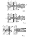
- Figures 6a to 6c and 7a to 7c show various important phases of a Injection molding cycle.
- FIG. 6a shows the first phase of a squeeze-aggression cycle.
- the mold halves 12 and 23 are in an open position and at the beginning of the closing phase (arrow 50).
- Of the Rotary valve 73 is in closed position.
- the injection screw 43 leads according to the dosing a rotary and an axial return movement through, so that in the screw antechamber 72 to a precisely calculated dosage liquid melt can be provided.
- the closed position of the Rotary valve has the great advantage that the required amount of weight with high Accuracy can be prepared because both pressure (P) and temperature (T) of the Melt as well as the volume in the screw anteroom exactly defined can be provided.
- the shutter is usually just at the beginning of one Production series closed and remains open thereafter.
- FIG. 6b shows the normal injection phase with the mold closed.
- the Injection screw 43 performs a pure axial movement and pushes in the Schneckenvorraum provided amount of spray mass on the nozzle tip and the sprue area in the cavity.
- the injection process requires only relatively small Compression values.
- the pressure buildup for the embossing phase is in the final phase of the Injection started.
- FIG. 6c shows the end position of the embossing phase or the Beginning of the cutting process.
- the central opening in the data carrier 60 is only Approaching indicated by the above stamp edge.
- the sprue 81 ( Figure 7c) is at the end of the cutting process not yet completely solidified. It is important that the stamp movement with the required effort, the volume to be displaced in the sprue area is still sufficiently fluid and fed back into the antechamber can be pressed.
- FIG. 7a shows the embossing and cooling phase and the cutting process completely finished.
- the sprue is ready, and the mold halves are still in closed position.
- the sprue 81 is in the holding space 54 with the undercut 56 held.
- the injection screw can according to Figure 7b already the next Prepare dosing process, with the shutter 73 remains open.
- FIG. 7c shows the last portion of a spray phase prior to removal, e.g. a finished CD (arrow 83) with a central opening 61 of the highest quality.
- a finished CD arrow 83
Landscapes
- Engineering & Computer Science (AREA)
- Manufacturing & Machinery (AREA)
- Mechanical Engineering (AREA)
- Moulds For Moulding Plastics Or The Like (AREA)
- Diaphragms For Electromechanical Transducers (AREA)
- Casting Or Compression Moulding Of Plastics Or The Like (AREA)
- Injection Moulding Of Plastics Or The Like (AREA)
Claims (11)
- Procédé de fabrication automatique de plaques minces, notamment de supports de données optiques (80) ou de CD dotés d'un orifice central, les deux demi-moules étant positionnés respectivement pour une position de départ d'un cycle d'injection pour la phase d'injection, une quantité dosée de résine étant injectée par une buse d'injection, le passage pour l'orifice central étant généré par un déplacement d'un poinçon à la fin de la phase d'injection pendant la phase de refroidissement mais avant une consolidation totale de la zone d'attaque de coulée, par la réduction du volume d'attaque de coulée, la pièce moulée étant refroidie jusqu'à ce qu'elle ait atteint une solidité de prélèvement suffisante et la plaque fabriquée ainsi que l'attaque de coulée comprenant la partie d'orifice central étant retirées des demi-moules,
caractérisé en ce que
le passage pour l'orifice central (61) est généré à la fin de la phase de compression finale ou de la phase d'estampage par le reflux dans l'antichambre de la vis (42, 72) et la phase de dosage pour le cycle d'injection respectivement consécutif démarre à la fin du déplacement du poinçon (51) pour le passage de l'orifice central, la masse de reflux provenant de la réduction du volume d'attaque de coulée pour la quantité de dosage étant prise en compte. - Procédé selon la revendication 1,
caractérisé en ce que
pour produire l'orifice central (61), le poinçon est déplacé en direction d'un orifice du type matrice et à distance de celui-ci et est guidé dans le moule de façon temporelle et/ou en fonction de la température de la masse fondue et/ou en fonction de la pression. - Procédé selon l'une quelconque des revendications 1 ou 2,
caractérisé en ce que
la buse d'injection (7) reste toujours ouverte pendant la production et la buse reste de préférence pressée contre l'outil d'injection. - Procédé selon l'une quelconque des revendications 1 à 3,
caractérisé en ce que
des moyens d'entraínement pouvant être commandés sont associés au poinçon (51) ainsi qu'à un boulon éjecteur (53) guidé dans le poinçon (51) pour l'attaque de coulée, sachant quepour le réglage d'une position de moulage, le poinçon (51) pourvu du boulon éjecteur (53) en retrait est positionné en dépassant légèrement de la cavité de moule,le poinçon (51), pour se déplacer jusqu'à s'enfoncer légèrement dans un orifice de type matrice, est pressé sur le côté d'injection du moule,et le déplacement de retrait du poinçon (51) s'effectue de préférence au cours de l'ouverture du moule, après que l'attaque de coulée se soit suffisamment refroidie et consolidée. - Procédé selon l'une quelconque des revendications 1 à 4,
caractérisé en ce que
le poinçon (51), lorsque le boulon éjecteur (53) est en retrait, forme avec une contre-dépouille (56) dans le poinçon (51) un espace de retenue (54) pour l'attaque de coulée, dans lequel l'attaque de coulée est saisie après une consolidation suffisante et est à nouveau éjectée après que le moule ait été ouvert, par l'actionnement du boulon éjecteur (53). - Procédé selon l'une quelconque des revendications 1 à 5,
caractérisé en ce que
la buse d'injection (7) est conçue de manière à pouvoir être fermée, le premier dosage étant réalisé au démarrage d'une nouvelle production lorsque la buse est fermée et les cycles de production consécutifs étant réalisés lorsque la buse est ouverte de façon permanente. - Dispositif de fabrication automatique de plaques minces, notamment de supports de données optiques (60) ou de CD, dotés d'un orifice central (61), par le procédé selon l'une quelconque des revendications 1 à 6, le dispositif comportant une machine de moulage par injection (10) pourvue au moins d'un demi-moule mobile (23) ; de moyens de commande destinés à commander de façon cyclique la fermeture du moule, l'injection, la phase de refroidissement et la phase de dosage pour le prochain cycle ainsi que le prélèvement des produits fabriqués ; d'un poinçon pour produire l'orifice central (61), qui peut se déplacer en direction de l'orifice du type matrice et à distance de celui-ci, les moyens de commande étant conçus pour réaliser le déplacement du poinçon pendant la phase de refroidissement, mais avant une consolidation complète de la zone d'attaque de coulée, caractérisé en ce que les moyens de commande sont conçus pour réaliser le déplacement du poinçon, à la fin de la phase de compression finale ou de la phase d'estampage, les moyens de commande étant dimensionnés de telle sorte que la phase de dosage pour le cycle d'injection respectivement suivant démarre à la fin du déplacement du poinçon (51) pour le passage de l'orifice central, et la masse de reflux provenant de la réduction du volume d'attaque de coulée pour la quantité de dosage étant prise en compte.
- Dispositif selon la revendication 7,
caractérisé en ce qu'il comprend un demi-moule fixe (12) ainsi qu'un demi-moule mobile (23), le poinçon (51) pourvu du boulon éjecteur (53) étant disposé sur le côté du demi-moule mobile (23) et la buse d'injection (7) sur le côté du demi-moule fixe (12). - Dispositif selon l'une quelconque des revendications 7 ou 8,
caractérisé en ce que
la buse (7) comprend une fermeture, notamment une fermeture à pointeau, à tiroir rotatif où à tiroir à fiche (73), pour mettre à disposition une quantité dosée de masse fondue liquide sous pression contrôlée. - Dispositif selon l'une quelconque des revendications 7 à 9,
caractérisé en ce que
le corps de fermeture (73) comprend à l'état ouvert une section de passage libre sans perturbation du fluage entre l'antichambre de la vis (47, 72) et la cavité (24) du moule d'injection. - Dispositif selon l'une quelconque des revendications 7 à 10,
caractérisé en ce que
la fermeture (73) est conçue comme une soupape de démarrage commandée, de telle sorte qu'au premier lancement d'une nouvelle série de production, la fermeture (73) reste fermée pendant la première phase de dosage, reste ouverte en permanence pour les cycles de production normaux consécutifs et la buse (7) reste de préférence pressée en permanence contre l'outil.
Applications Claiming Priority (3)
| Application Number | Priority Date | Filing Date | Title |
|---|---|---|---|
| CH16212001 | 2001-08-31 | ||
| CH162101 | 2001-08-31 | ||
| PCT/CH2002/000423 WO2003020491A1 (fr) | 2001-08-31 | 2002-07-26 | Procede et dispositif de production automatique de plaques minces |
Publications (2)
| Publication Number | Publication Date |
|---|---|
| EP1420930A1 EP1420930A1 (fr) | 2004-05-26 |
| EP1420930B1 true EP1420930B1 (fr) | 2005-11-23 |
Family
ID=4565679
Family Applications (1)
| Application Number | Title | Priority Date | Filing Date |
|---|---|---|---|
| EP02747131A Expired - Lifetime EP1420930B1 (fr) | 2001-08-31 | 2002-07-26 | Procede et dispositif de production automatique de plaques minces |
Country Status (5)
| Country | Link |
|---|---|
| EP (1) | EP1420930B1 (fr) |
| CN (1) | CN1549766A (fr) |
| AT (1) | ATE310625T1 (fr) |
| DE (1) | DE50205054D1 (fr) |
| WO (1) | WO2003020491A1 (fr) |
Families Citing this family (8)
| Publication number | Priority date | Publication date | Assignee | Title |
|---|---|---|---|---|
| DE102005041796A1 (de) * | 2005-09-02 | 2007-03-08 | BSH Bosch und Siemens Hausgeräte GmbH | Gefäß für ein Haushaltsgerät sowie Verfahren und Spritzgussform zu dessen Herstellung |
| JP2009073185A (ja) * | 2007-08-29 | 2009-04-09 | Meiki Co Ltd | 薄板成形品の成形金型 |
| ES2436798T3 (es) * | 2008-02-21 | 2014-01-07 | Netstal-Maschinen Ag | Procedimiento de moldeo por inyección con compresión y dispositivo para preformas |
| CN101856676A (zh) * | 2010-06-18 | 2010-10-13 | 上海交通大学 | 基于挤压螺旋线型带材展开的薄板生产方法 |
| CN102092119B (zh) * | 2010-12-22 | 2013-05-29 | 吉林大学珠海学院 | 针形自锁式喷嘴装置 |
| CN104191579B (zh) * | 2014-08-29 | 2016-07-13 | 苏州正豪塑胶电子有限公司 | 模具注塑控制装置 |
| DE102014014385A1 (de) * | 2014-10-02 | 2016-04-07 | Zimmermann Formenbau Gmbh | Lochformer zum Einsetzen in Spritzgussformen |
| CN113878789A (zh) * | 2021-09-08 | 2022-01-04 | 贝隆精密科技股份有限公司 | 一种缩短小型注塑件生产周期的生产方法 |
Family Cites Families (4)
| Publication number | Priority date | Publication date | Assignee | Title |
|---|---|---|---|---|
| JP2707676B2 (ja) * | 1989-01-27 | 1998-02-04 | 松下電器産業株式会社 | 成形金型 |
| JP3108229B2 (ja) * | 1992-11-13 | 2000-11-13 | 株式会社名機製作所 | ディスク成形用射出圧縮金型装置 |
| TW245680B (fr) * | 1993-04-12 | 1995-04-21 | Sankyo Kasei Kk | |
| EP1101593B1 (fr) * | 1997-07-07 | 2004-09-15 | Toyo Machinery & Metal Co. Ltd. | Machine à mouler par injection actionnée électriquement et procédé de moulage par injection |
-
2002
- 2002-07-26 EP EP02747131A patent/EP1420930B1/fr not_active Expired - Lifetime
- 2002-07-26 WO PCT/CH2002/000423 patent/WO2003020491A1/fr not_active Application Discontinuation
- 2002-07-26 AT AT02747131T patent/ATE310625T1/de not_active IP Right Cessation
- 2002-07-26 DE DE50205054T patent/DE50205054D1/de not_active Expired - Lifetime
- 2002-07-26 CN CNA028169751A patent/CN1549766A/zh active Pending
Also Published As
| Publication number | Publication date |
|---|---|
| WO2003020491A1 (fr) | 2003-03-13 |
| EP1420930A1 (fr) | 2004-05-26 |
| ATE310625T1 (de) | 2005-12-15 |
| CN1549766A (zh) | 2004-11-24 |
| DE50205054D1 (de) | 2005-12-29 |
Similar Documents
| Publication | Publication Date | Title |
|---|---|---|
| DE69416356T2 (de) | Vorrichtung und Verfahren zum Spritzgiessen mit örtlicher Druckbeaufschlagung | |
| CH342368A (de) | Verfahren und Maschine zur Herstellung von Flaschen aus plastischem Material | |
| DE3780151T2 (de) | Spritzgiesseinrichtung und verfahren. | |
| DE1142058B (de) | Verfahren zur Verarbeitung thermoplastischer Kunststoffe in einer Spritzgiessmaschine | |
| EP0744266B1 (fr) | Procédé et dispositif pour mouler par injection des corps creux soufflés en matière plastique | |
| DE69104587T2 (de) | Verfahren zum steuern des arbeitszyklus einer spritzgiessmaschine. | |
| EP1254006B1 (fr) | Procede de commande/regulation du processus d'estampage ainsi que dispositif d'entrainement et de commande d'outils de moulage par injection | |
| DE69418562T2 (de) | Vorrichtung zum Formen von Kunststoffen | |
| EP1420930B1 (fr) | Procede et dispositif de production automatique de plaques minces | |
| DE3937099C2 (de) | Antrieb für eine Plastifizier- und Einspritzeinheit einer Spritzgießmaschine | |
| EP0074473B1 (fr) | Procédé et dispositif pour la fabrication de pièces de forme ou des objets en matière plastique | |
| EP0846050B1 (fr) | Presse de moulage par injection avec systeme a canal chauffant integre | |
| DE19639678B4 (de) | Formwerkzeug für den Einsatz in einer Spritzgussmaschine und Verfahren | |
| EP1343621B1 (fr) | Procede et dispositif pour le moulage par injection de supports de donnees optiques plats ayant un poids precis | |
| EP1912773B1 (fr) | Procede, unite de commande pour une machine, et produit programme d'ordinateur pour commander une machine servant a produire une piece moulee, en particulier procede de moulage par injection | |
| DE68901902T2 (de) | Verfahren zur formenherstellung von gegenstaenden, mittel im hinblick auf die durchfuehrung dieses verfahrens und beabsichtigte einrichtungen fuer diese mittel. | |
| DE102005053735B4 (de) | Spritzgießwerkzeug | |
| DE19651879C2 (de) | Verfahren zur Aufbringung des Nachdrucks bei der Herstellung von Spritzlingen | |
| EP0489363A1 (fr) | Procédé de moulage par injection de pièces en matière plastique et dispositif pour la mise en oeuvre de ce procédé | |
| EP2252446B1 (fr) | Procédé et dispositif de moulage par injection-compression de préformes | |
| DE4221423C2 (de) | Verfahren und Vorrichtung zum Herstellen von Gegenständen aus thermoplastischem Kunststoff durch Spritzgießen | |
| DE19846710A1 (de) | Verfahren zum Spritzgießen von Mikroformteilen aus thermoplast. Kunststoffen mit geringer Angußmasse | |
| DE19617768C2 (de) | Verfahren und Vorrichtung zum Spritzgießen von Kunststoffteilen | |
| DE1124234B (de) | Spritzgussmaschine zur Verarbeitung thermoplastischer Kunststoffe | |
| WO2009103805A1 (fr) | Procédé et dispositif de moulage par injection-compression de préformes |
Legal Events
| Date | Code | Title | Description |
|---|---|---|---|
| PUAI | Public reference made under article 153(3) epc to a published international application that has entered the european phase |
Free format text: ORIGINAL CODE: 0009012 |
|
| 17P | Request for examination filed |
Effective date: 20040112 |
|
| AK | Designated contracting states |
Kind code of ref document: A1 Designated state(s): AT BE BG CH CY CZ DE DK EE ES FI FR GB GR IE IT LI LU MC NL PT SE SK TR |
|
| AX | Request for extension of the european patent |
Extension state: AL LT LV MK RO SI |
|
| 17Q | First examination report despatched |
Effective date: 20040922 |
|
| GRAP | Despatch of communication of intention to grant a patent |
Free format text: ORIGINAL CODE: EPIDOSNIGR1 |
|
| GRAS | Grant fee paid |
Free format text: ORIGINAL CODE: EPIDOSNIGR3 |
|
| GRAA | (expected) grant |
Free format text: ORIGINAL CODE: 0009210 |
|
| AK | Designated contracting states |
Kind code of ref document: B1 Designated state(s): AT BE BG CH CY CZ DE DK EE ES FI FR GB GR IE IT LI LU MC NL PT SE SK TR |
|
| PG25 | Lapsed in a contracting state [announced via postgrant information from national office to epo] |
Ref country code: IT Free format text: LAPSE BECAUSE OF FAILURE TO SUBMIT A TRANSLATION OF THE DESCRIPTION OR TO PAY THE FEE WITHIN THE PRESCRIBED TIME-LIMIT;WARNING: LAPSES OF ITALIAN PATENTS WITH EFFECTIVE DATE BEFORE 2007 MAY HAVE OCCURRED AT ANY TIME BEFORE 2007. THE CORRECT EFFECTIVE DATE MAY BE DIFFERENT FROM THE ONE RECORDED. Effective date: 20051123 Ref country code: CZ Free format text: LAPSE BECAUSE OF FAILURE TO SUBMIT A TRANSLATION OF THE DESCRIPTION OR TO PAY THE FEE WITHIN THE PRESCRIBED TIME-LIMIT Effective date: 20051123 Ref country code: FI Free format text: LAPSE BECAUSE OF FAILURE TO SUBMIT A TRANSLATION OF THE DESCRIPTION OR TO PAY THE FEE WITHIN THE PRESCRIBED TIME-LIMIT Effective date: 20051123 Ref country code: NL Free format text: LAPSE BECAUSE OF FAILURE TO SUBMIT A TRANSLATION OF THE DESCRIPTION OR TO PAY THE FEE WITHIN THE PRESCRIBED TIME-LIMIT Effective date: 20051123 Ref country code: IE Free format text: LAPSE BECAUSE OF FAILURE TO SUBMIT A TRANSLATION OF THE DESCRIPTION OR TO PAY THE FEE WITHIN THE PRESCRIBED TIME-LIMIT Effective date: 20051123 Ref country code: SK Free format text: LAPSE BECAUSE OF FAILURE TO SUBMIT A TRANSLATION OF THE DESCRIPTION OR TO PAY THE FEE WITHIN THE PRESCRIBED TIME-LIMIT Effective date: 20051123 Ref country code: GB Free format text: LAPSE BECAUSE OF FAILURE TO SUBMIT A TRANSLATION OF THE DESCRIPTION OR TO PAY THE FEE WITHIN THE PRESCRIBED TIME-LIMIT Effective date: 20051123 |
|
| REG | Reference to a national code |
Ref country code: GB Ref legal event code: FG4D Free format text: NOT ENGLISH |
|
| REG | Reference to a national code |
Ref country code: CH Ref legal event code: EP |
|
| REF | Corresponds to: |
Ref document number: 50205054 Country of ref document: DE Date of ref document: 20051229 Kind code of ref document: P |
|
| REG | Reference to a national code |
Ref country code: IE Ref legal event code: FG4D Free format text: LANGUAGE OF EP DOCUMENT: GERMAN |
|
| PG25 | Lapsed in a contracting state [announced via postgrant information from national office to epo] |
Ref country code: DK Free format text: LAPSE BECAUSE OF FAILURE TO SUBMIT A TRANSLATION OF THE DESCRIPTION OR TO PAY THE FEE WITHIN THE PRESCRIBED TIME-LIMIT Effective date: 20060223 Ref country code: GR Free format text: LAPSE BECAUSE OF FAILURE TO SUBMIT A TRANSLATION OF THE DESCRIPTION OR TO PAY THE FEE WITHIN THE PRESCRIBED TIME-LIMIT Effective date: 20060223 Ref country code: BG Free format text: LAPSE BECAUSE OF FAILURE TO SUBMIT A TRANSLATION OF THE DESCRIPTION OR TO PAY THE FEE WITHIN THE PRESCRIBED TIME-LIMIT Effective date: 20060223 Ref country code: SE Free format text: LAPSE BECAUSE OF FAILURE TO SUBMIT A TRANSLATION OF THE DESCRIPTION OR TO PAY THE FEE WITHIN THE PRESCRIBED TIME-LIMIT Effective date: 20060223 |
|
| PG25 | Lapsed in a contracting state [announced via postgrant information from national office to epo] |
Ref country code: ES Free format text: LAPSE BECAUSE OF FAILURE TO SUBMIT A TRANSLATION OF THE DESCRIPTION OR TO PAY THE FEE WITHIN THE PRESCRIBED TIME-LIMIT Effective date: 20060306 |
|
| REG | Reference to a national code |
Ref country code: CH Ref legal event code: NV Representative=s name: ERNST ACKERMANN PATENTANWALT |
|
| PG25 | Lapsed in a contracting state [announced via postgrant information from national office to epo] |
Ref country code: PT Free format text: LAPSE BECAUSE OF FAILURE TO SUBMIT A TRANSLATION OF THE DESCRIPTION OR TO PAY THE FEE WITHIN THE PRESCRIBED TIME-LIMIT Effective date: 20060424 |
|
| NLV1 | Nl: lapsed or annulled due to failure to fulfill the requirements of art. 29p and 29m of the patents act | ||
| GBV | Gb: ep patent (uk) treated as always having been void in accordance with gb section 77(7)/1977 [no translation filed] |
Effective date: 20051123 |
|
| REG | Reference to a national code |
Ref country code: IE Ref legal event code: FD4D |
|
| PG25 | Lapsed in a contracting state [announced via postgrant information from national office to epo] |
Ref country code: MC Free format text: LAPSE BECAUSE OF NON-PAYMENT OF DUE FEES Effective date: 20060731 Ref country code: BE Free format text: LAPSE BECAUSE OF NON-PAYMENT OF DUE FEES Effective date: 20060731 |
|
| PLBE | No opposition filed within time limit |
Free format text: ORIGINAL CODE: 0009261 |
|
| STAA | Information on the status of an ep patent application or granted ep patent |
Free format text: STATUS: NO OPPOSITION FILED WITHIN TIME LIMIT |
|
| PG25 | Lapsed in a contracting state [announced via postgrant information from national office to epo] |
Ref country code: FR Free format text: LAPSE BECAUSE OF FAILURE TO SUBMIT A TRANSLATION OF THE DESCRIPTION OR TO PAY THE FEE WITHIN THE PRESCRIBED TIME-LIMIT Effective date: 20061020 |
|
| 26N | No opposition filed |
Effective date: 20060824 |
|
| EN | Fr: translation not filed | ||
| PG25 | Lapsed in a contracting state [announced via postgrant information from national office to epo] |
Ref country code: AT Free format text: LAPSE BECAUSE OF NON-PAYMENT OF DUE FEES Effective date: 20060726 |
|
| PGFP | Annual fee paid to national office [announced via postgrant information from national office to epo] |
Ref country code: CH Payment date: 20070713 Year of fee payment: 6 |
|
| BERE | Be: lapsed |
Owner name: NETSTAL-MASCHINEN A.G. Effective date: 20060731 |
|
| PG25 | Lapsed in a contracting state [announced via postgrant information from national office to epo] |
Ref country code: EE Free format text: LAPSE BECAUSE OF FAILURE TO SUBMIT A TRANSLATION OF THE DESCRIPTION OR TO PAY THE FEE WITHIN THE PRESCRIBED TIME-LIMIT Effective date: 20051123 |
|
| PG25 | Lapsed in a contracting state [announced via postgrant information from national office to epo] |
Ref country code: TR Free format text: LAPSE BECAUSE OF FAILURE TO SUBMIT A TRANSLATION OF THE DESCRIPTION OR TO PAY THE FEE WITHIN THE PRESCRIBED TIME-LIMIT Effective date: 20051123 Ref country code: LU Free format text: LAPSE BECAUSE OF NON-PAYMENT OF DUE FEES Effective date: 20060726 |
|
| PG25 | Lapsed in a contracting state [announced via postgrant information from national office to epo] |
Ref country code: FR Free format text: LAPSE BECAUSE OF FAILURE TO SUBMIT A TRANSLATION OF THE DESCRIPTION OR TO PAY THE FEE WITHIN THE PRESCRIBED TIME-LIMIT Effective date: 20051123 Ref country code: CY Free format text: LAPSE BECAUSE OF FAILURE TO SUBMIT A TRANSLATION OF THE DESCRIPTION OR TO PAY THE FEE WITHIN THE PRESCRIBED TIME-LIMIT Effective date: 20051123 |
|
| REG | Reference to a national code |
Ref country code: CH Ref legal event code: PL |
|
| PG25 | Lapsed in a contracting state [announced via postgrant information from national office to epo] |
Ref country code: CH Free format text: LAPSE BECAUSE OF NON-PAYMENT OF DUE FEES Effective date: 20080731 Ref country code: LI Free format text: LAPSE BECAUSE OF NON-PAYMENT OF DUE FEES Effective date: 20080731 |
|
| PGFP | Annual fee paid to national office [announced via postgrant information from national office to epo] |
Ref country code: DE Payment date: 20100723 Year of fee payment: 9 |
|
| PG25 | Lapsed in a contracting state [announced via postgrant information from national office to epo] |
Ref country code: DE Free format text: LAPSE BECAUSE OF NON-PAYMENT OF DUE FEES Effective date: 20120201 |
|
| REG | Reference to a national code |
Ref country code: DE Ref legal event code: R119 Ref document number: 50205054 Country of ref document: DE Effective date: 20120201 |