EP1420712B1 - Medizinisches oder dentalmedizinisches handstück mit einem in einem wälzlager gelagerten drehteil - Google Patents
Medizinisches oder dentalmedizinisches handstück mit einem in einem wälzlager gelagerten drehteil Download PDFInfo
- Publication number
- EP1420712B1 EP1420712B1 EP02797574A EP02797574A EP1420712B1 EP 1420712 B1 EP1420712 B1 EP 1420712B1 EP 02797574 A EP02797574 A EP 02797574A EP 02797574 A EP02797574 A EP 02797574A EP 1420712 B1 EP1420712 B1 EP 1420712B1
- Authority
- EP
- European Patent Office
- Prior art keywords
- ring
- bearing
- handpiece
- ring groove
- handpiece according
- Prior art date
- Legal status (The legal status is an assumption and is not a legal conclusion. Google has not performed a legal analysis and makes no representation as to the accuracy of the status listed.)
- Expired - Lifetime
Links
- 238000005096 rolling process Methods 0.000 description 57
- 230000008878 coupling Effects 0.000 description 35
- 238000010168 coupling process Methods 0.000 description 35
- 238000005859 coupling reaction Methods 0.000 description 35
- 230000033001 locomotion Effects 0.000 description 8
- 230000002093 peripheral effect Effects 0.000 description 6
- 238000007789 sealing Methods 0.000 description 5
- 238000003780 insertion Methods 0.000 description 4
- 230000037431 insertion Effects 0.000 description 4
- 238000006073 displacement reaction Methods 0.000 description 3
- 230000002349 favourable effect Effects 0.000 description 3
- 239000000463 material Substances 0.000 description 3
- 238000005192 partition Methods 0.000 description 3
- XLYOFNOQVPJJNP-UHFFFAOYSA-N water Substances O XLYOFNOQVPJJNP-UHFFFAOYSA-N 0.000 description 3
- 238000010276 construction Methods 0.000 description 2
- 230000000694 effects Effects 0.000 description 2
- 239000007921 spray Substances 0.000 description 2
- 239000003570 air Substances 0.000 description 1
- 210000003484 anatomy Anatomy 0.000 description 1
- 239000011324 bead Substances 0.000 description 1
- 230000005540 biological transmission Effects 0.000 description 1
- 230000006835 compression Effects 0.000 description 1
- 238000007906 compression Methods 0.000 description 1
- 238000011161 development Methods 0.000 description 1
- 230000018109 developmental process Effects 0.000 description 1
- 239000013013 elastic material Substances 0.000 description 1
- 238000009434 installation Methods 0.000 description 1
- 239000002184 metal Substances 0.000 description 1
- 239000000203 mixture Substances 0.000 description 1
- 230000035515 penetration Effects 0.000 description 1
- 125000006850 spacer group Chemical group 0.000 description 1
- 230000003313 weakening effect Effects 0.000 description 1
Images


Classifications
-
- F—MECHANICAL ENGINEERING; LIGHTING; HEATING; WEAPONS; BLASTING
- F16—ENGINEERING ELEMENTS AND UNITS; GENERAL MEASURES FOR PRODUCING AND MAINTAINING EFFECTIVE FUNCTIONING OF MACHINES OR INSTALLATIONS; THERMAL INSULATION IN GENERAL
- F16F—SPRINGS; SHOCK-ABSORBERS; MEANS FOR DAMPING VIBRATION
- F16F1/00—Springs
- F16F1/36—Springs made of rubber or other material having high internal friction, e.g. thermoplastic elastomers
- F16F1/373—Springs made of rubber or other material having high internal friction, e.g. thermoplastic elastomers characterised by having a particular shape
- F16F1/3732—Springs made of rubber or other material having high internal friction, e.g. thermoplastic elastomers characterised by having a particular shape having an annular or the like shape, e.g. grommet-type resilient mountings
-
- A—HUMAN NECESSITIES
- A61—MEDICAL OR VETERINARY SCIENCE; HYGIENE
- A61C—DENTISTRY; APPARATUS OR METHODS FOR ORAL OR DENTAL HYGIENE
- A61C1/00—Dental machines for boring or cutting ; General features of dental machines or apparatus, e.g. hand-piece design
- A61C1/02—Dental machines for boring or cutting ; General features of dental machines or apparatus, e.g. hand-piece design characterised by the drive of the dental tools
- A61C1/05—Dental machines for boring or cutting ; General features of dental machines or apparatus, e.g. hand-piece design characterised by the drive of the dental tools with turbine drive
-
- A—HUMAN NECESSITIES
- A61—MEDICAL OR VETERINARY SCIENCE; HYGIENE
- A61C—DENTISTRY; APPARATUS OR METHODS FOR ORAL OR DENTAL HYGIENE
- A61C1/00—Dental machines for boring or cutting ; General features of dental machines or apparatus, e.g. hand-piece design
- A61C1/02—Dental machines for boring or cutting ; General features of dental machines or apparatus, e.g. hand-piece design characterised by the drive of the dental tools
- A61C1/06—Dental machines for boring or cutting ; General features of dental machines or apparatus, e.g. hand-piece design characterised by the drive of the dental tools with electric drive
-
- A—HUMAN NECESSITIES
- A61—MEDICAL OR VETERINARY SCIENCE; HYGIENE
- A61C—DENTISTRY; APPARATUS OR METHODS FOR ORAL OR DENTAL HYGIENE
- A61C1/00—Dental machines for boring or cutting ; General features of dental machines or apparatus, e.g. hand-piece design
- A61C1/08—Machine parts specially adapted for dentistry
- A61C1/18—Flexible shafts; Clutches or the like; Bearings or lubricating arrangements; Drives or transmissions
- A61C1/181—Bearings or lubricating arrangements, e.g. air-cushion bearings
-
- F—MECHANICAL ENGINEERING; LIGHTING; HEATING; WEAPONS; BLASTING
- F16—ENGINEERING ELEMENTS AND UNITS; GENERAL MEASURES FOR PRODUCING AND MAINTAINING EFFECTIVE FUNCTIONING OF MACHINES OR INSTALLATIONS; THERMAL INSULATION IN GENERAL
- F16C—SHAFTS; FLEXIBLE SHAFTS; ELEMENTS OR CRANKSHAFT MECHANISMS; ROTARY BODIES OTHER THAN GEARING ELEMENTS; BEARINGS
- F16C27/00—Elastic or yielding bearings or bearing supports, for exclusively rotary movement
- F16C27/06—Elastic or yielding bearings or bearing supports, for exclusively rotary movement by means of parts of rubber or like materials
- F16C27/066—Ball or roller bearings
-
- F—MECHANICAL ENGINEERING; LIGHTING; HEATING; WEAPONS; BLASTING
- F16—ENGINEERING ELEMENTS AND UNITS; GENERAL MEASURES FOR PRODUCING AND MAINTAINING EFFECTIVE FUNCTIONING OF MACHINES OR INSTALLATIONS; THERMAL INSULATION IN GENERAL
- F16C—SHAFTS; FLEXIBLE SHAFTS; ELEMENTS OR CRANKSHAFT MECHANISMS; ROTARY BODIES OTHER THAN GEARING ELEMENTS; BEARINGS
- F16C35/00—Rigid support of bearing units; Housings, e.g. caps, covers
- F16C35/04—Rigid support of bearing units; Housings, e.g. caps, covers in the case of ball or roller bearings
- F16C35/06—Mounting or dismounting of ball or roller bearings; Fixing them onto shaft or in housing
- F16C35/07—Fixing them on the shaft or housing with interposition of an element
- F16C35/077—Fixing them on the shaft or housing with interposition of an element between housing and outer race ring
-
- F—MECHANICAL ENGINEERING; LIGHTING; HEATING; WEAPONS; BLASTING
- F16—ENGINEERING ELEMENTS AND UNITS; GENERAL MEASURES FOR PRODUCING AND MAINTAINING EFFECTIVE FUNCTIONING OF MACHINES OR INSTALLATIONS; THERMAL INSULATION IN GENERAL
- F16F—SPRINGS; SHOCK-ABSORBERS; MEANS FOR DAMPING VIBRATION
- F16F15/00—Suppression of vibrations in systems; Means or arrangements for avoiding or reducing out-of-balance forces, e.g. due to motion
- F16F15/02—Suppression of vibrations of non-rotating, e.g. reciprocating systems; Suppression of vibrations of rotating systems by use of members not moving with the rotating systems
- F16F15/04—Suppression of vibrations of non-rotating, e.g. reciprocating systems; Suppression of vibrations of rotating systems by use of members not moving with the rotating systems using elastic means
- F16F15/08—Suppression of vibrations of non-rotating, e.g. reciprocating systems; Suppression of vibrations of rotating systems by use of members not moving with the rotating systems using elastic means with rubber springs ; with springs made of rubber and metal
-
- F—MECHANICAL ENGINEERING; LIGHTING; HEATING; WEAPONS; BLASTING
- F16—ENGINEERING ELEMENTS AND UNITS; GENERAL MEASURES FOR PRODUCING AND MAINTAINING EFFECTIVE FUNCTIONING OF MACHINES OR INSTALLATIONS; THERMAL INSULATION IN GENERAL
- F16C—SHAFTS; FLEXIBLE SHAFTS; ELEMENTS OR CRANKSHAFT MECHANISMS; ROTARY BODIES OTHER THAN GEARING ELEMENTS; BEARINGS
- F16C19/00—Bearings with rolling contact, for exclusively rotary movement
- F16C19/02—Bearings with rolling contact, for exclusively rotary movement with bearing balls essentially of the same size in one or more circular rows
- F16C19/14—Bearings with rolling contact, for exclusively rotary movement with bearing balls essentially of the same size in one or more circular rows for both radial and axial load
- F16C19/18—Bearings with rolling contact, for exclusively rotary movement with bearing balls essentially of the same size in one or more circular rows for both radial and axial load with two or more rows of balls
-
- F—MECHANICAL ENGINEERING; LIGHTING; HEATING; WEAPONS; BLASTING
- F16—ENGINEERING ELEMENTS AND UNITS; GENERAL MEASURES FOR PRODUCING AND MAINTAINING EFFECTIVE FUNCTIONING OF MACHINES OR INSTALLATIONS; THERMAL INSULATION IN GENERAL
- F16C—SHAFTS; FLEXIBLE SHAFTS; ELEMENTS OR CRANKSHAFT MECHANISMS; ROTARY BODIES OTHER THAN GEARING ELEMENTS; BEARINGS
- F16C19/00—Bearings with rolling contact, for exclusively rotary movement
- F16C19/54—Systems consisting of a plurality of bearings with rolling friction
- F16C19/541—Systems consisting of juxtaposed rolling bearings including at least one angular contact bearing
- F16C19/542—Systems consisting of juxtaposed rolling bearings including at least one angular contact bearing with two rolling bearings with angular contact
-
- F—MECHANICAL ENGINEERING; LIGHTING; HEATING; WEAPONS; BLASTING
- F16—ENGINEERING ELEMENTS AND UNITS; GENERAL MEASURES FOR PRODUCING AND MAINTAINING EFFECTIVE FUNCTIONING OF MACHINES OR INSTALLATIONS; THERMAL INSULATION IN GENERAL
- F16C—SHAFTS; FLEXIBLE SHAFTS; ELEMENTS OR CRANKSHAFT MECHANISMS; ROTARY BODIES OTHER THAN GEARING ELEMENTS; BEARINGS
- F16C2240/00—Specified values or numerical ranges of parameters; Relations between them
- F16C2240/40—Linear dimensions, e.g. length, radius, thickness, gap
- F16C2240/70—Diameters; Radii
-
- F—MECHANICAL ENGINEERING; LIGHTING; HEATING; WEAPONS; BLASTING
- F16—ENGINEERING ELEMENTS AND UNITS; GENERAL MEASURES FOR PRODUCING AND MAINTAINING EFFECTIVE FUNCTIONING OF MACHINES OR INSTALLATIONS; THERMAL INSULATION IN GENERAL
- F16C—SHAFTS; FLEXIBLE SHAFTS; ELEMENTS OR CRANKSHAFT MECHANISMS; ROTARY BODIES OTHER THAN GEARING ELEMENTS; BEARINGS
- F16C2300/00—Application independent of particular apparatuses
- F16C2300/10—Application independent of particular apparatuses related to size
- F16C2300/12—Small applications, e.g. miniature bearings
-
- F—MECHANICAL ENGINEERING; LIGHTING; HEATING; WEAPONS; BLASTING
- F16—ENGINEERING ELEMENTS AND UNITS; GENERAL MEASURES FOR PRODUCING AND MAINTAINING EFFECTIVE FUNCTIONING OF MACHINES OR INSTALLATIONS; THERMAL INSULATION IN GENERAL
- F16C—SHAFTS; FLEXIBLE SHAFTS; ELEMENTS OR CRANKSHAFT MECHANISMS; ROTARY BODIES OTHER THAN GEARING ELEMENTS; BEARINGS
- F16C2316/00—Apparatus in health or amusement
- F16C2316/10—Apparatus in health or amusement in medical appliances, e.g. in diagnosis, dentistry, instruments, prostheses, medical imaging appliances
- F16C2316/13—Dental machines
-
- Y—GENERAL TAGGING OF NEW TECHNOLOGICAL DEVELOPMENTS; GENERAL TAGGING OF CROSS-SECTIONAL TECHNOLOGIES SPANNING OVER SEVERAL SECTIONS OF THE IPC; TECHNICAL SUBJECTS COVERED BY FORMER USPC CROSS-REFERENCE ART COLLECTIONS [XRACs] AND DIGESTS
- Y10—TECHNICAL SUBJECTS COVERED BY FORMER USPC
- Y10S—TECHNICAL SUBJECTS COVERED BY FORMER USPC CROSS-REFERENCE ART COLLECTIONS [XRACs] AND DIGESTS
- Y10S415/00—Rotary kinetic fluid motors or pumps
- Y10S415/904—Tool drive turbine, e.g. dental drill
Definitions
- the invention relates to a medical or dental handpiece according to the preamble of claim 1.
- a medical or dental handpiece is an article used to machine the human body or natural or artificial parts thereof, such as prostheses, with a tool.
- the tool in most embodiments, is a cutting tool that acts on the body in a rotary motion or in a reciprocating motion.
- the drive is a rotary motor, which can be arranged in the handpiece itself or in a so-called.
- Connector with which the handpiece by a plug-in coupling, in particular a plug / rotary coupling with a coupling recess on the one part and a coupling pin in the coupling recess the other part is releasably connected.
- the drive movement is derived from a rotational movement that executes at least one rotary part and this is rotatably mounted in the inner ring of the inner ring and an outer ring bearing bearing.
- a rotational movement that executes at least one rotary part and this is rotatably mounted in the inner ring of the inner ring and an outer ring bearing bearing.
- the document CH 690226 discloses a handpiece according to the preamble of claim 1.
- the invention has for its object to improve a medical or dental handpiece of the type specified in terms of the axial boundary of its rolling bearing or its outer and / or inner ring.
- a circlip is excellently such a circular cross-section, for which the term O-ring has established itself in the jargon.
- the side facing the respective rolling bearing ring is convex rounded. This is favorable when mounting the respective rolling bearing ring, because the circlip inherently forms with its rounded edges insertion surfaces, which ensure that when mounting the respective rolling bearing ring these insertion surfaces ensure automatic pushing away of the stationary ring portion of the retaining ring, wherein in the final assembly of the Circlip due to its elasticity automatically in the second annular groove.
- the arrangement may be such that only an axial securing exists to the effect that the respective rolling bearing ring is held captive axially.
- the inventive elastic support of the retaining ring on the respective shoulder surface also allows a defined axial positioning of the respective rolling bearing ring, although due to the elastically compressible material of the retaining ring no large axial forces can be absorbed, but this is not required in many storage cases.
- the positive engagement of the locking ring according to the invention in the second annular groove also allows a radially elastic mounting.
- a radial distance is provided between the rolling bearing ring and the bearing bush or the bearing journal, in the region of which a radial movement is ensured on account of the elasticity of the securing ring.
- FIG. 1 in its entirety designated 1 treatment instrument consists of a rear instrument part, namely a so-called connector part 2, and a front part of the instrument, namely the so-called handpiece 3, by a coupling 4 in particular a plug-in coupling, preferably a plug / rotary coupling, releasably connected together are.
- a holding device 5 is arranged for a tool 6 at the front end of the treatment instrument 1, wherein the tool 6 can protrude laterally or forwards.
- the handpiece 3 can straight (not shown) or to the tool 6 side facing away curved (dash-dotted lines indicated) or extend angularly.
- the plug-in / rotary coupling is formed by a circular cross-section coupling recess 7 and a therein plugged in with little play coupling pin 8.
- the coupling recess 7 is arranged at the rear end of the handpiece 3, and the substantially cylindrical coupling pin 8 extends from the connecting part 2 to the front.
- a latching device 9 This has a latching element 9a, which is radially movably mounted in the one coupling part and is biased by a spring force into a latching position passing through the dividing joint, in which the latching element 9a engages in an annular groove in the other coupling part.
- Such a latching device 9 is automatically locked by a dome during manual coupling and manual axial Buchraftausübung when uncoupling, the latching element 9a is automatically displaced into its release position.
- the connecting part 2 is connected to a flexible supply line 2 a, which is connected to a control unit, not shown.
- the handpiece 3 is preferably freely rotatably mounted on the coupling pin 8, whereby the handling is improved.
- plug / twist coupling 4 extends at least one media line 11 for a treatment or drive medium, for.
- the media line 11 may extend axially through a radial pitch joint (not shown) or Z-shaped through a hollow cylindrical pitch between the coupling recess 7 and the coupling pin 8, wherein the media line 11, the dividing joint in the region of an annular groove in the coupling pin 8 or in the coupling recess.
- the media line 11 extends from the rear end of the treatment instrument 1 to its front end portion, where it may extend partially as a channel in the instrument body or as a hose or pipe.
- the media line 11 opens out in the front end region of the treatment instrument 1 from this, said mouth opening 11 a is directed to the treatment site or on the tip of the tool 6.
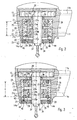
- the handpiece 3 has a rotatably mounted therein in a rolling bearing rotary member 12.
- a rolling bearing rotary member 12 This may be a one-piece or consist of a rear or front shaft portion 13a, 13b, which are fixedly connected to each other at the beginning of the arc or at the apex of the angle.
- a turbine T is arranged with a turbine wheel 15, which extends around a transversely to the shaft 13 and to its longitudinal central axis 13 c and in the angular or bottom plane of the shaft 13
- Rotary shaft 16 is rotatably mounted in the head 14.
- the turbine wheel 15 is located in a turbine chamber 17, into which a media line 11b for compressed air opens and is directed onto the blades of the turbine wheel 15.
- the media line 11b passes through the plug / rotary coupling 4 also Z-shaped.
- the turbine wheel 15 is connected to the holding device 5, here with a receiving sleeve 18, in which the tool 6 with its shaft can be inserted and releasably fixed in a conventional manner by a fixing device.
- the turbine wheel 15 and the receiving sleeve 18 may be integrally formed.
- Fig. 1 is the turbine wheel 15 in the plug-in opening 18a facing away from the end portion of the receiving sleeve 18 connected thereto.
- turbine rotor 15a is one or two juxtaposed rolling bearings 21 (FIG. Fig. 2 ) provided with an outer ring 21a and an inner ring 21b and arranged therebetween rolling elements, in particular balls, with which the turbine rotor 15a is rotatably mounted in a arranged in the housing 14 of the head bearing bushing 23 about the axis of rotation 16.
- each rolling bearing 21 in the bearing bush 23 is associated with a securing device 20 with a locking ring 24 made of elastically deformable or elastically compressible material, which is so deep in an annular groove 25 in the inner circumferential surface 23a of the bearing bush 23, that he the inner circumferential surface 23a projects beyond and thus forms a securing bead, with which it radially in one of the annular groove 25 opposite Ring groove 26 in the outer circumferential surface 21c of the roller bearing outer ring 21a sits.
- the circlip 24 presses radially inwardly toward the bottom of the annular groove 26 with, for example, a small elastic bias.
- the inner diameter of the circlip 24 is made smaller than the inner diameter of the annular groove 26 and / or by half the difference between the inner diameter of the annular groove 26 and the outer diameter of the annular groove 25 is dimensioned slightly smaller than the diameter of the cross-section preferably round retaining ring 24.
- the locking ring 24 is resiliently biased radially inwardly against the bottom of the annular groove 26.
- the axial width of the annular grooves 25,26 is slightly smaller than the axial dimension of the retaining ring 24 so that it is elastically compressed between the side walls or flanks 26a of the annular groove 25,26.
- the cross-sectional shape of the annular groove 25 is quadrangular and the cross-sectional shape of the annular groove 26 is rounded in a circular arc section.
- other cross-sectional shapes are possible.
- the rolling bearings 21 at least on one end face a rounded or acute-angled insertion surface 27, the circlip 24 automatically elastically deforms during axial insertion of the rolling bearing 21 in the bearing bush 23 and this springs automatically in the mounting position again in the annular groove 26.
- an introduction surface 27 is provided on both end faces.
- the annular groove 26 with respect to the grooves of the rolling elements 22 axially offset, whereby the material weakening of the roller bearing outer ring 21a is of lesser or no effect.
- the rolling bearings 21 are made the same so that a rolling bearing 21 optionally fits on one or the other bearing, e.g. in a position rotated by 180 °.
- annular grooves 25 are thus each arranged with a retaining ring 24 in the bearing bush 23, whose axial center distance a from one another is greater than the axial width of a rolling bearing 21, wherein the annular grooves 26 are arranged in the opposite end portions of the rolling bearings 21.
- they can also be centered or inwardly offset with respect to the roller bearings 21 or arranged offset in two rolling bearings 21 in an axial direction.
- the annular groove 26 may be designed to be axially outflowing towards one side, as is the embodiment to be described later Fig. 3 shows in itself.
- the mutually facing edges 26a of the annular groove 26 adapted to the axial distance of the existing retaining rings 24 and preferably so that the retaining rings 24 press with an elastic tension or compression against the preferably convergent flanks 26a.
- the embodiment according to Fig. 3 differs from the exemplary embodiment Fig. 2 in that the roller bearing outer rings 21a are not received in a closing manner with a conventional roller bearing fit in the bushing 23, but have a radial circumferential distance b from the inner circumferential surface 23a.
- the bearing is elastically yielding not only in the axial direction but also in the radial direction, so that the turbine rotor 15a can yield either axially or axially and radially elastically and is therefore axially or radially elastically damped.
- Another advantage here is the simplified design and assembly and disassembly, in which the retaining rings 24 after a displacement and deformation from their safety position automatically recover and snap back into their safety position without having to be solved and set again, as it was usual metal circlips is the case.
- the rolling bearings 21 are each arranged at an axial distance from associated components of the head housing, so that the above-described axial compliance is not limited. If the axial compliance is desired only in one axial direction, the respective rolling bearing ring in the other axial direction may be limited by a contact surface.
- annular seal 29 between the receiving sleeve 18 and a partition wall 31 between the turbine chamber 32 and the inner space 33 of the liner 23 is provided.
- This may be a known sealing ring, which is received in an annular groove of the partition wall 31.
- a corresponding annular seal 34 may also be arranged between the receiving sleeve 18 and an end wall 35 of the head housing, which is used or screwed in the embodiment in the peripheral wall 14a of the head housing.
- the receiving sleeve 18 passes through the partition wall 31 and the end wall 35 in holes 36,37 with a corresponding movement play.
- two roller bearings 21 are arranged axially next to each other. But it is also possible to form both rolling bearings 21 by a single roller bearing or a single double-row roller bearing (not shown). It is also possible to form the two roller bearing outer rings 21a by a common rolling bearing outer ring of a double row rolling bearing, wherein the rolling bearing inner rings 21b can be unchanged two rings arranged side by side. If only a rolling bearing or a double-row roller bearing or only a roller bearing outer ring is present, it is required in the embodiment Fig. 2 only one locking ring 24 to achieve the axial securing or positioning. This also applies to the design according to Fig. 3 with the radial circumferential distance d, however, it is advantageous in this case to provide two axially spaced-apart retaining rings 24 in the presence of only one rolling bearing or only one rolling bearing outer ring of a double row rolling bearing.
- the bearing bush 23 of hollow cylindrical shape is suitably inserted and axially positioned in a receiving hole 39 delimited by the peripheral wall 14a, here by the end wall 35.
- Fig. 3 is the diameter of the or the retaining rings 24, for example about the dimension b, sized larger than in the embodiment according to Fig. 2 .
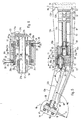
- one-sided storage of the turbine rotor 15 a can also be a two-sided storage according to Fig. 4 be provided, wherein it can be in the rolling bearing 41, which is arranged on the side facing away from the tool 6 of the turbine wheel 15, a conventional radial bearing and / or a thrust bearing.
- a radial bearing is provided which can absorb even small axial loads and sits with its inner ring on a arranged on this side of the turbine 15 bearing pin 18a and the outer ring is mounted in a bearing bore 42 of a preferably screwed into the head housing cover 43. With the covers 43 removed, the turbine rotor 15a can be removed upward from the head housing.
- the supply of the at least one treatment medium can be arranged distributed through one or more circumferentially Outlet openings 44 take place, which are arranged in the peripheral wall 14a or in the end wall 35.
- an annular channel 45 surrounding the bearing bush 23 in its tool-side end region is present in the peripheral wall 14a, which extends up to the end wall 35, wherein a plurality of media channels distributed on the circumference and preferably convergent extending from the annular channel 45 and penetrate the end wall 35.
- the media line 11 opens into the annular channel 45.
- the joint arranged between the peripheral wall 14a and the bearing bush 23 and / or the joint arranged between the end wall 35 and the bearing bush 23 can each be sealed by a ring seal, e.g. by an O-ring 46 which sits in an annular groove which is arranged in one of the two parts in a conventional manner.
- FIGS. 2 and 3 it is in accordance with both embodiments FIGS. 2 and 3 possible to arrange the one or more retaining rings 24 in a corresponding arrangement between the rolling bearing inner rings or 21b and the receiving sleeve 18, wherein at least one of the annular groove 25 corresponding groove in the outer circumferential surface of the receiving sleeve 18 is arranged and arranged at least one annular groove 26 in the inner circumferential surface of the rolling bearing inner ring 21b is.
- the invention axially and possibly also radially elastically yielding bearing in the shaft 13 for pivotally mounted therein rotatably mounted rotary member 12 is arranged, here for pivotally mounting a drive shaft longitudinal section.
- a drive motor 51 for example an electric motor, arranged in dash-dotted supplemented connector part 2 and drivingly connected by a drive shaft or a Antriebswellenzug 53 with a plurality of drive shaft sections with the receiving sleeve 18.
- the drive shaft train 53 has a plug-in coupling 52 with two plug-in coupling elements 52a, 52b which correspond to one another in a form-fitting manner, whereby a coupling and uncoupling of the plug-in coupling 52 is possible when the plug-in coupling 4 is coupled and uncoupled.
- a drive shaft portion 53a disposed in the rear end portion of the handpiece 3 extends to the apex portion of the angled shaft 13 with its forward end drivingly connected to a third drive shaft portion 53c by a second drive shaft portion 53b axially extending substantially only in the apex region front shank portion 13b extends to the receiving sleeve 18 and is drivingly connected thereto.
- a gear transmission is provided in each case.
- a gear 54 having an internal toothing meshing with a pinion 55 at the rear end of the second drive shaft portion 53b is disposed.
- the second drive shaft section 53b is offset with respect to the apex 13c of the bend or curvature to the tool 6 opposite side, wherein at the front end of the second drive shaft section 53b and the rear end of the third drive shaft section 53c each have a pinion 56, 57 substantially in one Transverse plane or are arranged overlapping each other, in the sense of front or bevel gears which mesh with each other.
- the second and third drive shaft sections 53b, 53c include an obtuse angle W1, which is open to the side facing away from the tool 6.
- the drive connection between the third drive shaft section 53 c and the receiving sleeve 18 is formed by a bevel gear with a bevel gear 58 at the front end of the third drive shaft section 53 c and bevel gear 59 on the receiving sleeve 18.
- the tooth engagement between the bevel gears 58, 59 is arranged with respect to the third drive shaft section 53 c on its side facing away from the tool 6. As a result, the receiving sleeve 18 is driven in the same direction of rotation as the first drive shaft section 53a.
- the receiving sleeve 18 is rotatably supported by two roller bearings 61, 62 in the head 14, which have a longitudinal axis of rotation 16 directed distance from each other, which is larger than the bevel gear 58, so that the latter can be arranged therebetween, including the bevel gear 59, the the side facing away from the tool 6 of the bevel gear 58 and at the same time on the tool 6 facing side of the rolling bearing 61 is disposed further away from the tool 6 than the other rolling bearing 62.
- a rolling bearing 63, 64 arranged on the end regions of this drive shaft section 53c, the outer rings are seated and supported in a longitudinal hole, not shown, of the shaft portion 13b.
- the configuration of the gear 54 as a ring gear allows a relatively large translation of the rotational speed between the first and the second drive shaft section 53a, 53b with a radially small construction.
- a double-row roller bearing 65, 66 is respectively provided in the shaft 13 in a bearing bush.
- This rolling bearing 65, 66 is sufficient in each case to store the entire drive shaft section 53a or 53b sufficiently stable.
- the first drive shaft portion 53a projects beyond the rolling bearing 65 freely projecting rearward, whereby a slight radial flexibility for coupling with the drive shaft portion of the connecting part 2 is present.
- a hinge connection 68 may be connected to a transverse pin 69, whereby the radial flexibility of the first drive shaft portion 53 a is increased.
- the gear 54 consists of a rear cylindrical or hollow cylindrical bearing portion 54 a, at the front end of a flange 54 b is arranged, which carries on its front side the ring gear 54.
- the rolling bearings 65 66 may be two, e.g. Having an axially spaced rolling bearing inner rings 21b or an axially continuous Wälzlagerinnenhülse (not shown).
- the axial distance of the rows of rolling elements can be preferably dimensioned larger than the average diameter of the WälzSystemtownrillen.
- the rolling bearing 66 is dimensioned so long, see L, that it fits between the pinions 55, 56, whereby at the same time an axial boundary for the second drive shaft section 52b is formed.
- Both roller bearings 65, 66 are preferably mounted in a common, a bearing bushing 23 forming support body 71 which sits in the apex portion adjacent the rear shaft portion 13a in the shaft 13 and by a back or forward ausmündendes receiving hole 71a mounted from the rear and to the rear is again disassembled or vice versa and axially fixed in the shaft portion 13a in a manner not shown.
- the rear roller bearing 65 is inserted into the receiving hole 71 a of the support body 71 from the rear and z. B. axially fixed by a at the rear end of the outer bearing sleeve 65a arranged flange 65b toward the front.
- the front bearing 66 is from the front into a receiving hole 72 of the support body 71 used and axially fixed or positioned in the sense described by one or two retaining rings 24.
- the flange constituting the gear 54 is supported in the receiving hole 71a between the rolling bearing 65 and the bottom of the receiving hole 71 with clearance.
- FIGS. 5 and 6 is the outer bearing sleeve 66a in its outer circumferential surface 66c of the single and double row roller bearing 66 at least one, preferably associated with an axially spaced-apart retaining rings 24, wherein in the embodiment according to Fig. 2 or 3 can be trained.
- FIGS. 5 and 6 is only the design after Fig. 2 shown. In order to avoid repetition, reference is made in this regard to the description of the exemplary embodiments FIGS. 2 and 3 Referenced.
- the rolling bearing outer ring here the common outer bearing sleeve 66a, positioned at one of its ends, here at its rear end, on a shoulder 67 in the support body 71, which may be formed by a step surface in the outer bearing sleeve 66a receiving bore.
- the at least one annular groove 26 is offset with respect to the associated annular groove 25 to the shoulder 67 facing away from the outer bearing sleeve 66a on the shoulder 67, which is made Fig. 6 can be clearly seen.
- the securing ring 24 is deformed asymmetrically with respect to its ring plane, whereby due to its elasticity it is endeavored to assume its symmetrical shape.
- the locking ring 24 generates an axial force, see arrow 68, which elastically biases the outer bearing sleeve 66a against the shoulder 67 and thus ensures their abutment against the shoulder 67.
- a further advantage of the securing or positioning device 20 is that an annular seal is formed by the securing ring 24 for sealing the joint between the inner circumferential surface 23a and the bearing journal, in particular when the securing ring 24 not only against the bottom of the annular groove 26, but also resiliently biased against the bottom of the annular groove 25.
- this handpiece 3 denotes a light-conducting rod, which extends in the vicinity of the edge of the tool side of the shank 13 in this exit window 82 directed from rear to front onto the free end of the tool 6.
- a light source 83 is coupled into the Lichtleitstab 81, wherein the light source 83 is arranged on a rotatably mounted in or on the connector part 2 carousel 84 (shown by way of suggestion), which by a driver 13 d form-fitting with the Handpiece 13 is connected so that the free rotation of the handpiece 3 in the plug / rotary coupling 4 is guaranteed in this case.
- the in Fig. 5 between the central axis of the front shaft portion 13b and the rotation axis 16 of the receiving sleeve 18 included angle W2 is more than 90 °, preferably substantially 100.
- Such a configuration is particularly favorable considering the anatomy in the mouth of a patient.
- This favorable embodiment with the angle W2 equal to about 100 ° applies not only for the operable with a motor in the connector part 2 handpiece 3 according to Fig. 5 , but also for the turbine handpiece 3 according to Fig.1 ,
- the embodiments of the invention are also particularly well suited for a handpiece that is not angularly shaped, as in Fig. 1 is shown, but which is arcuately curved in its front region, wherein the apex 13c in the center of curvature or on the tool 6 opposite end of the curvature can be arranged.
- the more than 90 ° and preferably substantially 100 ° amount angle W2 extends in the curved shape of the handpiece 3 between the central axis of the holding device 5 and a tangent plane TE, in which the in Fig. 1 dash-dotted lines indicated curved central axis 13c of the handpiece 3, the central axis 16 of the holding device 5 intersects.
- the outer ring 65 a can by one of the securing device 20 according to Fig. 6 corresponding, but twisted by 180 ° securing device directed against an unwanted displacement to the rear, which is in Fig. 5 not shown.
- the securing device 20 according to the invention can also be arranged between the inner ring 21b and the rotary part 12 in the above-described embodiments corresponding embodiments.
Landscapes
- Engineering & Computer Science (AREA)
- Health & Medical Sciences (AREA)
- General Engineering & Computer Science (AREA)
- Oral & Maxillofacial Surgery (AREA)
- Mechanical Engineering (AREA)
- Public Health (AREA)
- Animal Behavior & Ethology (AREA)
- Epidemiology (AREA)
- Veterinary Medicine (AREA)
- General Health & Medical Sciences (AREA)
- Dentistry (AREA)
- Life Sciences & Earth Sciences (AREA)
- Chemical & Material Sciences (AREA)
- Acoustics & Sound (AREA)
- Aviation & Aerospace Engineering (AREA)
- Physics & Mathematics (AREA)
- Combustion & Propulsion (AREA)
- Dental Tools And Instruments Or Auxiliary Dental Instruments (AREA)
- Massaging Devices (AREA)
- Rolling Contact Bearings (AREA)
Priority Applications (1)
| Application Number | Priority Date | Filing Date | Title |
|---|---|---|---|
| EP02797574A EP1420712B1 (de) | 2001-08-28 | 2002-08-09 | Medizinisches oder dentalmedizinisches handstück mit einem in einem wälzlager gelagerten drehteil |
Applications Claiming Priority (6)
| Application Number | Priority Date | Filing Date | Title |
|---|---|---|---|
| EP01120523 | 2001-08-28 | ||
| EP01120523A EP1208809B1 (de) | 2001-08-28 | 2001-08-28 | Medizinisches oder dentalmedizinisches Handstück mit wenigstens einem Drehteil |
| DE10208692 | 2002-02-28 | ||
| DE10208692A DE10208692A1 (de) | 2001-08-28 | 2002-02-28 | Medizinisches oder dentalmedizinisches Handstück mit einem in einem Wälzlager gelagerten Drehteil |
| EP02797574A EP1420712B1 (de) | 2001-08-28 | 2002-08-09 | Medizinisches oder dentalmedizinisches handstück mit einem in einem wälzlager gelagerten drehteil |
| PCT/EP2002/008933 WO2003020150A1 (de) | 2001-08-28 | 2002-08-09 | Medizinisches oder dentalmedizinisches handstück mit einem in einem wälzlager gelagerten drehteil |
Publications (2)
| Publication Number | Publication Date |
|---|---|
| EP1420712A1 EP1420712A1 (de) | 2004-05-26 |
| EP1420712B1 true EP1420712B1 (de) | 2008-04-09 |
Family
ID=26011044
Family Applications (1)
| Application Number | Title | Priority Date | Filing Date |
|---|---|---|---|
| EP02797574A Expired - Lifetime EP1420712B1 (de) | 2001-08-28 | 2002-08-09 | Medizinisches oder dentalmedizinisches handstück mit einem in einem wälzlager gelagerten drehteil |
Country Status (7)
| Country | Link |
|---|---|
| US (1) | US7140880B2 (enExample) |
| EP (1) | EP1420712B1 (enExample) |
| JP (1) | JP4311641B2 (enExample) |
| AT (1) | ATE391464T1 (enExample) |
| BR (1) | BR0205948A (enExample) |
| DE (2) | DE10208692A1 (enExample) |
| WO (1) | WO2003020150A1 (enExample) |
Families Citing this family (17)
| Publication number | Priority date | Publication date | Assignee | Title |
|---|---|---|---|---|
| US7215131B1 (en) | 1999-06-07 | 2007-05-08 | Formfactor, Inc. | Segmented contactor |
| DE102005016049A1 (de) | 2005-04-07 | 2006-10-12 | Kaltenbach & Voigt Gmbh | Medizinisches Handstück mit einem abgewinkelten Schaft |
| DE102005016035A1 (de) * | 2005-04-07 | 2006-10-12 | Kaltenbach & Voigt Gmbh | Turbinenrad für ein gasbetriebenes medizinisches Handstück und medizinisches Handstück mit einem Turbinenrad sowie Verfahren zum Fräsen einer Schaufel des Turbinenrads |
| US9877798B2 (en) * | 2005-04-12 | 2018-01-30 | Spring Health Products, Inc. | Electric dental handpiece |
| WO2006110670A1 (en) * | 2005-04-12 | 2006-10-19 | Spring Health Products, Inc. | Electric dental handpiece and control system |
| GB2435912B (en) * | 2006-03-06 | 2008-05-14 | Honda Motor Co Ltd | Electric motor and electric power steering apparatus |
| US8294224B2 (en) * | 2006-04-06 | 2012-10-23 | Micron Technology, Inc. | Devices and methods to improve carrier mobility |
| GB0905110D0 (en) * | 2009-03-25 | 2009-05-06 | Rolls Royce Plc | Bearing arrangement |
| AT512049B1 (de) * | 2012-01-30 | 2013-05-15 | Steger Heinrich | Bearbeitungsvorrichtung für ein zahntechnisches werkstück |
| DE102012205275A1 (de) * | 2012-03-30 | 2013-10-02 | Sirona Dental Systems Gmbh | Zahnärztliches Handstück mit Wälzlager |
| JP6287323B2 (ja) * | 2013-09-24 | 2018-03-07 | 日本精工株式会社 | 歯科エアタービン用軸受ユニット及び歯科エアタービン |
| EP3108846B1 (en) * | 2014-02-19 | 2021-06-23 | J. Morita Manufacturing Corporation | Medical instrument element |
| US20160081766A1 (en) * | 2014-09-23 | 2016-03-24 | Young Innovations, Inc. | Corded Dental Handpiece |
| CN105736583A (zh) * | 2016-04-21 | 2016-07-06 | 浙江天马轴承有限公司 | 一种双列角接触球轴承及其安装结构 |
| GB2563617B (en) | 2017-06-20 | 2020-04-08 | Dyson Technology Ltd | An electric machine |
| US20210330425A1 (en) * | 2020-04-27 | 2021-10-28 | Innovative Bioceramix Inc. | Endodontic handpiece systems and methods |
| US20240299130A1 (en) * | 2023-03-06 | 2024-09-12 | King Faisal University | Endodontic tool with a rotating tip |
Citations (1)
| Publication number | Priority date | Publication date | Assignee | Title |
|---|---|---|---|---|
| WO2002022039A1 (en) * | 2000-09-14 | 2002-03-21 | Dentsply International Inc. | Improved bearing for dental handpiece |
Family Cites Families (10)
| Publication number | Priority date | Publication date | Assignee | Title |
|---|---|---|---|---|
| FR1316974A (fr) * | 1961-03-07 | 1963-02-01 | Pièce à main à usage dentaire | |
| US4249896A (en) * | 1978-09-29 | 1981-02-10 | Syntex (U.S.A.) Inc. | Compliantly mountable turbine cartridge assembly for gas-driven dental handpiece |
| US4231739A (en) * | 1979-04-11 | 1980-11-04 | Professional Mfg. Corp. | Unitary cartridge type turbine assembly |
| JPH0613039B2 (ja) * | 1987-07-22 | 1994-02-23 | 而至歯科工業株式会社 | チヤツク無し歯科用ハンドピ−ス |
| US5507642A (en) * | 1993-06-21 | 1996-04-16 | Siemens Aktiengesellschaft | Dental turbine drive |
| US5779474A (en) * | 1994-06-09 | 1998-07-14 | Den-Tal-Ez, Inc. | Sudden stop mechanism and air-gap seal for dental handpiece |
| DE4423222A1 (de) * | 1994-07-01 | 1996-01-04 | Kaltenbach & Voigt | Ärztliches oder zahnärztliches Behandlungsinstrument |
| DE9412908U1 (de) * | 1994-08-10 | 1995-12-07 | Sirona Dental Systems GmbH, 64625 Bensheim | Zahnärztliche Antriebseinheit mit einer in Wälzlagern gelagerten Welle |
| DE19833249A1 (de) * | 1998-07-23 | 2000-01-27 | Kaltenbach & Voigt | Turbinen-Handstück, insbesondere für medizinische oder dentalmedizinische Zwecke |
| IL133037A0 (en) | 1999-07-01 | 2001-03-19 | Medivice Systems Ltd | Improved dental drill head |
-
2002
- 2002-02-28 DE DE10208692A patent/DE10208692A1/de not_active Withdrawn
- 2002-08-09 EP EP02797574A patent/EP1420712B1/de not_active Expired - Lifetime
- 2002-08-09 JP JP2003524464A patent/JP4311641B2/ja not_active Expired - Fee Related
- 2002-08-09 DE DE50212074T patent/DE50212074D1/de not_active Expired - Lifetime
- 2002-08-09 AT AT02797574T patent/ATE391464T1/de active
- 2002-08-09 WO PCT/EP2002/008933 patent/WO2003020150A1/de not_active Ceased
- 2002-08-09 BR BR0205948-7A patent/BR0205948A/pt not_active IP Right Cessation
-
2003
- 2003-04-28 US US10/426,355 patent/US7140880B2/en not_active Expired - Fee Related
Patent Citations (1)
| Publication number | Priority date | Publication date | Assignee | Title |
|---|---|---|---|---|
| WO2002022039A1 (en) * | 2000-09-14 | 2002-03-21 | Dentsply International Inc. | Improved bearing for dental handpiece |
Also Published As
| Publication number | Publication date |
|---|---|
| BR0205948A (pt) | 2003-12-23 |
| US20030190583A1 (en) | 2003-10-09 |
| DE50212074D1 (de) | 2008-05-21 |
| DE10208692A1 (de) | 2003-03-20 |
| EP1420712A1 (de) | 2004-05-26 |
| ATE391464T1 (de) | 2008-04-15 |
| JP4311641B2 (ja) | 2009-08-12 |
| JP2005501598A (ja) | 2005-01-20 |
| US7140880B2 (en) | 2006-11-28 |
| WO2003020150A1 (de) | 2003-03-13 |
Similar Documents
| Publication | Publication Date | Title |
|---|---|---|
| EP1420712B1 (de) | Medizinisches oder dentalmedizinisches handstück mit einem in einem wälzlager gelagerten drehteil | |
| EP1816346B1 (de) | Stellantrieb zur Einstellung des Anstellwinkels eines Rotorblatts | |
| EP0012872B1 (de) | Zahnärztliche Handstückanordnung | |
| EP1429054A2 (de) | Planetengetriebe | |
| DE4207839A1 (de) | Nabenbefestigung | |
| WO2009013074A2 (de) | Wellgenerator für ein wellgetriebe | |
| EP1779803B1 (de) | Wälzlager, Medizinisches oder dentalmedizinisches Handstück mit demselben | |
| EP2712413A2 (de) | Anschlussvorrichtung zum anschliessen einer fluidleitung | |
| DE69803477T2 (de) | Trommelmotor | |
| EP2161478B1 (de) | Zahnradanordnung | |
| AT518787B1 (de) | Zahnradanordnung | |
| EP1378207B1 (de) | Medizinisches oder dentalmedizinisches Handstück mit einer Drucktaste zum Lösen eines Werkzeugs | |
| DE102017127874A1 (de) | Planetengetriebe und Planetenrad für ein Planetengetriebe | |
| EP0949419A1 (de) | Innenzahnradmaschine | |
| DE2742442C3 (de) | Elastische Kupplung | |
| EP2545293B1 (de) | Gelenklager und verfahren zur herstellung eines gelenklagers | |
| EP2025300B1 (de) | Medizinisches oder dentalmedizinisches Handstück | |
| CH672415A5 (enExample) | ||
| AT503722B1 (de) | Medizinisches, insbesondere dentalmedizinisches, handstück und dazugehöriges werkzeug | |
| DE3036939A1 (de) | Zahnaerztliche handstueckanordnung | |
| EP1709933B1 (de) | Medizinisches Handstück mit einem abgewinkelten Schaft | |
| EP3276127B1 (de) | Zahnradfluidmaschine | |
| DE1541192C (de) | Zahnärztliches Turbmenhandstuck | |
| DE4323503A1 (de) | Kardandoppelgelenk | |
| EP3887689A1 (de) | Kettenglied und kette und kettenrad |
Legal Events
| Date | Code | Title | Description |
|---|---|---|---|
| PUAI | Public reference made under article 153(3) epc to a published international application that has entered the european phase |
Free format text: ORIGINAL CODE: 0009012 |
|
| 17P | Request for examination filed |
Effective date: 20030424 |
|
| AK | Designated contracting states |
Kind code of ref document: A1 Designated state(s): AT BE BG CH CY CZ DE DK EE ES FI FR GB GR IE IT LI LU MC NL PT SE SK TR |
|
| 17Q | First examination report despatched |
Effective date: 20060724 |
|
| 17Q | First examination report despatched |
Effective date: 20060724 |
|
| GRAP | Despatch of communication of intention to grant a patent |
Free format text: ORIGINAL CODE: EPIDOSNIGR1 |
|
| GRAS | Grant fee paid |
Free format text: ORIGINAL CODE: EPIDOSNIGR3 |
|
| GRAA | (expected) grant |
Free format text: ORIGINAL CODE: 0009210 |
|
| RAP1 | Party data changed (applicant data changed or rights of an application transferred) |
Owner name: KALTENBACH & VOIGT GMBH |
|
| AK | Designated contracting states |
Kind code of ref document: B1 Designated state(s): AT CH DE FR IT LI |
|
| REG | Reference to a national code |
Ref country code: CH Ref legal event code: EP |
|
| REF | Corresponds to: |
Ref document number: 50212074 Country of ref document: DE Date of ref document: 20080521 Kind code of ref document: P |
|
| REG | Reference to a national code |
Ref country code: CH Ref legal event code: NV Representative=s name: BOHEST AG |
|
| ET | Fr: translation filed | ||
| PLBE | No opposition filed within time limit |
Free format text: ORIGINAL CODE: 0009261 |
|
| STAA | Information on the status of an ep patent application or granted ep patent |
Free format text: STATUS: NO OPPOSITION FILED WITHIN TIME LIMIT |
|
| 26N | No opposition filed |
Effective date: 20090112 |
|
| PGFP | Annual fee paid to national office [announced via postgrant information from national office to epo] |
Ref country code: CH Payment date: 20110929 Year of fee payment: 10 |
|
| PGFP | Annual fee paid to national office [announced via postgrant information from national office to epo] |
Ref country code: FR Payment date: 20120903 Year of fee payment: 11 Ref country code: IT Payment date: 20120827 Year of fee payment: 11 |
|
| PGFP | Annual fee paid to national office [announced via postgrant information from national office to epo] |
Ref country code: DE Payment date: 20121001 Year of fee payment: 11 |
|
| PGFP | Annual fee paid to national office [announced via postgrant information from national office to epo] |
Ref country code: AT Payment date: 20120830 Year of fee payment: 11 |
|
| REG | Reference to a national code |
Ref country code: CH Ref legal event code: PL |
|
| REG | Reference to a national code |
Ref country code: AT Ref legal event code: MM01 Ref document number: 391464 Country of ref document: AT Kind code of ref document: T Effective date: 20130809 |
|
| PG25 | Lapsed in a contracting state [announced via postgrant information from national office to epo] |
Ref country code: LI Free format text: LAPSE BECAUSE OF NON-PAYMENT OF DUE FEES Effective date: 20130831 Ref country code: DE Free format text: LAPSE BECAUSE OF NON-PAYMENT OF DUE FEES Effective date: 20140301 Ref country code: CH Free format text: LAPSE BECAUSE OF NON-PAYMENT OF DUE FEES Effective date: 20130831 |
|
| REG | Reference to a national code |
Ref country code: DE Ref legal event code: R119 Ref document number: 50212074 Country of ref document: DE Effective date: 20140301 |
|
| REG | Reference to a national code |
Ref country code: FR Ref legal event code: ST Effective date: 20140430 |
|
| PG25 | Lapsed in a contracting state [announced via postgrant information from national office to epo] |
Ref country code: IT Free format text: LAPSE BECAUSE OF NON-PAYMENT OF DUE FEES Effective date: 20130809 Ref country code: AT Free format text: LAPSE BECAUSE OF NON-PAYMENT OF DUE FEES Effective date: 20130809 |
|
| PG25 | Lapsed in a contracting state [announced via postgrant information from national office to epo] |
Ref country code: FR Free format text: LAPSE BECAUSE OF NON-PAYMENT OF DUE FEES Effective date: 20130902 |