EP1420267B1 - Radarsensor und Radarantenne für ein Überwachen der Umgebung eines Kraftfahrzeugs - Google Patents
Radarsensor und Radarantenne für ein Überwachen der Umgebung eines Kraftfahrzeugs Download PDFInfo
- Publication number
- EP1420267B1 EP1420267B1 EP04003251A EP04003251A EP1420267B1 EP 1420267 B1 EP1420267 B1 EP 1420267B1 EP 04003251 A EP04003251 A EP 04003251A EP 04003251 A EP04003251 A EP 04003251A EP 1420267 B1 EP1420267 B1 EP 1420267B1
- Authority
- EP
- European Patent Office
- Prior art keywords
- radar
- antenna
- radar antenna
- lens
- rows
- Prior art date
- Legal status (The legal status is an assumption and is not a legal conclusion. Google has not performed a legal analysis and makes no representation as to the accuracy of the status listed.)
- Expired - Lifetime
Links
Images



Classifications
-
- H—ELECTRICITY
- H01—ELECTRIC ELEMENTS
- H01Q—ANTENNAS, i.e. RADIO AERIALS
- H01Q21/00—Antenna arrays or systems
- H01Q21/06—Arrays of individually energised antenna units similarly polarised and spaced apart
- H01Q21/061—Two dimensional planar arrays
- H01Q21/065—Patch antenna array
-
- G—PHYSICS
- G01—MEASURING; TESTING
- G01S—RADIO DIRECTION-FINDING; RADIO NAVIGATION; DETERMINING DISTANCE OR VELOCITY BY USE OF RADIO WAVES; LOCATING OR PRESENCE-DETECTING BY USE OF THE REFLECTION OR RERADIATION OF RADIO WAVES; ANALOGOUS ARRANGEMENTS USING OTHER WAVES
- G01S7/00—Details of systems according to groups G01S13/00, G01S15/00, G01S17/00
- G01S7/02—Details of systems according to groups G01S13/00, G01S15/00, G01S17/00 of systems according to group G01S13/00
- G01S7/03—Details of HF subsystems specially adapted therefor, e.g. common to transmitter and receiver
- G01S7/032—Constructional details for solid-state radar subsystems
-
- H—ELECTRICITY
- H01—ELECTRIC ELEMENTS
- H01Q—ANTENNAS, i.e. RADIO AERIALS
- H01Q1/00—Details of, or arrangements associated with, antennas
- H01Q1/27—Adaptation for use in or on movable bodies
- H01Q1/32—Adaptation for use in or on road or rail vehicles
- H01Q1/3208—Adaptation for use in or on road or rail vehicles characterised by the application wherein the antenna is used
- H01Q1/3233—Adaptation for use in or on road or rail vehicles characterised by the application wherein the antenna is used particular used as part of a sensor or in a security system, e.g. for automotive radar, navigation systems
-
- H—ELECTRICITY
- H01—ELECTRIC ELEMENTS
- H01Q—ANTENNAS, i.e. RADIO AERIALS
- H01Q1/00—Details of, or arrangements associated with, antennas
- H01Q1/27—Adaptation for use in or on movable bodies
- H01Q1/32—Adaptation for use in or on road or rail vehicles
- H01Q1/325—Adaptation for use in or on road or rail vehicles characterised by the location of the antenna on the vehicle
- H01Q1/3283—Adaptation for use in or on road or rail vehicles characterised by the location of the antenna on the vehicle side-mounted antennas, e.g. bumper-mounted, door-mounted
-
- H—ELECTRICITY
- H01—ELECTRIC ELEMENTS
- H01Q—ANTENNAS, i.e. RADIO AERIALS
- H01Q23/00—Antennas with active circuits or circuit elements integrated within them or attached to them
-
- H—ELECTRICITY
- H01—ELECTRIC ELEMENTS
- H01Q—ANTENNAS, i.e. RADIO AERIALS
- H01Q25/00—Antennas or antenna systems providing at least two radiating patterns
- H01Q25/002—Antennas or antenna systems providing at least two radiating patterns providing at least two patterns of different beamwidth; Variable beamwidth antennas
-
- H—ELECTRICITY
- H01—ELECTRIC ELEMENTS
- H01Q—ANTENNAS, i.e. RADIO AERIALS
- H01Q25/00—Antennas or antenna systems providing at least two radiating patterns
- H01Q25/007—Antennas or antenna systems providing at least two radiating patterns using two or more primary active elements in the focal region of a focusing device
- H01Q25/008—Antennas or antenna systems providing at least two radiating patterns using two or more primary active elements in the focal region of a focusing device lens fed multibeam arrays
-
- G—PHYSICS
- G01—MEASURING; TESTING
- G01S—RADIO DIRECTION-FINDING; RADIO NAVIGATION; DETERMINING DISTANCE OR VELOCITY BY USE OF RADIO WAVES; LOCATING OR PRESENCE-DETECTING BY USE OF THE REFLECTION OR RERADIATION OF RADIO WAVES; ANALOGOUS ARRANGEMENTS USING OTHER WAVES
- G01S13/00—Systems using the reflection or reradiation of radio waves, e.g. radar systems; Analogous systems using reflection or reradiation of waves whose nature or wavelength is irrelevant or unspecified
- G01S13/88—Radar or analogous systems specially adapted for specific applications
- G01S13/93—Radar or analogous systems specially adapted for specific applications for anti-collision purposes
- G01S13/931—Radar or analogous systems specially adapted for specific applications for anti-collision purposes of land vehicles
-
- G—PHYSICS
- G01—MEASURING; TESTING
- G01S—RADIO DIRECTION-FINDING; RADIO NAVIGATION; DETERMINING DISTANCE OR VELOCITY BY USE OF RADIO WAVES; LOCATING OR PRESENCE-DETECTING BY USE OF THE REFLECTION OR RERADIATION OF RADIO WAVES; ANALOGOUS ARRANGEMENTS USING OTHER WAVES
- G01S13/00—Systems using the reflection or reradiation of radio waves, e.g. radar systems; Analogous systems using reflection or reradiation of waves whose nature or wavelength is irrelevant or unspecified
- G01S13/88—Radar or analogous systems specially adapted for specific applications
- G01S13/93—Radar or analogous systems specially adapted for specific applications for anti-collision purposes
- G01S13/931—Radar or analogous systems specially adapted for specific applications for anti-collision purposes of land vehicles
- G01S2013/9325—Radar or analogous systems specially adapted for specific applications for anti-collision purposes of land vehicles for inter-vehicle distance regulation, e.g. navigating in platoons
-
- G—PHYSICS
- G01—MEASURING; TESTING
- G01S—RADIO DIRECTION-FINDING; RADIO NAVIGATION; DETERMINING DISTANCE OR VELOCITY BY USE OF RADIO WAVES; LOCATING OR PRESENCE-DETECTING BY USE OF THE REFLECTION OR RERADIATION OF RADIO WAVES; ANALOGOUS ARRANGEMENTS USING OTHER WAVES
- G01S13/00—Systems using the reflection or reradiation of radio waves, e.g. radar systems; Analogous systems using reflection or reradiation of waves whose nature or wavelength is irrelevant or unspecified
- G01S13/88—Radar or analogous systems specially adapted for specific applications
- G01S13/93—Radar or analogous systems specially adapted for specific applications for anti-collision purposes
- G01S13/931—Radar or analogous systems specially adapted for specific applications for anti-collision purposes of land vehicles
- G01S2013/9327—Sensor installation details
- G01S2013/93271—Sensor installation details in the front of the vehicles
-
- G—PHYSICS
- G01—MEASURING; TESTING
- G01S—RADIO DIRECTION-FINDING; RADIO NAVIGATION; DETERMINING DISTANCE OR VELOCITY BY USE OF RADIO WAVES; LOCATING OR PRESENCE-DETECTING BY USE OF THE REFLECTION OR RERADIATION OF RADIO WAVES; ANALOGOUS ARRANGEMENTS USING OTHER WAVES
- G01S13/00—Systems using the reflection or reradiation of radio waves, e.g. radar systems; Analogous systems using reflection or reradiation of waves whose nature or wavelength is irrelevant or unspecified
- G01S13/88—Radar or analogous systems specially adapted for specific applications
- G01S13/93—Radar or analogous systems specially adapted for specific applications for anti-collision purposes
- G01S13/931—Radar or analogous systems specially adapted for specific applications for anti-collision purposes of land vehicles
- G01S2013/9327—Sensor installation details
- G01S2013/93275—Sensor installation details in the bumper area
Definitions
- the present invention relates to a radar antenna, which is particularly suitable for monitoring the environment of a motor vehicle, according to the preamble of claim 1.
- Such radar antennas are needed for different comfort and safety-relevant driver assistance systems. They use forward-facing sensors in the direction of travel to gather information about traffic and obstacles on the road. This information is used by the associated driver assistance system to perform automatic ranging or automatic emergency braking, or to use for adaptive cruise control, collision avoidance, and future autonomous vehicle driving applications.
- a radar sensor which has a control circuit and a radar antenna, wherein the control circuit is designed as a transmitting and receiving module and wherein the radar antenna is connected to at least one supply line to the control circuit.
- a part of the control circuit is designed as an MMIC (monolithic millimeter-wave integrated circuit).
- the radar antenna is in the form of a printed circuit and has a red lens and a group antenna.
- the red-lens lens has a lenticular parallel plate line, at least two lead terminals, a plurality of docking terminals, and delay lines. Furthermore, the array antenna is composed of a plurality of individual antennas, which are connected in series to at least two rows. Each of these series of individual antennas is connected to a delay line which transmits the high-frequency signal delivered by the parallel plate line to the associated coupling terminal to the row of individual antennas.
- documents WO 99 27 385 A, US-A-5 929 802 and US-A-5 675 345 show a radar antenna according to the preamble of claim 1.
- the entire radar antenna occupies a large volume at right angles to each other due to the arrangement of the red lens and the array antenna.
- the requirements for the dimensions of a radar antenna can be satisfactorily fulfilled only to order it, for example, in the bumper of a motor vehicle.
- the invention is therefore based on the technical problem of designing and developing the radar antenna known from the prior art in such a way that the disadvantages of the prior art described above are eliminated.
- a radar antenna having a red lens having a parallelepiped-shaped parallel plate line, at least two lead terminals, a plurality of coupling terminals and delay lines, and a group antenna having a plurality of individual antennas connected to at least two rows are each connected in series, wherein the rotor lens and the array antenna are arranged substantially parallel and spaced from each other.
- a space-saving arrangement of red lens and array antenna is achieved in an advantageous manner, so that a planar design of the radar antenna and beyond the radar sensor is possible, which greatly simplifies a deployment in a motor vehicle.
- a planar radar antenna in the bumper of a motor vehicle. This includes the arrangement of the red lens and the array antenna on a substrate side by side with a.
- the red lens and the array antenna are formed on two different substrates, wherein the two substrates are connected to each other with their side facing away from the red lens or the array antenna and wherein a common metallization layer is arranged between the two substrates.
- This preferably serves as a common ground for the red lens and the array antenna.
- coupling slots are formed in the metallization layer, which couple the antenna terminals of the rows of individual antennas of the array antenna with the connection points of the delay lines electromagnetically.
- connection points of the rows of individual antennas are arranged substantially in the middle of the rows, whereby a symmetrical amplitude distribution is achieved on the individual antennas within a row of individual antennas.
- the directional characteristic of the radar antenna is further improved.
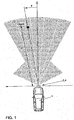
- a motor vehicle 1 which has at its front end in the region of the bumper a radar sensor 2 with a radar antenna 4 which has an azimuthal directional characteristic which has a separate sensitivity for different angular sections ⁇ .
- objects can be detected with angular resolution to characterize the environment of the motor vehicle 1.
- the determination of the distance R and the relative velocity v is also possible, so that vehicles or objects traveling in front can be detected on the road, in order thus to influence the driving behavior of the motor vehicle 1.
- Fig. 2 shows a block diagram of the general structure of the entire radar sensor and a downstream evaluation system.
- the radar antenna 4 In the front end 6, the radar antenna 4, a control circuit 8 and an analog / digital converter 10 are arranged.
- the control circuit 8 is designed as a transmitting and / or receiving module and has at least one MMIC device.
- the radar antenna 4 is connected to at least one feed line 12 to the control circuit 8.
- the analog / digital converter 10 is connected to a trained as an electronic control unit first controller 14, which in turn is connected to a second control device, which is formed, for example, as a vehicle-internal evaluation computer.
- a second control device which is formed, for example, as a vehicle-internal evaluation computer.
- the electronic control unit of the first control unit 14 is not only used to evaluate the signals received by the radar antenna 4, but also the control of the radar antenna 4 for emitting radar signals. Therefore, in the example shown in Fig. 2, the radar antenna 4 is formed monostatically, so serves both as a transmitting antenna and as a receiving antenna.
- a bistatic embodiment of the radar sensor with two different radar antennas.
- a central unit of the radar sensor 2 is the control circuit 8, which is designed as a transmitting and receiving module. On the one hand, it has the task of providing the frequency-modulated radar signal with sufficient power of the radar antenna 4. On the other hand, the control circuit 8 mixes the signal received by the radar antenna 4 with a local oscillator signal, so that a signal is produced in the baseband.
- the control circuit 8 as a transmitting and receiving module thus represents the interface between the signal processing and the radar antenna 4 and the radar antennas 4.
- both the radar antenna 4 and the control circuit 8 are constructed in planar technology. As already mentioned, the control circuit 8 has MMIC components for this purpose.
- FIG. 3 schematically shows a first example of a radar sensor.
- the control circuit 8 has two MMIC components 18 and 20, which realize, inter alia, the functions of the ozillator and an I / O mixer.
- the radar sensor has a planar radar antenna 4, which-as will be explained in more detail below-has a red-lens lens 22 and an array antenna 24, which are applied to a substrate 26.
- a line carrier 28 is provided, are formed on the lines 30, which serve for the transmission of high-frequency signals between the MMIC components 18 and 20 of the control circuit 8 and the leads 12 of the radar antenna 4.
- the line carrier 28 between the control circuit 8, so the MMIC components 18 and 20, and the radar antenna 4 is arranged.
- lines 30 extend substantially in a plane parallel to the tracks of the control circuit 8 and the leads 12 of the radar antenna 4. This ensures that the connections between the lines 30 and the leads 12 of the radar antenna 4 and the MMIC components 18 and 20 can be formed very short. As a result, in particular the losses in the transmission of high-frequency signals are kept to a minimum.
- the lines 30 for the transmission of high-frequency signals are designed as microstrip lines on the line carrier 28.
- the line carrier 28 is, for example, made of GaAs or Al 2 O 3 .
- microstrip lines based on GaAs is carried out in a plurality of manufacturing steps.
- a wafer is divided into samples which have meaningful sizes for the production of the conductor carriers. This is done by scribing a predetermined breaking point with a diamond and breaking the wafer over an edge. Subsequently, the wafer piece is thinned to a required thickness by a wet chemical etching polishing method. In addition to the etching attack of the etching solution, such as bromomethane solution, the reduction in thickness is also supported by a purely mechanical abrasion on a polishing cloth. Thereafter, the wafer pieces are cleaned to ensure good adhesion of the metallization on the GaAs. For this purpose, both the self-oxide and organic contaminants are removed from the semiconductor surface.
- the metallization occurs to prevent re-formation of native oxide on the sample surface.
- the metallization consists of a 10nm thick primer made of chrome, a 100nm thick vapor deposited gold layer and finally 3 ⁇ m electroplated gold. Since a microstrip line has its ground potential on the substrate bottom, both sides of the wafer piece serving as a substrate must be metallized.
- the sample consisting of the substrate and metallization is glued to a glass slide with a photoresist. With this step, on the one hand, the handling of the sensitive GaAs facilitates and secondly, during the etching, the metallization on the back of the sample is protected.
- the photoresist is dissolved in acetone and the sample is thus released from its support again.
- they are subjected to a paint ashing step, so that in particular remain on the tracks no paint residues, which lead to a deteriorated adhesion of a bonding wire.
- the samples are cut with high precision into the GaAs conductor carriers.
- a circuit carrier 32 which provides a stable basis for the assembly of the sensitive MMIC devices 18 and 20 and for the line carrier 28. These are connected to the circuit substrate 32 with an adhesive.
- the radar antenna 4 is partially also connected to the circuit carrier 32.
- the material of the circuit substrate 32 is adapted to the thermal expansion behavior of the substrates of the MMIC components 18 and 20, the conductor support 28 and the radar antenna 4, which occur in particular when used with a motor vehicle large temperature differences ,
- Al 2 O 3 has been selected in the present exemplary embodiment.
- 32 lines for power supply and for connection to the first control unit 14 are formed directly on the substrate of the circuit substrate.
- the circuit carrier 32 also has a further function.
- the MMIC devices 18 and 20, the line carrier 28 and partially the radar antenna 4 are connected to the circuit carrier 32.
- the line carrier 28 is not connected by means of a wire bond 31, but by means of an electromagnetic field coupling 34, as will be explained in more detail with reference to FIG. 5.
- the substrate 36 on which the radar antenna 4 is at least partly formed, namely in the form of the red-lens 22, has on the side shown in FIG. 5 at the top a mass metallization which has a recess 40 and therein a coplanar line 42.
- a mass metallization 44 On the surface of the circuit substrate 32 shown in Fig. 5 above a mass metallization 44, a recess 46 and a coplanar line 48 are formed symmetrically to the configuration of the surface of the substrate 36.
- the circuit substrate 32 is reversed with the surface shown in Fig. 5 upside down on the substrate 36 for abutment, whereby the two Koplanar effeten 42 and 48 at least partially overlapping each other. This results in an electrical contact between the two coplanar lines 42 and 48.
- the coplanar lines 42 are also shown in Fig. 6 in their arrangement relative to the leads 12.
- a supply line 12 is shown in Fig. 5 with dashed lines, which is designed as a microstrip line.
- the arrow 52 points in the direction of the radar antenna 4, in particular the red-lens 22.
- the line carrier 28 which has a line 30 in the form of a microstrip line with the surface 30 facing away from the surface mounted on the circuit substrate 32, as shown by the arrow 54.
- the arrow 56 points in the direction of the control circuit 8, with which the line 30 is connected.
- Both the feed line 12 and the line 30 are not electrically conductively connected to the coplanar lines 42 and 48, respectively, but they are each spaced from the coplanar lines 42 and 48 by the substrates 36 and 32, respectively.
- the lead 30 is electromagnetically coupled to the lead 12 via a series connection of two microstrip coplanar junctions.
- the first junction connects the line carrier 28 to the circuit carrier 32 and the second transition ensures the coupling of the Rotman lens 22 with the circuit substrate 32.
- the connection of the two Koplanartechnischen 42 and 48 is carried out galvanically by a flip-chip assembly.
- the above-described modular design of the radar sensor is simplified by the flip-chip mounting, since without major adaptation problems different MMIC components of various control circuits can be connected to the circuit substrate 32 and the radar antenna 4.
- the construction described above saves space.
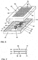
- FIG. 6 shows an exemplary embodiment of a radar antenna 4 according to the invention in an exploded view.
- the red-lens lens 22 has a parallel plate line 56, lead terminals 58, docking terminals 60, and delay lines 62.
- the array antenna 24 has individual antennas 64 connected in series 70 in series.
- the rows 70 of individual antennas differ from those of the first embodiment in that, as will be described in detail below, the coupling of the electromagnetic signals takes place substantially in the middle of the rows 70.
- the red-lens lens 22 and the array antenna 24 are now arranged parallel to one another and at a distance from one another. Therefore, red lens 22 and array antenna 24 are at least partially overlapping one another.
- the red-lens lens 22 is formed on a first substrate 72 and the array antenna on a second substrate 74.
- the two substrates 72 and 74, with their sides facing away from the red-lens lens 22 or the array antenna 24, are connected to one another by means of a common metallization layer 76.
- the metallization layer 76 serves as common ground potential.
- the two-layer structure of the radar antenna 4 is also shown in Fig. 4 and in Fig. 7.
- coupling slots 78 are formed in the metallization layer 76, which couple the connection points 80 of the rows 70 of the individual antennas 64 electromagnetically with the connection points 82 of the delay lines 62.
- the electromagnetic field is transmitted from the pads 82 through the substrate 22, through the coupling slots 78, and through the substrate 74 to the pads 80 of the array antenna 24.
- the metallization layer 76 is formed substantially over the entire surface, a good shielding of the red lens 22 is achieved by the array antenna 24 in an advantageous manner.
- a coupling slot 78 and two connection points 80 and 82 is also shown in Fig. 7. Since the coupling slot 78 specifies only a limited spatial area for the electromagnetic coupling of the two connection points 80 and 82, on the one hand a precise defined excitation of the rows 70 takes place and on the other hand a good shielding in the areas outside the coupling slots 78 is ensured.
- the control of the array antenna 24 has been described as a transmitting antenna, wherein the electromagnetic signals from the red lens 22 on the array antenna 24 is carried out.
- the array antenna 24 As a receiving antenna, the signal propagation takes place in the opposite way.
- FIGS. 8 to 10 show a more detailed configuration of the individual antennas and of the rows 70 of individual antennas 64 in detail.
- Fig. 8 shows a single antenna 64 with a feed line 84, which is designed as a microstrip line, and with a radiation surface 86, which is also called patch.
- the length of the radiation surface 86 is predetermined by the frequency of the high-frequency signal and corresponds essentially to half the wavelength of the radiation in the substrate.
- the width (b) and the relative position of the feed point (x) are selectable within limits, with both parameters being matched to one another in order to ensure good input matching.
- the edge of the radiation surface 86 labeled y is also referred to as the nonradiative side, and the two edges labeled b are referred to as the radiating sides of the radiation surface 86.
- the two parameters width (b) and length (y) can be varied within limits, as a result of which the size of the power coupled out of the row 70 for the respective individual antenna 64 and, moreover, the amplitude distribution within the row 70 can be set.
- a feed network in the form of a three-port series circuit is constructed, as shown in FIG. 9.
- a three-port is composed of two ⁇ / 4 transformers and a single antenna branch. Assuming that all individual antennas 64 work in phase, the decoupling points must therefore be electrically 360 ° apart. The connecting piece between two three-tone converters must therefore realize an electrical phase rotation of 180 °.
- the single three gates are further designed such that along the row 70, a defined fraction of the power P is a coupled in the feed strand into the supply line of the single antenna 64 depending on the desired amplitude of occupancy of the individual antennas 64th
- Z 2 is the impedance level of the feed line 84 of the single antenna 64, while Z 0 is to be referred to as the feed line impedance level.
- these can also be arranged or strung in series within the strand. The amplitude of the respective decoupled signals is then controlled across the width of the radiation surfaces.
- connection points 80 are arranged substantially in the middle of the rows 70, wherein, as shown in FIG. 10, a subdivision into ⁇ / 2 and ⁇ is made in order to have a same phase with electromagnetic waves propagating along the rows 70 in two different directions to ensure the left and right of the connection point 80 individual antennas 64.
- the substrates of the red-lens 22 and the array antenna 24 are made of a ceramic-filled composite of polytetrafluoroethylene (PTFE).
- PTFE polytetrafluoroethylene
- the size of the red lens 22 can be reduced with use of a high dielectric constant regardless of the dimensions given by the outer shape of the array antenna 24.
Landscapes
- Engineering & Computer Science (AREA)
- Remote Sensing (AREA)
- Radar, Positioning & Navigation (AREA)
- Computer Security & Cryptography (AREA)
- Computer Networks & Wireless Communication (AREA)
- Physics & Mathematics (AREA)
- General Physics & Mathematics (AREA)
- Radar Systems Or Details Thereof (AREA)
- Variable-Direction Aerials And Aerial Arrays (AREA)
- Aerials With Secondary Devices (AREA)
Description
- Die vorliegende Erfindung betrifft eine Radarantenne, die insbesondere für ein Überwachen der Umgebung eines Kraftfahrzeuges geeignet ist, gemäß dem Oberbegriff des Anspruchs 1.
- Derartige Radarantennen werden für unterschiedliche Komfort- und sicherheitsrelevante Fahrerassistenz-Systeme benötigt. Sie verwenden in Fahrtrichtung nach vorne ausgerichtete Sensoren, um Informationen über den Verkehr und Hindernisse auf der Straße zu sammeln. Diese Informationen werden von dem zugeordneten Fahrerassistenz-System verwendet, um eine automatische Distanzregelung oder eine automatische Notbremsfunktion durchzuführen oder für Anwendungen aus dem Bereich der adaptiven Fahrtregelung, der Kollisionsverhinderung und für das zukünftige autonome Fahren von Fahrzeugen zu verwenden.
- Aus der IEEE Transactions on Mircowave Theory and Techniques, VOL. 45, NO. 12 Dezember 1997, "Milimeter-Wave Radar Sensor for Automotive Intelligent Cruise Control (ICC)", M. E. Russell et al. ist ein Radarsensor bekannt, der eine Steuerschaltung und eine Radarantenne aufweist, wobei die Steuerschaltung als Sende- und Empfangsmodul ausgebildet ist und wobei die Radarantenne mit mindestens einer Zuleitung mit der Steuerschaltung verbunden ist. Ein Teil der Steuerschaltung ist dabei als MMIC (monolithic millimeterwave integrated circuit) ausgebildet. Darüber hinaus ist die Radarantenne in Form eines gedruckten Schaltkreises ausgebildet und weist eine Rotmanlinse und eine Gruppenantenne auf. Die Rotmanlinse weist eine linsenförmige Parallelplattenleitung, mindestens zwei Zuleitungsanschlüsse, eine Mehrzahl von Ankopplungsanschlüssen und Verzögerungsleitungen auf. Weiterhin ist die Gruppenantenne aus einer Mehrzahl von Einzelantennen aufgebaut, die zu mindestens zwei Reihen in Serie geschaltet sind. Jede dieser Reihe von Einzelantennen ist mit einer Verzögerungsleitung verbunden, die das von der Parallelplattenleitung an den zugeordneten Ankopplungsanschluß abgegebene hochfrequente Signal auf die Reihe von Einzelantennen überträgt.
- Ferner zeigen die Druckschriften WO 99 27 385 A, US-A-5 929 802 und US-A-5 675 345 eine Radarantenne nach dem Oberbegriff des Anspruchs 1.
- Bei der oben beschriebenen, aus dem Stand der Technik bekannten Radarantenne besteht ein Problem darin, daß die gesamte Radarantenne aufgrund der Anordnung der Rotmanlinse und der Gruppenantenne im rechten Winkel zueinander ein großes Volumen einnimmt. Somit können nur ungenügend die Anforderungen an die Abmessungen einer Radarantenne erfüllt werden, um ihn bspw. im Bereich der Stoßstange eines Kraftfahrzeuges anzuordnen.
- Der Erfindung liegt daher das technische Problem zugrunde, die aus dem Stand der Technik bekannte Radarantenne derart auszugestalten und weiterzubilden, daß die zuvor beschriebenen Nachteile des Standes der Technik behoben werden.
- Die Aufgabe wird durch eine Radarantenne mit den Merkmalen des Anspruchs 1 gelöst. Bevorzugte Ausgestaltungen der Erfindung sind Gegenstand der Unteransprüche.
- Gemäß der vorliegenden Erfindung wird das oben genannte technische Problem gelöst durch eine Radarantenne mit einer Rotmanlinse, die eine linsenförmige Parallelplattenleitung, mindestens zwei Zuleitungsanschlüsse, eine Mehrzahl von Ankopplungsanschlüssen und Verzögerungsleitungen aufweist, und mit einer Gruppenantenne, die eine Mehrzahl von Einzelantennen aufweist, die zu mindestens zwei Reihen jeweils in Serie geschaltet sind, wobei die Rotmanlinse und die Gruppenantenne im wesentlichen parallel und beabstandet zueinander angeordnet sind.
- Bei dieser Anordnung wird in vorteilhafter Weise eine platzsparende Anordnung von Rotmanlinse und Gruppenantenne erreicht, so daß eine planare Ausführung der Radarantenne und darüber hinaus des Radarsensors möglich wird, die einen Einsatz in einem Kraftfahrzeug erheblich vereinfacht. Somit ist es bspw. möglich, eine flächige Radarantenne in die Stoßstange eines Kraftfahrzeuges zu integrieren. Dieser schließt die Anordnung der Rotmanlinse und der Gruppenantenne auf einen Substrat nebeneinander mit ein.
- Bei einer bevorzugten Ausgestaltung sind die Rotmanlinse und die Gruppenantenne auf zwei verschiedenen Substraten ausgebildet, wobei die beiden Substrate mit ihren der Rotmanlinse bzw. der Gruppenantenne abgewandten Seite miteinander verbunden sind und wobei zwischen den beiden Substraten eine gemeinsame Metallisierungsschicht angeordnet ist. Diese dient bevorzugt als gemeinsame Masse für die Rotmanlinse und die Gruppenantenne.
- In weiter bevorzugter Weise sind in der Metallisierungsschicht Koppelschlitze ausgebildet, die die Antennenanschlüsse der Reihen von Einzelantennen der Gruppenantenne mit den Anschlußpunkten der Verzögerungsleitungen elektromagnetisch koppeln. Damit sind zwei wesentliche Vorteile verbunden. Zum einen braucht keine metallische Verbindung zwischen den Verzögerungsleitungen und den Reihen von Einzelantennen hergestellt werden. Zum anderen wird die Gruppenantenne durch das von der Rotmanlinse erzeugte elektromagnetische Feld nur an den dafür vorgesehenen Koppelschlitzen beeinflußt, im übrigen dient die Metallisierungsschicht einer Abschirmung zwischen der Rotmanlinse und der Gruppenantenne.
- Weiterhin bevorzugt sind die Anschlußpunkte der Reihen von Einzelantennen im wesentlichen in der Mitte der Reihen angeordnet, wodurch eine symmetrische Amplitudenverteilung auf die Einzelantennen innerhalb einer Reihe von Einzelantennen erreicht wird. Dadurch wird die Richtcharakteristik der Radarantenne weiter verbessert.
- Weitere Merkmale und Vorteile der vorliegenden Erfindung sind in der nachfolgenden Beschreibung von Ausführungsbeispielen näher erläutert. Dabei wird auf die beigefügte Zeichnung bezug genommen. In dieser zeigen
- Fig. 1
- ein Kraftfahrzeug mit einem Radarsensor, die Abstrahlcharakteristik darstellend,
- Fig. 2
- ein Blockschaltbild des Radarsensors,
- Fig. 3
- ein erstes Beispiel eines Radarsensors im Querschnitt,
- Fig. 4
- ein zweites Beispiel eines Radarsensors im Querschnitt,
- Fig. 5
- eine Explosionsdarstellung zur Darstellung der Montage eines Schaltungsträgers,
- Fig. 6
- eine Explosionsdarstellung einer erfindungsgemäßen Radarantenne,
- Fig. 7
- eine Teilansicht der in Fig. 6 dargestellten Radarantenne im Querschnitt,
- Fig. 8
- eine Einzelantenne in einer Draufsicht,
- Fig. 9
- einen Ausschnitt aus einer Reihe von Einzelantennen in einer Draufsicht und
- Fig. 10
- zwei Reihen von Einzelantennen, die Position der Koppelschlitze darstellend.
- Fig. 1 zeigt ein Kraftfahrzeug 1, das an seinem vorderen Ende im Bereich der Stoßstange einen Radarsensor 2 mit einer Radarantenne 4 aufweist, die eine azimutale Richtcharakteristik aufweist, die für verschiedene Winkelabschnitte ϕ eine separate Empfindlichkeit aufweist. Somit können Objekte winkelaufgelöst erfaßt werden, um die Umgebung des Kraftfahrzeuges 1 zu charakterisieren. Neben dem Winkel ϕ ist zudem die Bestimmung des Abstandes R und der relativen Geschwindigkeit v möglich, so daß vorausfahrende Fahrzeuge oder Gegenstände auf der Fahrbahn erkannt werden können, um somit das Fahrverhalten des Kraftfahrzeuges 1 zu beeinflussen.
- Fig. 2 zeigt mit einem Blockschaltbild den generellen Aufbau des gesamten Radarsensors sowie eines nachgeschalteten Auswertesystems. Im Frontend 6 sind die Radarantenne 4, eine Steuerschaltung 8 und ein Analog/Digital-Wandler 10 angeordnet. Die Steuerschaltung 8 ist dabei als Sende- und/oder Empfangsmodul ausgebildet und weist mindestens ein MMIC-Bauelement auf. Die Radarantenne 4 ist mit mindestens einer Zuleitung 12 mit der Steuerschaltung 8 verbunden.
- Der Analog/Digital-Wandler 10 ist mit einem als elektronische Steuerungseinheit ausgebildenten ersten Steuergerät 14 verbunden, das wiederum mit einem zweiten Steuergerät verbunden ist, das bspw. als fahrzeuginterner Auswerterechner ausgebildet ist. In diesem findet die Auswertung der von der Radarantenne 4 empfangenen Signale statt, um in geeigneter Weise auf das Fahrverhalten des Kraftfahrzeuges 1 einzuwirken. Die elektronische Steuerungseinheit des ersten Steuergerätes 14 dagegen dient nicht nur zur Auswertung der von der Radarantenne 4 empfangenen Signale, sondern auch der Ansteuerung der Radarantenne 4 zum Aussenden von Radarsignalen. Daher ist bei dem in Fig. 2 dargestellten Beispiel die Radarantenne 4 monostatisch ausgebildet, dient also sowohl als Sendeantenne als auch als Empfangsantenne. Dagegen ist selbstverständlich auch eine bistatische Ausgestaltung des Radarsensors mit zwei verschiedenen Radarantennen 4 möglich, von denen eine als Sendeantenne und die andere als Empfangsantenne dient. Diese können unterschiedlich dimensioniert sein und jeweils an die Anforderungen als Sende- oder Empfangsantenne angepaßt sein. So reicht bspw. eine kleine Sendeantenne zum vollständigen Ausleuchten des zu überwachenden Bereiches aus, während die Empfangsantenne aufgrund der notwendigen Winkelauflösung eine größere Antennenfläche aufweist.
- Eine zentrale Einheit des Radarsensors 2 ist die Steuerschaltung 8, die als Sende- und Empfangsmodul ausgebildet ist. Sie hat zum einen die Aufgabe, das frequenzmodulierte Radarsignal mit ausreichender Leistung der Radarantenne 4 zur Verfügung zu stellen. Zum anderen mischt die Steuerschaltung 8 das von der Radarantenne 4 empfangene Signal mit einem Lokaloszillatorsignal, so daß ein Signal im Basisband entsteht. Die Steuerschaltung 8 als Sende- und Empfangsmodul stellt somit die Schnittstelle zwischen der Signalverarbeitung und der Radarantenne 4 bzw. den Radarantennen 4 dar. Bei dem Radarsensor 2 sind sowohl die Radarantenne 4 als auch die Steuerschaltung 8 in planarer Technik aufgebaut. Wie bereits erwähnt, weist dazu die Steuerschaltung 8 MMIC-Bauelemente auf.
- In Fig. 3 ist schematisch ein erstes Beispiel eines Radarsensors dargestellt. Die Steuerschaltung 8 weist zwei MMIC-Bauelemente 18 und 20 auf, die unter anderem die Funktionen des Ozillators und eines I/O-Mischers realisieren. Weiterhin weist der Radarsensor eine planare Radarantenne 4 auf, die - wie unten näher erläutert wird - eine Rotmanlinse 22 und eine Gruppenantenne 24 aufweist, die auf einem Substrat 26 aufgebracht sind.
- Weiterhin ist ein Leitungsträger 28 vorgesehen, auf dem Leitungen 30 ausgebildet sind, die zur Übertragung von Hochfrequenzsignalen zwischen den MMIC-Bauelementen 18 und 20 der Steuerschaltung 8 und den Zuleitungen 12 der Radarantenne 4 dienen. Dazu ist der Leitungsträger 28 zwischen der Steuerschaltung 8, also den MMIC-Bauelementen 18 und 20, und der Radarantenne 4 angeordnet.
- Wie weiterhin Fig. 3 zeigt, verlaufen die auf dem Leitungsträger 28 ausgebildeten Leitungen 30 im wesentlichen in einer Ebene parallel zu den Leiterbahnen der Steuerschaltung 8 und den Zuleitungen 12 der Radarantenne 4. Dadurch wird erreicht, daß die Verbindungen zwischen den Leitungen 30 und den Zuleitungen 12 der Radarantenne 4 bzw. den MMIC-Bauelementen 18 bzw. 20 sehr kurz ausgebildet werden können. Dadurch werden insbesondere die Verluste bei der Übertragung der Hochfrequenzensignale auf ein Minimum beschränkt.
- Dieses gilt insbesondere dann, wenn die Leitungen 30 im wesentlichen auf einer gleichen Höhe wie die Leiterbahnen der Steuerschaltung 8 verlaufen, wie Fig. 3 zeigt. Da der Höhenunterschied zwischen dem Leitungsträger 28 und den Zuleitungen 12 zur Radarantenne 4 ebenfalls nur gering ausfällt, wird hier die Wirkung kurzer Verbindungen ebenfalls realisiert. Vorliegend ist als Verbindung eine Drahtbondverbindung 31 gewählt worden.
- Eine sehr gute Anpassung der Leitungen 30 zur Übertragung von Hochfrequenzsignalen besteht darin, daß diese als Mikrostreifenteitungen auf dem Leitungsträger 28 ausgebildet sind. Dazu ist der Leitungsträger 28 bspw. aus GaAs oder Al2O3 hergestellt.
- Die Herstellung von Mikrostreifenleitungen auf GaAs-Basis erfolgt in einer Mehrzahl von Herstellungsschritten.
- In einem ersten Schritt wird ein Wafer in Proben zerteilt, die für die Herstellung der Leitungsträger sinnvolle Größen haben. Dieses geschieht durch Ritzen einer Sollbruchstelle mit einem Diamanten und Brechen des Wafers über einer Kante. Anschließend wird das Waferstück auf eine erforderliche Dicke mittels eines naßchemischen Ätzpolierverfahrens gedünnt. Neben dem Ätzangriff der Ätzlösung, wie bspw. Brommethanollösung, wird die Dickenreduktion auch durch einen rein mechanischen Abrieb auf einem Poliertuch unterstützt. Danach erfolgt eine Reinigung der Waferstücke, um eine gute Haftung der Metallisierung auf dem GaAs sicherzustellen. Dazu werden sowohl das Eigenoxid als auch organische Verschmutzungen von der Halbleiteroberfläche entfernt. Unmittelbar anschließend erfolgt die Metallisierung, um eine Neubildung von Eigenoxid auf der Probenoberflächen zu verhindern. Die Metallisierung besteht aus einem 10nm dicken Haftgrund aus Chrom, einer 100nm dick aufgedampften Goldschicht und schließlich 3µm galvanisch aufgebrachtem Gold. Da eine Mikrostreifenleitung ihr Massepotential auf der Substratunterseite hat, müssen beide Seiten des Waferstückes, das als Substrat dient, mit einer Metallisierung versehen werden. Vor der danach folgenden Lithographie wird die Probe, die aus dem Substrat und der Metallisierung besteht, mit einem Fotolack auf einem Glasträger geklebt. Mit diesem Schritt wird zum einen die Handhabung des empfindlichen GaAs erleichtert und zum anderen wird während des Ätzens die Metallisierung auf der Probenrückseite geschützt. Nach dem Ätzschritt wird der Fotolack in Azeton aufgelöst und die Probe somit wieder von ihrem Träger gelöst. Um sicherzustellen, daß keine Lackreste auf der Probe zurückbleiben, werden diese einem Lackveraschungsschritt unterzogen, so daß vor allem auf den Leiterbahnen keine Lackreste zurückbleiben, die zu einer verschlechterten Haftung eines Bonddrahtes führen. Schließlich werden die Proben hochgenau zu den GaAs-Leitungsträgern zugeschnitten.
- Wie Fig. 3 weiterhin zeigt, ist ein Schaltungsträger 32 vorgesehen, der eine stabile Grundlage für die Montage der empfindlichen MMIC-Bauelemente 18 und 20 sowie für den Leitungsträger 28 darstellt. Dazu sind diese mit dem Schaltungsträger 32 mit einem Klebstoff verbunden. Zusätzlich ist die Radarantenne 4 teilweise ebenfalls mit dem Schaltungsträger 32 verbunden. Um eine stabile Grundlage für die verschiedenen Elemente zu bieten, ist das Material des Schaltungsträgers 32 an das thermische Ausdehnungsverhalten der Substrate der MMIC-Bauelemente 18 und 20, des Leitungsträgers 28 und der Radarantenne 4 angepaßt, der insbesondere beim Einsatz mit einem Kraftfahrzeug große Temperaturunterschiede auftreten. Dazu ist im vorliegenden Ausführungsbeispiel Al2O3 ausgewählt worden. Zudem sind direkt auf dem Substrat des Schaltungsträgers 32 Leitungen zur Spannungsversorgung und zur Verbindung mit dem ersten Steuergerät 14 ausgebildet.
- Wie im Zusammenhang mit dem in den Fig. 4 und 5 dargestellten zweiten Beispiel näher erläutert wird, weist der Schaltungsträger 32 darüber hinaus auch eine weitere Funktion auf.
- Wie in Fig. 4 dargestellt ist, sind auch bei diesem Beispiel die MMIC-Bauelemente 18 und 20, der Leitungsträger 28 und teilweise die Radarantenne 4 mit dem Schaltungsträger 32 verbunden. Im Gegensatz zu dem in Fig. 3 dargestellten Beispiel ist jedoch der Leitungsträger 28 nicht mittels einer Drahtbondverbindung 31, sondern mit Hilfe einer elektromagnetischen Feldkopplung 34 verbunden, wie anhand der Fig. 5 näher erläutert wird.
- Das Substrat 36, auf dem die Radarantenne 4 zumindest teilweise ausgebildet ist, nämlich in Form der Rotmanlinse 22, weist auf der in Fig. 5 oben dargestellten Seite eine Massemetallisierung auf, die eine Aussparung 40 und darin eine Koplanarleitung 42 aufweist. Auf der in Fig. 5 oben dargestellten Oberfläche des Schaltungsträgers 32 ist symmetrisch zu der Ausgestaltung der Oberfläche des Substrates 36 eine Massemetallisierung 44, eine Aussparung 46 und eine Koplanarleitung 48 ausgebildet. Wie mit dem Pfeilen 50 dargestellt ist, wird der Schaltungsträger 32 mit der in Fig. 5 nach oben dargestellten Oberfläche umgedreht auf dem Substrat 36 zur Anlage gebracht, wodurch die beiden Koplanarleitungen 42 und 48 zumindest teilweise überlappend aneinander anliegen. Somit entsteht ein elektrischer Kontakt zwischen beiden Koplanarleitungen 42 und 48. Die Koplanarleitungen 42 sind auch in Fig. 6 in ihrer Anordnung relativ zu den Zuleitungen 12 dargestellt.
- Auf der Unterseite des Substrates 36 ist in Fig. 5 mit gestrichelten Linien eine Zuleitung 12 dargestellt, die als Mikrostreifenleitung ausgebildet ist. Der Pfeil 52 deutet dabei in Richtung der Radarantenne 4, insbesondere der Rotmanlinse 22.
- Auf der anderen Seite wird der Leitungsträger 28, der eine Leitung 30 in Form einer Mikrostreifenleitung aufweist mit der der Leitung 30 abgewandten Oberfläche auf dem Schaltungsträger 32 befestigt, wie mit dem Pfeil 54 dargestellt ist. Der Pfeil 56 weist dagegen in Richtung der Steuerschaltung 8, mit der die Leitung 30 verbunden ist.
- Sowohl die Zuleitung 12 als auch die Leitung 30 sind nicht mit den Koplanarleitungen 42 bzw. 48 elektrisch leitend verbunden, sondern sie sind jeweils durch die Substrate 36 bzw. 32 von den Koplanarleitungen 42 bzw. 48 beabstandet angeordnet. Somit wird die Leitung 30 mit der Zuleitung 12 über eine Serienschaltung von zwei Mikrostreifen-Koplanar-Übergängen elektromagnetisch miteinander gekoppelt. Der erste Übergang verbindet dabei den Leitungsträger 28 mit dem Schaltungsträger 32 und der zweite Übergang gewährleistet die Ankopplung der Rotmanlinse 22 mit dem Schaltungsträger 32. Dabei erfolgt die Verbindung der beiden Koplanarleitungen 42 und 48 galvanisch durch eine Flip-Chip-Montage. Dadurch wird nicht nur eine vereinfachte Montage erreicht, sondern es treten auch geringere elektrische Verluste gegenüber einer Drahtbondverbindung auf. Nicht zuletzt wird auch die oben beschriebenen modulare Bauweise des Radarsensors durch die Flip-Chip-Montage vereinfacht, da ohne größere Anpassungsprobleme unterschiedliche MMIC-Bauelemente verschiedener Steuerschaltungen mit dem Schaltungsträger 32 und der Radarantenne 4 verbunden werden können. Zudem ist die zuvor beschriebene Bauweise platzsparend.
- In Fig. 6 ist ein Ausführungsbeispiel einer erfindungsgemäßen Radarantenne 4 in einer Explosionsdarstellung gezeigt. Die Rotmanlinse 22 weist eine Parallelplattenleitung 56, Zuleitungsanschlüsse 58, Ankopplungsanschlüsse 60 und Verzögerungsleitungen 62 auf. Darüber hinaus weist die Gruppenantenne 24 Einzelantennen 64 auf, die in Reihen 70 in Serie geschaltet sind. Dabei unterscheiden sich die Reihen 70 von Einzelantennen von denen des ersten Ausführungsbeispieles dadurch, daß, wie in folgenden detailliert beschrieben wird, die Einkopplung der elektromagnetischen Signale im wesentlichen in der Mitte der Reihen 70 erfolgt. Erfindungsgemäß sind nun die Rotmanlinse 22 und die Gruppenantenne 24 parallel und beabstandet zueinander angeordnet. Daher sind Rotmanlinse 22 und Gruppenantenne 24 zumindest teilweise sich überlappend übereinander angeordnet. Dazu ist die Rotmanlinse 22 auf einem ersten Substrat 72 und die Gruppenantenne auf einem zweiten Substrat 74 ausgebildet. Die beiden Substrate 72 und 74 sind mit ihren der Rotmanlinse 22 bzw. der Gruppenantenne 24 abgewandten Seiten miteinander mittels einer gemeinsamen Metallisierungsschicht 76 miteinander verbunden. Dabei dient die Metallisierungsschicht 76 als gemeinsame Massepotential. Der zweischichtige Aufbau der Radarantenne 4 ist ebenfalls in Fig. 4 sowie in Fig. 7 dargestellt.
- Die Kopplung zwischen der Rotmanlinse 22 und der Gruppenantenne 24 erfolgt mittels einer elektromagnetischen Feldkopplung, wie sie bereits oben für die verschiedenen Bauelemente des Radarsensors 2 beschrieben worden ist. Dazu sind Koppelschlitze 78 in der Metallisierungsschicht 76 ausgebildet, die die Anschlußpunkte 80 der Reihen 70 der Einzelantennen 64 mit den Anschlußpunkten 82 der Verzögerungsleitungen 62 elektromagnetisch koppeln. Somit wird das elektromagnetische Feld ausgehend von den Anschlußpunkten 82 durch das Substrat 22, durch die Koppelschlitze 78 hindurch und durch das Substrat 74 auf die Anschlußpunkte 80 der Gruppenantenne 24 übertragen. Da darüber hinaus die Metallisierungsschicht 76 im wesentlichen vollflächig ausgebildet ist, wird in vorteilhafter Weise eine gute Abschirmung der Rotmanlinse 22 von der Gruppenantennne 24 erreicht.
- Die Positionierung und Ausgestaltung eines Koppelschlitzes 78 und zweier Anschlußpunkte 80 und 82 ist auch in Fig. 7 dargestellt. Da der Koppelschlitz 78 nur einen beschränkten räumlichen Bereich zur elektromagnetischen Kopplung der beiden Anschlußpunkte 80 und 82 vorgibt, findet zum einen eine genaue definierte Anregung der Reihen 70 statt und zum anderen ist eine gute Abschirmung in den Bereichen außerhalb der Koppelschlitze 78 gewährleistet.
- Zuvor ist die Ansteuerung der Gruppenantenne 24 als Sendeantenne beschrieben worden, wobei die elektromagnetischen Signale von der Rotmanlinse 22 auf die Gruppenantenne 24 erfolgt. Bei einer Verwendung der Gruppenantenne 24 als Empfangsantenne erfolgt die Signalausbreitung auf dem umgekehrten Weg.
- In den Fig. 8 bis 10 ist eine genauere Ausgestaltung der Einzelantennen sowie der Reihen 70 von Einzelantennen 64 im Detail dargestellt.
- Fig. 8 zeigt eine Einzelantenne 64 mit einer Zuleitung 84, die als Mikrostreifenleitung ausgebildet ist, und mit einer Strahlungsfläche 86, die auch Patch genannt wird. Die Länge der Strahlungsfläche 86, in Fig. 8 mit y bezeichnet, ist durch die Frequenz des hochfrequenten Signals vorgegeben und entspricht im wesentlichen der halben Wellenlänge der Strahlung im Substrat. Dagegen sind die Breite (b) und die relative Lage des Einspeisepunktes (x) in Grenzen wählbar, wobei beide Parameter aufeinander abgestimmt sind, um eine gute Eingangsanpassung zu gewährleisten. Die mit y gekennzeichnete Kante der Strahlungsfläche 86 wird auch als nicht strahlende Seite und die beiden mit b gekennzeichneten Kanten als strahlenden Seiten der Strahlungsfläche 86 bezeichnet. Die beiden Parameter Breite (b) und Länge (y) sind in Grenzen veränderbar, wodurch die Größe der aus der Reihe 70 für die jeweilige Einzelantenne 64 ausgekoppelten Leistung und darüber die Amplitudenverteilung innerhalb der Reihe 70 einstellbar ist.
- Zur Ansteuerung einer Reihe 70 von Einzelantennen 64 wird ein Speisenetzwerk in Form einer Dreitor-Serienschaltung aufgebaut, wie sie in Fig. 9 dargestellt ist. Ein Dreitor ist aus zwei λ/4-Transformatoren und einem Einzelantennen-Abzweig zusammengesetzt. Unter der Voraussetzung, daß alle Einzelantennen 64 gleichphasig arbeiten, müssen die Auskoppelpunkte demnach elektrisch 360° voneinander entfernt sein. Das Verbindungstück zwischen zwei Dreitoren muß deshalb eine elektrischen Phasendrehung von 180° realisieren. Die einzelnen Dreitore sind weiterhin so ausgelegt, daß je nach gewünschter Amplitudenbelegung der Einzelantennen 64 entlang der Reihe 70 ein definierter Anteil der Leistung Pein im Speisestrang in die Zuleitung der Einzelantenne 64 ausgekoppelt wird.
- Für die einzelnen Impedanzen gilt bei festgelegtem auszukoppelnden Anteil α und freigewähltem Impedanzniveau Z0 des Speisestranges:


- Aus den Formeln wird klar, daß neben dem Impedanzniveau Z0 auch der Anteil der ausgekoppelten Leistung frei gewählt werden kann. Z2 ist das Impedanzniveau der Zuleitung 84 der Einzelantenne 64, während Z0 als Impedanzniveau des Speisestranges bezeichnet werden soll.
- Neben der in Fig. 9 dargestellten Anordnung abgezweigter Einzelantennen können diese auch innerhalb des Stranges in Reihe angeordnet bzw. aufgefädelt sein. Die Amplitude der jeweils ausgekoppelten Signale wird dann über die Breite der Strahlungsflächen gesteuert.
- In Fig. 10 ist die Positionierung der Anschlußpunkte 80 entlang zweier Reihen 70 dargestellt. Die Anschlußpunkte 80 sind im wesentlichen in der Mitte der Reihen 70 angeordnet, wobei, wie Fig. 10 zeigt, eine Unterteilung in λ/2 und λ vorgenommen wird, um bei sich entlang der Reihen 70 in zwei verschiedenen Richtungen ausbreitenden elektromagnetischen Wellen eine gleiche Phase der links und rechts vom Anschlußpunkt 80 liegenden Einzelantennen 64 zu gewährleisten.
- Bei den zuvor beschriebenen Ausführungsbeispielen der Radarantenne 4 sind die Substrate der Rotmanlinse 22 und der Gruppenantenne 24 aus einem keramikgefüllten Komposit aus Polytetrafluoroethylene (PTFE) hergestellt. Dadurch wird eine flexible Ausgestaltung der Form der Radarantenne 4 und nicht zuletzt darüber auch des Radarsensors 2 ermöglicht.
- Weisen darüber hinaus die Substrate 72 und 74 unterschiedliche Dielektrizitätskonstanten auf, so kann die Größe der Rotmanlinse 22 bei einer Verwendung einer hohen Dielektrizitätkonstante unabhängig von der durch die äußere Form der Gruppenantenne 24 vorgegebenen Abmessungen hinaus verkleinert werden.
- Schließlich sei hervorgehoben, daß bei dem in Fig. 6 dargestellten Ausführungsbeispiel der Radarantenne die Führung der Verzögerungsleitungen im Rahmen des Designs notwendigen gewählt werden können.
Claims (7)
- Radarantenne,- mit einer Rotmanlinse (22), die eine linsenförmige Parallelplattenleitung (56), mindestens zwei Zuleitungsanschlüsse (58), eine Mehrzahl von Ankopplungsanschlüssen (60) und Verzögerungsleitungen (62) aufweist, und- mit einer Gruppenantenne (24), die eine Mehrzahl von Einzelantennen (64) aufweist, die zu mindestens zwei Reihen (66) jeweils in Serie geschaltet sind,dadurch gekennzeichnet,- daß die Rotmanlinse (22) und die Gruppenantenne (24) im wesentlichen parallel und beabstandet zueinander angeordnet sind.
- Radarantenne nach Anspruch 1, dadurch gekennzeichnet,- daß die Rotmanlinse (22) auf einem ersten Substrat (72) und die Gruppenantenne (24) auf einem zweiten Substrat (74) ausgebildet sind,- daß die beiden Substrate (72, 74) mit ihren der Rotmanlinse (22) bzw. der Gruppenantenne (24) abgewandten Seiten miteinander verbunden sind und- daß zwischen den beiden Substraten (72, 74) eine gemeinsame Metallisierungsschicht (76) angeordnet ist.
- Radarantenne nach Anspruch 2, dadurch gekennzeichnet, daß die Metallisierungsschicht (76) als gemeinsames Massepotential dient.
- Radarantenne nach einem der Ansprüche 2 oder 3, dadurch gekennzeichnet, daß Koppelschlitze (78) in der Metallisierungsschicht (76) ausgebildet sind, die die Anschlußpunkte (80) der Reihen (70) von Einzelantennen (64) mit den Anschlußpunkten (82) der Verzögerungsleitungen (62) elektromagnetisch koppeln.
- Radarantenne nach Anspruch 4, dadurch gekennzeichnet, daß die Anschlußpunkte (80) der Reihen (70) von Einzelantennen (64) im wesentlichen in der Mitte der Reihen (70) angeordnet sind.
- Radarantenne nach einem der Ansprüche 1 bis 5, dadurch gekennzeichnet, daß die Substrate (72,74) für die Rotmanlinse (22) und die Gruppenantenne (24) aus einem keramikgefüllten Komposit aus Polytetrafluoroethylene (PTFE) hergestellt sind.
- Radarantenne nach einem der Ansprüche 1 bis 6, dadurch gekennzeichnet, daß die Substrate für die Rotmanlinse (22) und für die Gruppenantenne (24) unterschiedliche Dielektrizitätskonstanten aufweisen.
Applications Claiming Priority (5)
| Application Number | Priority Date | Filing Date | Title |
|---|---|---|---|
| DE19935542 | 1999-07-30 | ||
| DE19935542 | 1999-07-30 | ||
| DE19951123 | 1999-10-23 | ||
| DE19951123A DE19951123C2 (de) | 1999-07-30 | 1999-10-23 | Radarsensor für ein Überwachen der Umgebung eines Kraftfahrzeuges |
| EP00943921A EP1245059B1 (de) | 1999-07-30 | 2000-06-28 | Radarsensor für ein überwachen der umgebung eines kraftfahrzeuges |
Related Parent Applications (1)
| Application Number | Title | Priority Date | Filing Date |
|---|---|---|---|
| EP00943921A Division EP1245059B1 (de) | 1999-07-30 | 2000-06-28 | Radarsensor für ein überwachen der umgebung eines kraftfahrzeuges |
Publications (3)
| Publication Number | Publication Date |
|---|---|
| EP1420267A2 EP1420267A2 (de) | 2004-05-19 |
| EP1420267A3 EP1420267A3 (de) | 2004-08-11 |
| EP1420267B1 true EP1420267B1 (de) | 2006-05-03 |
Family
ID=7916421
Family Applications (3)
| Application Number | Title | Priority Date | Filing Date |
|---|---|---|---|
| EP04003251A Expired - Lifetime EP1420267B1 (de) | 1999-07-30 | 2000-06-28 | Radarsensor und Radarantenne für ein Überwachen der Umgebung eines Kraftfahrzeugs |
| EP05028254A Withdrawn EP1647836A3 (de) | 1999-07-30 | 2000-06-28 | Radarantenne für ein Überwachen der Umgebung eines Kraftfahrzeuges |
| EP04003209A Ceased EP1420266A3 (de) | 1999-07-30 | 2000-06-28 | Radarsensor und Radarantenne für ein Überwachen der Umgebung eines Kraftfahrzeugs |
Family Applications After (2)
| Application Number | Title | Priority Date | Filing Date |
|---|---|---|---|
| EP05028254A Withdrawn EP1647836A3 (de) | 1999-07-30 | 2000-06-28 | Radarantenne für ein Überwachen der Umgebung eines Kraftfahrzeuges |
| EP04003209A Ceased EP1420266A3 (de) | 1999-07-30 | 2000-06-28 | Radarsensor und Radarantenne für ein Überwachen der Umgebung eines Kraftfahrzeugs |
Country Status (2)
| Country | Link |
|---|---|
| EP (3) | EP1420267B1 (de) |
| DE (1) | DE19951123C2 (de) |
Families Citing this family (15)
| Publication number | Priority date | Publication date | Assignee | Title |
|---|---|---|---|---|
| DE10221989A1 (de) * | 2002-05-17 | 2003-12-24 | Audi Ag | Konformes Antennen-Patch-Array für Kraftfahrzeuge |
| DE10233523A1 (de) * | 2002-07-23 | 2004-02-05 | S.M.S., Smart Microwave Sensors Gmbh | Sensor zum Aussenden und Empfangen von elektromagnetischen Signalen |
| DE10345314A1 (de) * | 2003-09-30 | 2005-04-14 | Robert Bosch Gmbh | Vorrichtung sowie Verfahren zum Abstrahlen und/oder zum Empfangen von elektromagnetischer Strahlung |
| DE102004039743A1 (de) | 2004-08-17 | 2006-02-23 | Robert Bosch Gmbh | Antennenstruktur mit Patch-Elementen |
| DE102004040326A1 (de) * | 2004-08-20 | 2006-02-23 | Volkswagen Ag | Sensoreinrichtung |
| DE102004044120A1 (de) * | 2004-09-13 | 2006-03-16 | Robert Bosch Gmbh | Antennenstruktur für seriengespeiste planare Antennenelemente |
| DE102004044130A1 (de) * | 2004-09-13 | 2006-03-30 | Robert Bosch Gmbh | Monostatischer planarer Mehrstrahlradarsensor |
| US8698689B2 (en) * | 2008-11-28 | 2014-04-15 | Hitachi Chemical, Ltd. | Multi-beam antenna device |
| JP5590504B2 (ja) | 2009-08-31 | 2014-09-17 | 日立化成株式会社 | トリプレート線路層間接続器及び平面アレーアンテナ |
| EP2542912A4 (de) * | 2010-03-05 | 2014-06-25 | Univ Windsor | Radarsystem und verfahren zu seiner herstellung |
| TWI509885B (zh) * | 2013-07-24 | 2015-11-21 | Wistron Neweb Corp | 功率分配器及射頻裝置 |
| FI127074B (en) * | 2014-06-26 | 2017-10-31 | Elektrobit Wireless Communications Oy | Connection arrangement and connection method |
| DE102015201445A1 (de) | 2015-01-28 | 2016-07-28 | Robert Bosch Gmbh | Radarsensor |
| DE102015202872A1 (de) | 2015-02-18 | 2016-08-18 | Robert Bosch Gmbh | Vorrichtung und Verfahren zum Übertragen eines Hochfrequenzsignals |
| DE102019204654A1 (de) * | 2019-04-02 | 2020-10-08 | Brose Fahrzeugteile Se & Co. Kommanditgesellschaft, Bamberg | Türgriffbaugruppe, Fahrzeugtür und Fahrzeug |
Family Cites Families (3)
| Publication number | Priority date | Publication date | Assignee | Title |
|---|---|---|---|---|
| US5675345A (en) * | 1995-11-21 | 1997-10-07 | Raytheon Company | Compact antenna with folded substrate |
| US5929802A (en) * | 1997-11-21 | 1999-07-27 | Raytheon Company | Automotive forward looking sensor application |
| JP2001524677A (ja) * | 1997-11-21 | 2001-12-04 | レイセオン・カンパニー | 自動車用前方監視センサ |
-
1999
- 1999-10-23 DE DE19951123A patent/DE19951123C2/de not_active Expired - Fee Related
-
2000
- 2000-06-28 EP EP04003251A patent/EP1420267B1/de not_active Expired - Lifetime
- 2000-06-28 EP EP05028254A patent/EP1647836A3/de not_active Withdrawn
- 2000-06-28 EP EP04003209A patent/EP1420266A3/de not_active Ceased
Also Published As
| Publication number | Publication date |
|---|---|
| EP1647836A2 (de) | 2006-04-19 |
| DE19951123A1 (de) | 2001-02-15 |
| EP1647836A3 (de) | 2006-05-03 |
| EP1420266A3 (de) | 2004-08-11 |
| DE19951123C2 (de) | 2003-11-13 |
| EP1420266A2 (de) | 2004-05-19 |
| EP1420267A2 (de) | 2004-05-19 |
| EP1420267A3 (de) | 2004-08-11 |
Similar Documents
| Publication | Publication Date | Title |
|---|---|---|
| EP1245059B1 (de) | Radarsensor für ein überwachen der umgebung eines kraftfahrzeuges | |
| DE69118060T2 (de) | Mikrowellen-Radar-Sender und-Empfänger auf einem einzelnen Substrat mit Flip-Chip integrierten Schaltkreisen | |
| DE69729344T2 (de) | Radarmodul und MMIC-Anordnung dafür | |
| DE102015108267B4 (de) | Gehäuse für ein robust ausgeführtes Automobilradar-Teilsystem | |
| DE69801540T2 (de) | Antennen-Vorrichtung und Radarmodul | |
| DE69512154T2 (de) | Doppler-Radarsystem für Kraftfahrzeuge | |
| DE60221353T2 (de) | Radarsensor | |
| EP1792203B1 (de) | Monostatischer planarer mehrstrahlradarsensor | |
| DE10355796B4 (de) | Integrierte Schaltung zur Abstands- und/oder Geschwindigkeitsmessung von Objekten | |
| DE69704649T2 (de) | Antennensignalverteiler und Sende- und Empfangvorrichtung unter Verwendung desselben | |
| DE19951123C2 (de) | Radarsensor für ein Überwachen der Umgebung eines Kraftfahrzeuges | |
| DE112017001568T5 (de) | Montagesubstrat, Wellenleitermodul, mit integriertem Schaltkreis zusammenmontiertes Substrat, Mikrowellenmodul | |
| EP2820674B1 (de) | Halbleitermodul mit integrierten antennenstrukturen | |
| EP1825561B1 (de) | Antennenanordnung für einen radar-transceiver | |
| DE3855146T2 (de) | Monolithischer Mikrowellen-Sender/Empfänger | |
| WO2012152474A1 (de) | Schaltungsanordnung für radaranwendungen | |
| DE102020103778A1 (de) | Invertiertes microstrip-travelling-wave-patch-array antennen system | |
| DE102020103775A1 (de) | Integriertes Hohlraum-gesichertes Slot-Array-Antennensystem | |
| EP1678787A1 (de) | Vorrichtung sowie verfahren zum abstrahlen und/oder zum empfangen von elektromagnetischer strahlung | |
| EP1726063B1 (de) | Mikrowellenantenne für in flip-chip-technologie hergestellte halbleiterbaugruppen | |
| DE102017216906A1 (de) | Wellenleitersystem, Hochfrequenzleitung und Radarsensor | |
| DE69720837T2 (de) | Planares Antennenmodul | |
| DE112021002448T5 (de) | Radarsensor und radarsensorsystem | |
| EP2225799B1 (de) | Antennenanordnung für einen radar-transceiver und schaltungsanordnung zum speisen einer antennenanordnung eines solchen radar-transceivers | |
| EP1958002A1 (de) | Antennenanordnung für einen radar-sensor |
Legal Events
| Date | Code | Title | Description |
|---|---|---|---|
| PUAI | Public reference made under article 153(3) epc to a published international application that has entered the european phase |
Free format text: ORIGINAL CODE: 0009012 |
|
| AC | Divisional application: reference to earlier application |
Ref document number: 1245059 Country of ref document: EP Kind code of ref document: P |
|
| AK | Designated contracting states |
Kind code of ref document: A2 Designated state(s): DE ES FR GB IT SE |
|
| PUAL | Search report despatched |
Free format text: ORIGINAL CODE: 0009013 |
|
| AK | Designated contracting states |
Kind code of ref document: A3 Designated state(s): DE ES FR GB IT SE |
|
| RIC1 | Information provided on ipc code assigned before grant |
Ipc: 7H 01Q 1/32 B Ipc: 7G 01S 13/93 A |
|
| 17P | Request for examination filed |
Effective date: 20050211 |
|
| AKX | Designation fees paid |
Designated state(s): DE ES FR GB IT SE |
|
| RIN1 | Information on inventor provided before grant (corrected) |
Inventor name: METZ, CARSTEN Inventor name: OBERSCHMIDT, GERALD Inventor name: SCHROETER, HOLGER Inventor name: PEINER, ERWIN Inventor name: WEHMANN, HERGO-H. Inventor name: SCHLACHETZKI, ANDREAS Inventor name: JACOB, ARNE Inventor name: LISSEL, ERNST |
|
| GRAP | Despatch of communication of intention to grant a patent |
Free format text: ORIGINAL CODE: EPIDOSNIGR1 |
|
| GRAS | Grant fee paid |
Free format text: ORIGINAL CODE: EPIDOSNIGR3 |
|
| GRAA | (expected) grant |
Free format text: ORIGINAL CODE: 0009210 |
|
| AC | Divisional application: reference to earlier application |
Ref document number: 1245059 Country of ref document: EP Kind code of ref document: P |
|
| AK | Designated contracting states |
Kind code of ref document: B1 Designated state(s): DE ES FR GB IT SE |
|
| PG25 | Lapsed in a contracting state [announced via postgrant information from national office to epo] |
Ref country code: IT Free format text: LAPSE BECAUSE OF FAILURE TO SUBMIT A TRANSLATION OF THE DESCRIPTION OR TO PAY THE FEE WITHIN THE PRESCRIBED TIME-LIMIT;WARNING: LAPSES OF ITALIAN PATENTS WITH EFFECTIVE DATE BEFORE 2007 MAY HAVE OCCURRED AT ANY TIME BEFORE 2007. THE CORRECT EFFECTIVE DATE MAY BE DIFFERENT FROM THE ONE RECORDED. Effective date: 20060503 |
|
| REG | Reference to a national code |
Ref country code: GB Ref legal event code: FG4D Free format text: NOT ENGLISH |
|
| PGFP | Annual fee paid to national office [announced via postgrant information from national office to epo] |
Ref country code: FR Payment date: 20060605 Year of fee payment: 7 |
|
| PGFP | Annual fee paid to national office [announced via postgrant information from national office to epo] |
Ref country code: GB Payment date: 20060608 Year of fee payment: 7 |
|
| REF | Corresponds to: |
Ref document number: 50012706 Country of ref document: DE Date of ref document: 20060608 Kind code of ref document: P |
|
| PGFP | Annual fee paid to national office [announced via postgrant information from national office to epo] |
Ref country code: DE Payment date: 20060630 Year of fee payment: 7 |
|
| PG25 | Lapsed in a contracting state [announced via postgrant information from national office to epo] |
Ref country code: SE Free format text: LAPSE BECAUSE OF FAILURE TO SUBMIT A TRANSLATION OF THE DESCRIPTION OR TO PAY THE FEE WITHIN THE PRESCRIBED TIME-LIMIT Effective date: 20060803 |
|
| PG25 | Lapsed in a contracting state [announced via postgrant information from national office to epo] |
Ref country code: ES Free format text: LAPSE BECAUSE OF FAILURE TO SUBMIT A TRANSLATION OF THE DESCRIPTION OR TO PAY THE FEE WITHIN THE PRESCRIBED TIME-LIMIT Effective date: 20060814 |
|
| GBT | Gb: translation of ep patent filed (gb section 77(6)(a)/1977) |
Effective date: 20060912 |
|
| ET | Fr: translation filed | ||
| PLBE | No opposition filed within time limit |
Free format text: ORIGINAL CODE: 0009261 |
|
| STAA | Information on the status of an ep patent application or granted ep patent |
Free format text: STATUS: NO OPPOSITION FILED WITHIN TIME LIMIT |
|
| 26N | No opposition filed |
Effective date: 20070206 |
|
| GBPC | Gb: european patent ceased through non-payment of renewal fee |
Effective date: 20070628 |
|
| REG | Reference to a national code |
Ref country code: FR Ref legal event code: ST Effective date: 20080229 |
|
| PG25 | Lapsed in a contracting state [announced via postgrant information from national office to epo] |
Ref country code: DE Free format text: LAPSE BECAUSE OF NON-PAYMENT OF DUE FEES Effective date: 20080101 |
|
| PG25 | Lapsed in a contracting state [announced via postgrant information from national office to epo] |
Ref country code: GB Free format text: LAPSE BECAUSE OF NON-PAYMENT OF DUE FEES Effective date: 20070628 |
|
| PG25 | Lapsed in a contracting state [announced via postgrant information from national office to epo] |
Ref country code: FR Free format text: LAPSE BECAUSE OF NON-PAYMENT OF DUE FEES Effective date: 20070702 |