EP1420211B1 - Dispositif de support mural d'un radiateur - Google Patents
Dispositif de support mural d'un radiateur Download PDFInfo
- Publication number
- EP1420211B1 EP1420211B1 EP03025140A EP03025140A EP1420211B1 EP 1420211 B1 EP1420211 B1 EP 1420211B1 EP 03025140 A EP03025140 A EP 03025140A EP 03025140 A EP03025140 A EP 03025140A EP 1420211 B1 EP1420211 B1 EP 1420211B1
- Authority
- EP
- European Patent Office
- Prior art keywords
- locking element
- mounting device
- base part
- bracket
- leg
- Prior art date
- Legal status (The legal status is an assumption and is not a legal conclusion. Google has not performed a legal analysis and makes no representation as to the accuracy of the status listed.)
- Expired - Lifetime
Links
Images


Classifications
-
- F—MECHANICAL ENGINEERING; LIGHTING; HEATING; WEAPONS; BLASTING
- F24—HEATING; RANGES; VENTILATING
- F24D—DOMESTIC- OR SPACE-HEATING SYSTEMS, e.g. CENTRAL HEATING SYSTEMS; DOMESTIC HOT-WATER SUPPLY SYSTEMS; ELEMENTS OR COMPONENTS THEREFOR
- F24D19/00—Details
- F24D19/02—Arrangement of mountings or supports for radiators
- F24D19/024—Functioning details of supporting means for radiators
- F24D19/0243—Means for moving the radiator horizontally to adjust the radiator position
-
- F—MECHANICAL ENGINEERING; LIGHTING; HEATING; WEAPONS; BLASTING
- F24—HEATING; RANGES; VENTILATING
- F24D—DOMESTIC- OR SPACE-HEATING SYSTEMS, e.g. CENTRAL HEATING SYSTEMS; DOMESTIC HOT-WATER SUPPLY SYSTEMS; ELEMENTS OR COMPONENTS THEREFOR
- F24D19/00—Details
- F24D19/02—Arrangement of mountings or supports for radiators
- F24D19/0203—Types of supporting means
- F24D19/0216—Supporting means having a rail
-
- F—MECHANICAL ENGINEERING; LIGHTING; HEATING; WEAPONS; BLASTING
- F24—HEATING; RANGES; VENTILATING
- F24D—DOMESTIC- OR SPACE-HEATING SYSTEMS, e.g. CENTRAL HEATING SYSTEMS; DOMESTIC HOT-WATER SUPPLY SYSTEMS; ELEMENTS OR COMPONENTS THEREFOR
- F24D19/00—Details
- F24D19/02—Arrangement of mountings or supports for radiators
- F24D19/024—Functioning details of supporting means for radiators
- F24D19/0253—Adjusting a dimension, e.g. length, of the radiator support, e.g. telescopic rails
-
- F—MECHANICAL ENGINEERING; LIGHTING; HEATING; WEAPONS; BLASTING
- F24—HEATING; RANGES; VENTILATING
- F24D—DOMESTIC- OR SPACE-HEATING SYSTEMS, e.g. CENTRAL HEATING SYSTEMS; DOMESTIC HOT-WATER SUPPLY SYSTEMS; ELEMENTS OR COMPONENTS THEREFOR
- F24D19/00—Details
- F24D19/02—Arrangement of mountings or supports for radiators
- F24D19/024—Functioning details of supporting means for radiators
- F24D19/0273—Radiators fixed in order to prevent undesired detachment
- F24D19/0283—Radiators fixed on the top
-
- F—MECHANICAL ENGINEERING; LIGHTING; HEATING; WEAPONS; BLASTING
- F24—HEATING; RANGES; VENTILATING
- F24D—DOMESTIC- OR SPACE-HEATING SYSTEMS, e.g. CENTRAL HEATING SYSTEMS; DOMESTIC HOT-WATER SUPPLY SYSTEMS; ELEMENTS OR COMPONENTS THEREFOR
- F24D19/00—Details
- F24D19/02—Arrangement of mountings or supports for radiators
- F24D19/024—Functioning details of supporting means for radiators
- F24D19/0273—Radiators fixed in order to prevent undesired detachment
- F24D19/0289—Radiators fixed using a flexible clip
-
- F—MECHANICAL ENGINEERING; LIGHTING; HEATING; WEAPONS; BLASTING
- F24—HEATING; RANGES; VENTILATING
- F24D—DOMESTIC- OR SPACE-HEATING SYSTEMS, e.g. CENTRAL HEATING SYSTEMS; DOMESTIC HOT-WATER SUPPLY SYSTEMS; ELEMENTS OR COMPONENTS THEREFOR
- F24D2220/00—Components of central heating installations excluding heat sources
- F24D2220/20—Heat consumers
- F24D2220/2009—Radiators
- F24D2220/2054—Panel radiators with or without extended convection surfaces
Definitions
- the invention relates to a holding device, in particular for panel radiators, consisting of a stationary wall bracket and a movable relative to the wall bracket bracket, the wall bracket has at least a lower fixed receiving element for the radiator and in the opposite end of the wall bracket, the height-adjustable retaining bracket is added and wherein the Holding bracket has a height-adjustable clamping element in the respective height, which consists of an insertable into the wall bracket body with at least one molded elastic leg and has a mounted in the at least one leg locking element.
- Holding devices are required for the installation of radiators, in particular panel radiators, which hold the radiator in a desired position on the wall.
- the holding device is screwed to a wall and subsequently makes it possible to hang the plate radiator in a vertical position.
- the vertical alignment and mounting of the radiator is made by means of a clamping screw or other mechanical elements.
- the clamping screws or mechanical elements can be attached directly to the wall or be part of the already mounted holding device.
- the clamping screws or other mechanical elements used are arranged according to the predetermined plate radiator size and must be adapted consuming and costly in the case of replacement, especially in another PlattenMapS.
- a retaining bracket with a mounting bracket surrounds the panel radiator in the upper region, wherein the retaining bracket relative to the wall bracket is inserted axially displaceable in latching steps. Due to existing component tolerances, however, the use of latching steps leads to the fact that no sufficient jamming of the radiator occurs and this may not be sufficiently secured in the upper area and has too much play.
- a holding device which consists of a wall bracket with a lower receiving element for the radiator and an upper holding bracket.
- the retaining bracket according to one embodiment has a continuously adjustable clamping element, which consists of a spring clip, which rests with its end faces on the inner wall of the wall bracket.
- the blocking element is in this case received between two elastic legs of the clamping element and can lead to a break in the contact with the inner walls of the wall bracket by squeezing the leg ends.
- a holding device in which in a wall bracket a height-adjustable holding bracket is added.
- the retaining bracket has two spring-mounted legs, which are provided on their lateral surface with locking lugs, which can engage in corresponding recesses of the wall bracket. By compressing the leg ends the existing detent can be canceled and thus the height of the retaining bracket to be redetermined.
- this embodiment has shown in daily use that the existing latching steps, taking into account component tolerances of the panel radiators do not always lead to a sufficient grip in the upper area.
- the invention has for its object to provide a holding device, which on the one hand is inexpensive to manufacture and on the other hand allows flexible adaptation to any structural tolerance of the panel radiator with a secure attachment.
- the basic body is cuboid and that receives blocking element, which protrudes from two lateral openings of the body, and that the base body has a recess for supporting the locking element, wherein in the recess a pin is formed on the blocking element with a side surface and / or bearing surface supports support.
- the holding bracket Due to the stepless adjustability of the upper holding bracket, very simple existing building tolerances can be compensated in the subject invention, since the holding bracket is infinitely adjustable and thus ensures a secure and backlash-free attachment of the panel radiator.
- an existing blocking element in this case a depression of the retaining bracket with simultaneous insertion of the clamping element in the wall bracket is possible, an independent release or unintentional withdrawal of the retaining bracket from the wall bracket is prevented.
- the locking element can be converted by at least one movable elastic leg of a locking or locking position in a release position.
- two resilient legs are used, which are integrally formed on the base body and allow by squeezing unlocking the locking element relative to the wall bracket.
- the base body has a recess for mounting the locking element, wherein in the recess, a pin is formed, on which the locking element rests with an outer surface supportive. This ensures that slippage or yielding of the locking elements is prevented. In such a case, otherwise the frictional contact of the end faces with the inner wall of the wall bracket would no longer be sufficient and cause the retaining bracket to slide out of the wall bracket.
- a yielding of the spring steel is prevented and this acts at the same time stabilizing the spring steel, so that the end faces produce a high pressure force.
- leg ends which are integrally formed on the base, protrude upwards for this purpose from the wall bracket and have an integrally formed on the leg width pressure surface or can be performed, for example, angled and have an integrally molded pressure surface, so that a slight compression of both leg ends is made possible by the fitter.
- the blocking element consists of an arcuately shaped spring steel whose end faces protrude from the existing openings of the base body and are in contact with the inner surfaces of the wall bracket.
- a bearing pin on which the locking element with a corresponding bearing surface, such as a semicircular trough, rests. This measure ensures that the blocking element is mounted centrally in the base body and can not protrude on one side or the other from the opening on one side. The acting forces are thus transmitted evenly to the two parallel inner sides of the wall bracket and in addition, a bending of the molded locking element made of spring steel is prevented by the pin.
- the arc of the locking element is in the insertion direction within the body and the end faces come to rest on the inner walls of the wall bracket through the existing openings of the body. Only by squeezing the leg ends the system of locking element is lifted on the inner walls and the retaining bracket can be pulled up from the wall bracket to release the radiator.
- the cuboid base body consists of a plastic and is further reinforced by a guide plate.
- the guide plate in this case preferably has a rectangular opening through which engage two retaining claws of the body for attachment and locking and thus create a compact component that can be preassembled as an accessory or spare part for replacement and are also particularly easy to use by pre-assembly on site can.
- the base body with locking element and the guide plate is pre-mounted in the wall bracket from above inserted and can optionally be adapted in different variants of the radiator size.
- the body is equipped with a nose which integrally formed protrudes from a side surface and engages after installation in a slot of the angle profile, the nose in the direction of movement to the angle profile out a chamfer to Impressions.
- the retaining bracket thus consists of a continuously adjustable in the wall bracket base body and the radiator cross clamp, the clamp against the base body slidably, for example, by a screw bolt is attached. This makes it possible to make a vertical alignment of the radiator after partial installation and to ensure sufficient attachment by simultaneous depression of the continuously adjustable support bracket.
- the lower end of the fixed receiving element of the wall bracket has a plurality of adapted to the radiator recesses, preferably with sawtooth recesses, which largely correspond to the rib shape or fold or beading of common radiator types, optionally the recording console can be made interchangeable by a plug-in device.
- a locking element can be inserted or clamped between the elastically shaped legs, so that only after release of the locking element the retaining bracket can be pulled upwards by squeezing the two legs.
- the locking element provided for locking is integrally formed on an angled end of a leg to form a recess and with the opposite angled end of the second leg lockable latching.
- the blocking element at its free end to a recess which is formed corresponding to a clamping lug of the opposite angled end of the second leg and in the locked state forms a groove which is provided by means of a suitable tool for opening the lock.
- the locking element is locked latching behind the clamping nose, there is no way to compress the two legs, so that the retaining bracket is anchored in the angle section. After releasing the lock with the aid of the tool, however, the two leg ends can be compressed and the retaining bracket can be pulled upwards out of the angle profile. Thus, an inadvertent release of the retaining bracket is avoided and also ensures easy assembly and disassembly.
- it can be used on the guide plate placed and fixed by means of a bolt locking element.
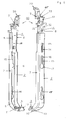
- Figure 1 shows a perspective side view of a holding device 1 in a front and rear view, consisting of a screwed L-shaped bent angle section 2 as a wall bracket, a receiving element 3 for a radiator, not shown, and a height-adjustable support bracket 4 with a retractable body 5.
- Das Angle profile 2 has a U-shaped cross-section, wherein the outgoing legs 6, 7 in the upper part in part have a right-angled inwardly directed fold 8. The fold 8 rests with its flat side on the guide plate (18) and serves to guide it within the wall bracket.
- the angle section 2 is made straight in the upper area, while at the bottom of a bent by about 60 to 90 degrees angle profile end 9 is provided for fixing the receiving element 3.
- the trained legs 6, 7 extend from the upper end of the angle section 2 into the angle profile end 9 in order to achieve a sufficient stiffening of the wall bracket, wherein the legs 6, 7 decrease in width to the angle profile end 9.
- the receiving element 3 is fixed, which has a plurality of sawtooth-shaped recesses 11 and merges in the front region in a raised projection 12, so that the inserted radiator can not slip off.
- the radiator not shown, can be inserted into the existing sawtooth-shaped recesses 11 or recess and thus allows an immovable recording.
- the receiving element 3 may be designed to be interchangeable in a further embodiment of the invention and corresponding to the radiator shape to be fixed deviating dimensions and recesses.
- the angle section 2 has a slot 14 and three openings 15, which consist of a longitudinal slot 16 and an enlarged bore 17.
- the apertures 15 are provided, for example, for fastening the angle section 2 to a wall, wherein not shown fastening bolts engage through the longitudinal slot 16 through existing dowel holes.
- the opening 15 with longitudinal slot 16 and enlarged bore 17 may also be used to accommodate any other necessary aids for stabilizing the radiator.
- Above the openings 15 is the slot 14, which is provided for locking attachment of the retaining bracket 4.
- both parts are captively connected.
- the delivery of the holding device 1 can hereby be done in 2 parts, for example, the radiator is delivered with matching retaining bracket 4 and the retaining bracket 4 needs to be inserted subsequently only in an existing or separate supplied wall bracket or angle section 2.
- the desired combination can be assembled at the last moment at the factory. As a result, for example, the storage can be reduced and leads to a saving of storage space and costs.
- the retaining bracket 4 consists of a continuously insertable body 5, which is guided between the legs 6, 7 of the angle section 2 and is equipped for reinforcement with a guide plate 18.
- a clamping bracket 19 with an integrally formed, exchangeable hook 20 for gripping around the upper radiator end can be screwed to the guide plate 18.
- Of the Base 5 is connected via two integrally formed oppositely oriented retaining claws 21, 22 with the guide plate 18, wherein the retaining claws 21, 22 engage through the guide plate 18 through an opening 23 therethrough.
- the retaining bracket 4 can be completely pre-assembled without the items can fall apart.
- this lateral leg 46, 47 which engage around the main body 5 in part.
- the guide plate 18 also has at the end facing up an angled leg 24 which has a slot 25 for receiving a bolt 31.
- a square nut 27 is used for screwing with the bolt 31.
- the clamping bracket 19 has a slot 33 for receiving the bolt 31, which is arranged corresponding to the slot 25 and a mutual displacement of clamping bracket 19 and leg 24 allows.
- the support bracket 4 can be equipped with several different clamps 19, for example, for vertical radiators, clad or unclad radiators.
- the retaining bracket 4 is shown in Figure 2 with their individual parts before assembly and in Figure 3 after assembly in a perspective view.
- the base body 5 is, as already stated, reinforced by the guide plate 18 and has to receive a locking element 34 has a semi-circular recess 35 with obliquely expiring lateral openings 36, 37.
- a pin 38 is integrally formed, which on one side has a bearing pin 39 on which the arcuate locking element 34 made of spring steel with a trough 40 is applied.
- the trough 40 is in this case formed in a right-angled leg 41, which simultaneously ensures a lateral guidance of the locking element 34 with respect to the pin 38 within the main body 5.
- the two front ends 42, 43 of the locking element 34 protrude out of the lateral openings 36, 37 of the base body and lie after installation partially on the upper or lower surface of the openings 36, 37, so that in the case of compression of the two legs 32 a slight bending of the locking elements 34 inwards takes place, whereby at the same time the front ends 42, 43 are lifted from the inner walls of the angle section 2 ( Figure 1) or the leg surfaces and allow pulling out of the entire retaining bracket 4 ( Figure 3) upwards.
- the protruding ends of the legs 32 are formed at right angles and thus lie in the lowest position directly on the upper edge of the angle section 2 ( Figure 1).
- a locking element 48 which is connected at one end in one piece with the angled end of a leg 32 and the other end with the angled end of the opposite leg 32 is lockable.
- the locking member 48 is resiliently mounted and allows a releasable locking with the angled end of the opposite leg 32, a recess 49 is present, which extends into the angled portion of the leg 32, so that the locking member 48 is held on the one hand to the outside under tension and on the other hand compression is possible.
- a recess 51 is formed, so that the free end 50 can engage in a groove 52 of the opposite angled end of the leg 32.
- the groove 52 in this case goes into a clamping nose 53, behind which the free end 50 of the locking element 48 is clamped. So that the lock can be released with a suitable tool, a gap 54 (FIG. 4) remains between the locking element 48 and the angled end of the leg 32 after locking, so that engagement of a tool 55, as shown in FIG. 4 for example, is possible ,
- the locking element 48 is hooked to the clamping nose 53, the two formed pressure surfaces 44, can not be compressed. Only after releasing the lock 48 is it possible to actuate the two pressure surfaces 44, and compress the two legs 32, so that the retaining bracket 4 can be pulled upwards out of the angle section 2 or possibly even removed.
- FIG. 3 shows the completely preassembled holding console 4 with main body 5, guide plate 18, locking element 48 and screwed clamping element 19. From the perspective view it is very clear how the blocking element 34 rests in the existing recess 35 of the main body 5 and with its lateral end faces 42 , 43 from the existing ones Openings 36, 37 protrudes. If the retaining bracket 4 is inserted into the upper end of the angle section 2, the end faces 42, 43 of the locking element 34 come to rest on the inner surfaces of the legs 6, 7 and are slightly compressed inwardly.
- Figure 4 shows the upper end of the holding device 1 with the holding bracket 4, in the right half of the figure with closed locking element 48 with a tool 55 for releasing the lock and in the left half of the figure with open locking element 48.
- the clamping lug 53 engages behind free end 50 of the locking element 48, the clamping lug 53 to form a groove 54 into which the tool 55, such as a screwdriver, can be used and is used to release the locking element 48.
- the recess 49 is compressed to the extent that sufficient spring preload arises, after releasing the lock, the locking element 48 can move upwards.
- FIG. 5 shows, in a perspective view, another holding device 60 according to the invention in the assembled state in a front and rear view, this largely corresponding to the holding device known from FIG.
- the retaining bracket 4 is shown in Figure 6 with their individual parts before assembly and in Figure 7 after assembly in a perspective view. From Figure 6, the Verrieglungselement 61 is very clearly visible, while Figure 7 shows the complete preassembled retaining bracket 4 with base 5, guide plate 18, locking element 61 and festgeschraubtem clamping element 19.
- the holding device 60 consists of an angle section 2 with a receiving element 3 and a holding bracket 4. A difference from the embodiment of Figure 1 is only that a locking element 61 is used to lock the two legs 32.
- the locking member 61 is arcuate and provided with two outgoing legs 62, 63 ( Figure 6) which form a right angle to each other, wherein in the upper leg 63 has a through hole 64 through which a bolt 65 into a threaded bore 66th of the guide plate 18 can engage.
- the leg 62 comes after assembly between the inner sides of the elastically shaped legs 32 of the main body 5 zuo and thus prevents compression of the two legs 32.
- the clamping bracket 19 has for receiving the bolt 65 has a slot 67 which korrospondierend to the through hole 64 and ., The threaded hole 66 is arranged.
- the retaining bracket 4 can be equipped with several different clamping brackets 19, for example, for vertically clad or unclad radiators.
- the locking element 34 rests in the existing recess 35 of the base body 5 and protrudes with its lateral end faces 42, 43 from the existing openings 36, 37. If the retaining bracket 4 is inserted into the upper end of the angle section 2, the end faces 42, 43 of the locking element 34 come to rest on the inner surfaces of the legs 6, 7 and are slightly compressed by them. The fact that it is spring steel strip, however, a corresponding counterforce is generated here which ensures sufficient friction between the end faces 42, 43 and the legs 6, 7, so that in the case of the attempted pulling out without squeezing the two legs 32 sufficient resistance available is that blocks the retaining bracket 4.
Landscapes
- Engineering & Computer Science (AREA)
- Physics & Mathematics (AREA)
- Thermal Sciences (AREA)
- Chemical & Material Sciences (AREA)
- Combustion & Propulsion (AREA)
- Mechanical Engineering (AREA)
- General Engineering & Computer Science (AREA)
- Clamps And Clips (AREA)
- Cooling Or The Like Of Electrical Apparatus (AREA)
- Connection Of Plates (AREA)
Claims (17)
- Dispositif de maintien (1, 60), en particulier pour des radiateurs à plaques, composé d'une console murale (2) inamovible et d'une console de maintien (4) mobile par rapport à la console murale, dans lequel
la console murale comporte au moins un élément récepteur (3) inférieur fixe pour le radiateur et la console de maintien (4) à hauteur réglable est reçue dans l'extrémité opposée de la console murale,
la console de maintien (4) comporte un élément de serrage déplaçable en continu à la hauteur correspondante et constitué d'un corps de base (5) qui peut être inséré dans la console murale et qui comporte au moins une branche (32) façonnée et élastique ainsi qu'un élément d'arrêt (34) monté dans l'au moins une branche (32) et
le corps de base (5) est parallélépipédique et reçoit l'élément d'arrêt qui dépasse de deux ouvertures (36, 37) latérales du corps de base (5),
caractérisé en ce que le corps de base (5) comporte un creux (35) pour recevoir l'élément d'arrêt (34), un tenon (38), sur lequel repose en le soutenant l'élément d'arrêt (34) par une surface latérale et/ou une surface d'appui, étant formé dans le creux (35). - Dispositif de maintien selon la revendication 1, caractérisé en ce que deux branches (32) élastiques dans lesquelles est guidé l'élément d'arrêt (34) sont façonnées sur le corps de base (5).
- Dispositif de maintien selon la revendication 2, caractérisé en ce que les extrémités des deux branches (32) du corps de base (5) dépassent vers le haut de la console murale et comportent chacune une surface de pression (44) façonnée d'une seule pièce en dépassant de la largeur de la console murale ou sont coudées à l'extrémité et comportent une surface de pression (44) façonnée d'une seule pièce.
- Dispositif de maintien selon la revendication 1, 2 ou 3, caractérisé en ce que l'élément d'arrêt (34) est en acier moulé pour ressort en forme d'arc, dont les surfaces frontales (42, 43) dépassent des ouvertures (36, 37) du corps de base (5).
- Dispositif de maintien selon une ou plusieurs des revendications 1 à 4, caractérisé en ce que sur le tenon (38) est façonné un tourillon sur lequel repose l'élément d'arrêt (34) par une surface d'appui correspondante.
- Dispositif de maintien selon la revendication 5, caractérisé en ce que la surface d'appui de l'élément d'arrêt (34) est une cuvette (40) semi-circulaire qui repose sur le pivot (39).
- Dispositif de maintien selon la revendication 4 et 5, caractérisé en ce que l'arc de l'élément d'arrêt (34) s'appuie à l'intérieur du corps de base (5) en direction d'insertion et que les surfaces frontales (42, 43) entrent en contact avec les parois intérieures de la console murale en passant par les ouvertures (36, 37) existantes du corps de base (5), le contact de l'élément d'arrêt (34) pouvant être supprimé en comprimant les branches (32).
- Dispositif de maintien selon une ou plusieurs des revendications 1 à 7, caractérisé en ce que le corps de base (5) en matière plastique est renforcé par une tôle de guidage (18), la tôle de guidage (18) étant munie d' un passage (23) de préférence rectangulaire dans lequel passent deux griffes de maintien (21, 22) du corps de base (5) à des fins de fixation et de verrouillage.
- Dispositif de maintien selon une ou plusieurs des revendications 1 à 8, caractérisé en ce que le corps de base (5) est muni d'un bec (45) façonné d'une seule pièce qui dépasse d'une surface latérale et se bloque dans un trou oblong (14) de la cornière (2) après le montage, le bec (45) étant muni d'un biseau destiné à l'enfoncement en direction du mouvement vers la cornière (2).
- Dispositif de maintien selon une ou plusieurs des revendications 1 à 9, caractérisé en ce que le corps de base (5) prémonté avec l'élément d'arrêt (34) et la tôle de guidage (18) est conçu pour être inséré par le haut dans la console murale.
- Dispositif de maintien selon une ou plusieurs des revendications 1 à 10, caractérisé en ce que la console de maintien (4) comprend un corps de base (5) guidé en continu dans la console murale et un étrier de serrage (19) qui passe par dessus le radiateur, l'étrier de serrage (19), qui peut glisser par rapport au corps de base (5), étant fixé par exemple par un boulon.
- Dispositif de maintien selon une ou plusieurs des revendications 1 à 11, caractérisé en ce que l'élément récepteur (3) fixe comporte plusieurs creux (11) adaptés au radiateur, de préférence munis d'évidements en dents de scie.
- Dispositif de maintien selon une ou plusieurs des revendications 1 à 12, caractérisé en ce que l'élément récepteur (3) fixe de la console murale (2) peut être remplacé grâce à un dispositif d'engagement.
- Dispositif de maintien selon une ou plusieurs des revendications 1 à 13, caractérisé en ce que les branches (32) élastiques peuvent être bloquées l'une par rapport à l'autre par un élément d'arrêt (48, 61).
- Dispositif de maintien selon une ou plusieurs des revendications 1 à 14, caractérisé en ce que l'élément d'arrêt (48) est formé d'une seule pièce à l'extrémité coudée d'une branche (32) en formant un évidement (49) et peut être verrouillé par encliquetage sur l'extrémité coudée opposée de la deuxième branche (32).
- Dispositif de maintien selon une ou plusieurs des revendications 1 à 15, caractérisé en ce que l'élément d'arrêt (48) comporte à son extrémité libre (50) un retrait (51) formé pour correspondre à une rainure (52) munie d'un bec de serrage (53) à l'extrémité coudée opposée de la branche (32).
- Dispositif de maintien selon une ou plusieurs des revendications 1 à 16, caractérisé en ce que les deux branches (32) élastiques peuvent être bloquées par un élément de verrouillage (61) posé sur la tôle de guidage (18) et maintenu à l'aide d'un boulon (31, 65).
Applications Claiming Priority (4)
| Application Number | Priority Date | Filing Date | Title |
|---|---|---|---|
| DE20217874U DE20217874U1 (de) | 2002-11-18 | 2002-11-18 | Haltevorrichtung |
| DE20217874U | 2002-11-18 | ||
| DE20304332U | 2003-03-17 | ||
| DE20304332U DE20304332U1 (de) | 2002-11-18 | 2003-03-17 | Haltevorrichtung |
Publications (3)
| Publication Number | Publication Date |
|---|---|
| EP1420211A2 EP1420211A2 (fr) | 2004-05-19 |
| EP1420211A3 EP1420211A3 (fr) | 2004-10-13 |
| EP1420211B1 true EP1420211B1 (fr) | 2006-12-06 |
Family
ID=32178540
Family Applications (1)
| Application Number | Title | Priority Date | Filing Date |
|---|---|---|---|
| EP03025140A Expired - Lifetime EP1420211B1 (fr) | 2002-11-18 | 2003-10-31 | Dispositif de support mural d'un radiateur |
Country Status (3)
| Country | Link |
|---|---|
| EP (1) | EP1420211B1 (fr) |
| AT (1) | ATE347674T1 (fr) |
| DE (1) | DE50305892D1 (fr) |
Families Citing this family (2)
| Publication number | Priority date | Publication date | Assignee | Title |
|---|---|---|---|---|
| SE528748C2 (sv) * | 2005-06-23 | 2007-02-06 | Sigarth Ab | Monteringsanordning för radiator |
| DE202009018231U1 (de) * | 2009-07-30 | 2011-05-05 | Wemefa Horst Christopeit Gmbh | Vorrichtung zur Halterung eines Heizkörpers |
Family Cites Families (4)
| Publication number | Priority date | Publication date | Assignee | Title |
|---|---|---|---|---|
| DE4301943C2 (de) * | 1993-01-25 | 1997-01-30 | H G Gottbehuet Gmbh & Co Kg | Wandkonsole für Heizkörper |
| DE20108499U1 (de) * | 2000-10-06 | 2001-08-16 | Ulamo Beheer B.V., Ulft | Haltevorrichtung |
| IT1315759B1 (it) * | 2000-11-27 | 2003-03-18 | Mb Srl | Dispositivo di ancoraggio a muro per radiatori |
| DE20115976U1 (de) * | 2001-09-28 | 2001-12-13 | Ulamo Beheer B.V., Ulft | Haltevorrichtung für Heizkörper |
-
2003
- 2003-10-31 EP EP03025140A patent/EP1420211B1/fr not_active Expired - Lifetime
- 2003-10-31 DE DE50305892T patent/DE50305892D1/de not_active Expired - Lifetime
- 2003-10-31 AT AT03025140T patent/ATE347674T1/de not_active IP Right Cessation
Also Published As
| Publication number | Publication date |
|---|---|
| DE50305892D1 (de) | 2007-01-18 |
| EP1420211A3 (fr) | 2004-10-13 |
| EP1420211A2 (fr) | 2004-05-19 |
| ATE347674T1 (de) | 2006-12-15 |
Similar Documents
| Publication | Publication Date | Title |
|---|---|---|
| EP2013493B1 (fr) | Dispositif de fixation | |
| EP2009293B1 (fr) | Dispositif destiné à lier un rail de profilé avec un autre composant | |
| DE1779745C3 (de) | Vorrichtung zum Verbinden einer ersten Möbelwand mit einer zweiten Möbelwand | |
| DE19536316C1 (de) | Klammer zur Halterung von Rohren | |
| WO2018228877A1 (fr) | Fixation de rail de support | |
| DE102006059863B3 (de) | Befestigungsvorrichtung zur Befestigung eines elektrischen oder elektronischen Geräts auf einer Hutschiene | |
| WO2016012081A1 (fr) | Dispositif de fixation d'un rail de montage | |
| DE102006019256A1 (de) | Befestigungsvorrichtung | |
| DE102011010828B4 (de) | Klemmvorrichtung zur lösbaren Befestigung eines Gerätegehäuses an einer Profilschiene | |
| DE102005051678B4 (de) | Vorrichtung zum Befestigen eines Anbauteiles an einem Trägerteil | |
| DE202010017706U1 (de) | Spannvorrichtung für Vorhangseil | |
| DE20319556U1 (de) | Vorrichtung zum Verbinden eines Trägerteiles mit einem Anbauteil | |
| EP1420211B1 (fr) | Dispositif de support mural d'un radiateur | |
| DE9216499U1 (de) | Rohrschelle | |
| DE102006051829B4 (de) | Haltersystem für langgestreckte Gegenstände | |
| DE202006019411U1 (de) | Befestigungsvorrichtung | |
| DE102012004679B4 (de) | Befestigungseinrichtung zur Festlegung eines Heiz- oder Kühlkörpers | |
| EP1843104B1 (fr) | Dispositif de support réglable | |
| DE20304332U1 (de) | Haltevorrichtung | |
| EP3599338A1 (fr) | Dispositif de suspension permettant de fixer des stores | |
| DE102004057705A1 (de) | Klemmvorrichtung zur lösbaren Befestigung eines Gerätegehäuses an einer Profilschiene | |
| DE19709183B4 (de) | Deckenelement mit einer Verriegelungsvorrichtung | |
| DE10312015B4 (de) | Befestigungsvorrichtung für langgestreckte, flache Gegenstände, insbesondere Flachbandleitungen | |
| DE202005019601U1 (de) | Haltersystem für langgestreckte Gegenstände | |
| EP2730196B1 (fr) | Dispositif permettant de fixer une partie avant à une partie latérale d'une pièce de meuble mobile |
Legal Events
| Date | Code | Title | Description |
|---|---|---|---|
| PUAI | Public reference made under article 153(3) epc to a published international application that has entered the european phase |
Free format text: ORIGINAL CODE: 0009012 |
|
| AK | Designated contracting states |
Kind code of ref document: A2 Designated state(s): AT BE BG CH CY CZ DE DK EE ES FI FR GB GR HU IE IT LI LU MC NL PT RO SE SI SK TR |
|
| AX | Request for extension of the european patent |
Extension state: AL LT LV MK |
|
| PUAL | Search report despatched |
Free format text: ORIGINAL CODE: 0009013 |
|
| AK | Designated contracting states |
Kind code of ref document: A3 Designated state(s): AT BE BG CH CY CZ DE DK EE ES FI FR GB GR HU IE IT LI LU MC NL PT RO SE SI SK TR |
|
| AX | Request for extension of the european patent |
Extension state: AL LT LV MK |
|
| 17P | Request for examination filed |
Effective date: 20041111 |
|
| AKX | Designation fees paid |
Designated state(s): AT BE BG CH CY CZ DE DK EE ES FI FR GB GR HU IE IT LI LU MC NL PT RO SE SI SK TR |
|
| GRAP | Despatch of communication of intention to grant a patent |
Free format text: ORIGINAL CODE: EPIDOSNIGR1 |
|
| GRAS | Grant fee paid |
Free format text: ORIGINAL CODE: EPIDOSNIGR3 |
|
| GRAA | (expected) grant |
Free format text: ORIGINAL CODE: 0009210 |
|
| AK | Designated contracting states |
Kind code of ref document: B1 Designated state(s): AT BE BG CH CY CZ DE DK EE ES FI FR GB GR HU IE IT LI LU MC NL PT RO SE SI SK TR |
|
| PG25 | Lapsed in a contracting state [announced via postgrant information from national office to epo] |
Ref country code: IT Free format text: LAPSE BECAUSE OF FAILURE TO SUBMIT A TRANSLATION OF THE DESCRIPTION OR TO PAY THE FEE WITHIN THE PRESCRIBED TIME-LIMIT;WARNING: LAPSES OF ITALIAN PATENTS WITH EFFECTIVE DATE BEFORE 2007 MAY HAVE OCCURRED AT ANY TIME BEFORE 2007. THE CORRECT EFFECTIVE DATE MAY BE DIFFERENT FROM THE ONE RECORDED. Effective date: 20061206 Ref country code: IE Free format text: LAPSE BECAUSE OF FAILURE TO SUBMIT A TRANSLATION OF THE DESCRIPTION OR TO PAY THE FEE WITHIN THE PRESCRIBED TIME-LIMIT Effective date: 20061206 Ref country code: CZ Free format text: LAPSE BECAUSE OF FAILURE TO SUBMIT A TRANSLATION OF THE DESCRIPTION OR TO PAY THE FEE WITHIN THE PRESCRIBED TIME-LIMIT Effective date: 20061206 Ref country code: RO Free format text: LAPSE BECAUSE OF FAILURE TO SUBMIT A TRANSLATION OF THE DESCRIPTION OR TO PAY THE FEE WITHIN THE PRESCRIBED TIME-LIMIT Effective date: 20061206 Ref country code: SK Free format text: LAPSE BECAUSE OF FAILURE TO SUBMIT A TRANSLATION OF THE DESCRIPTION OR TO PAY THE FEE WITHIN THE PRESCRIBED TIME-LIMIT Effective date: 20061206 Ref country code: DK Free format text: LAPSE BECAUSE OF FAILURE TO SUBMIT A TRANSLATION OF THE DESCRIPTION OR TO PAY THE FEE WITHIN THE PRESCRIBED TIME-LIMIT Effective date: 20061206 Ref country code: SI Free format text: LAPSE BECAUSE OF FAILURE TO SUBMIT A TRANSLATION OF THE DESCRIPTION OR TO PAY THE FEE WITHIN THE PRESCRIBED TIME-LIMIT Effective date: 20061206 Ref country code: FI Free format text: LAPSE BECAUSE OF FAILURE TO SUBMIT A TRANSLATION OF THE DESCRIPTION OR TO PAY THE FEE WITHIN THE PRESCRIBED TIME-LIMIT Effective date: 20061206 |
|
| REG | Reference to a national code |
Ref country code: GB Ref legal event code: FG4D Free format text: NOT ENGLISH |
|
| REG | Reference to a national code |
Ref country code: CH Ref legal event code: EP |
|
| REG | Reference to a national code |
Ref country code: IE Ref legal event code: FG4D Free format text: LANGUAGE OF EP DOCUMENT: GERMAN |
|
| REF | Corresponds to: |
Ref document number: 50305892 Country of ref document: DE Date of ref document: 20070118 Kind code of ref document: P |
|
| GBT | Gb: translation of ep patent filed (gb section 77(6)(a)/1977) |
Effective date: 20070110 |
|
| PG25 | Lapsed in a contracting state [announced via postgrant information from national office to epo] |
Ref country code: SE Free format text: LAPSE BECAUSE OF FAILURE TO SUBMIT A TRANSLATION OF THE DESCRIPTION OR TO PAY THE FEE WITHIN THE PRESCRIBED TIME-LIMIT Effective date: 20070306 Ref country code: BG Free format text: LAPSE BECAUSE OF FAILURE TO SUBMIT A TRANSLATION OF THE DESCRIPTION OR TO PAY THE FEE WITHIN THE PRESCRIBED TIME-LIMIT Effective date: 20070306 |
|
| PG25 | Lapsed in a contracting state [announced via postgrant information from national office to epo] |
Ref country code: ES Free format text: LAPSE BECAUSE OF FAILURE TO SUBMIT A TRANSLATION OF THE DESCRIPTION OR TO PAY THE FEE WITHIN THE PRESCRIBED TIME-LIMIT Effective date: 20070317 |
|
| PG25 | Lapsed in a contracting state [announced via postgrant information from national office to epo] |
Ref country code: PT Free format text: LAPSE BECAUSE OF FAILURE TO SUBMIT A TRANSLATION OF THE DESCRIPTION OR TO PAY THE FEE WITHIN THE PRESCRIBED TIME-LIMIT Effective date: 20070507 |
|
| ET | Fr: translation filed | ||
| PLBE | No opposition filed within time limit |
Free format text: ORIGINAL CODE: 0009261 |
|
| STAA | Information on the status of an ep patent application or granted ep patent |
Free format text: STATUS: NO OPPOSITION FILED WITHIN TIME LIMIT |
|
| 26N | No opposition filed |
Effective date: 20070907 |
|
| PG25 | Lapsed in a contracting state [announced via postgrant information from national office to epo] |
Ref country code: GR Free format text: LAPSE BECAUSE OF FAILURE TO SUBMIT A TRANSLATION OF THE DESCRIPTION OR TO PAY THE FEE WITHIN THE PRESCRIBED TIME-LIMIT Effective date: 20070307 |
|
| PG25 | Lapsed in a contracting state [announced via postgrant information from national office to epo] |
Ref country code: MC Free format text: LAPSE BECAUSE OF NON-PAYMENT OF DUE FEES Effective date: 20071031 |
|
| REG | Reference to a national code |
Ref country code: CH Ref legal event code: PL |
|
| PG25 | Lapsed in a contracting state [announced via postgrant information from national office to epo] |
Ref country code: CH Free format text: LAPSE BECAUSE OF NON-PAYMENT OF DUE FEES Effective date: 20071031 Ref country code: LI Free format text: LAPSE BECAUSE OF NON-PAYMENT OF DUE FEES Effective date: 20071031 |
|
| PG25 | Lapsed in a contracting state [announced via postgrant information from national office to epo] |
Ref country code: EE Free format text: LAPSE BECAUSE OF FAILURE TO SUBMIT A TRANSLATION OF THE DESCRIPTION OR TO PAY THE FEE WITHIN THE PRESCRIBED TIME-LIMIT Effective date: 20061206 |
|
| PG25 | Lapsed in a contracting state [announced via postgrant information from national office to epo] |
Ref country code: AT Free format text: LAPSE BECAUSE OF NON-PAYMENT OF DUE FEES Effective date: 20071031 |
|
| PG25 | Lapsed in a contracting state [announced via postgrant information from national office to epo] |
Ref country code: CY Free format text: LAPSE BECAUSE OF FAILURE TO SUBMIT A TRANSLATION OF THE DESCRIPTION OR TO PAY THE FEE WITHIN THE PRESCRIBED TIME-LIMIT Effective date: 20061206 Ref country code: LU Free format text: LAPSE BECAUSE OF NON-PAYMENT OF DUE FEES Effective date: 20071031 |
|
| PG25 | Lapsed in a contracting state [announced via postgrant information from national office to epo] |
Ref country code: HU Free format text: LAPSE BECAUSE OF FAILURE TO SUBMIT A TRANSLATION OF THE DESCRIPTION OR TO PAY THE FEE WITHIN THE PRESCRIBED TIME-LIMIT Effective date: 20070607 |
|
| PGFP | Annual fee paid to national office [announced via postgrant information from national office to epo] |
Ref country code: NL Payment date: 20101021 Year of fee payment: 8 |
|
| PGFP | Annual fee paid to national office [announced via postgrant information from national office to epo] |
Ref country code: TR Payment date: 20101025 Year of fee payment: 8 Ref country code: GB Payment date: 20101021 Year of fee payment: 8 Ref country code: BE Payment date: 20101022 Year of fee payment: 8 |
|
| BERE | Be: lapsed |
Owner name: ULAMO BEHEER B.V. Effective date: 20111031 |
|
| REG | Reference to a national code |
Ref country code: NL Ref legal event code: V1 Effective date: 20120501 |
|
| PG25 | Lapsed in a contracting state [announced via postgrant information from national office to epo] |
Ref country code: NL Free format text: LAPSE BECAUSE OF NON-PAYMENT OF DUE FEES Effective date: 20120501 Ref country code: BE Free format text: LAPSE BECAUSE OF NON-PAYMENT OF DUE FEES Effective date: 20111031 |
|
| GBPC | Gb: european patent ceased through non-payment of renewal fee |
Effective date: 20121031 |
|
| PG25 | Lapsed in a contracting state [announced via postgrant information from national office to epo] |
Ref country code: GB Free format text: LAPSE BECAUSE OF NON-PAYMENT OF DUE FEES Effective date: 20121031 |
|
| PGFP | Annual fee paid to national office [announced via postgrant information from national office to epo] |
Ref country code: FR Payment date: 20131018 Year of fee payment: 11 |
|
| PG25 | Lapsed in a contracting state [announced via postgrant information from national office to epo] |
Ref country code: TR Free format text: LAPSE BECAUSE OF NON-PAYMENT OF DUE FEES Effective date: 20121031 |
|
| PGFP | Annual fee paid to national office [announced via postgrant information from national office to epo] |
Ref country code: DE Payment date: 20131220 Year of fee payment: 11 |
|
| REG | Reference to a national code |
Ref country code: DE Ref legal event code: R119 Ref document number: 50305892 Country of ref document: DE |
|
| PG25 | Lapsed in a contracting state [announced via postgrant information from national office to epo] |
Ref country code: DE Free format text: LAPSE BECAUSE OF NON-PAYMENT OF DUE FEES Effective date: 20150501 |
|
| REG | Reference to a national code |
Ref country code: FR Ref legal event code: ST Effective date: 20150630 |
|
| PG25 | Lapsed in a contracting state [announced via postgrant information from national office to epo] |
Ref country code: FR Free format text: LAPSE BECAUSE OF NON-PAYMENT OF DUE FEES Effective date: 20141031 |