EP1420165A2 - Method and apparatus of detecting the condition of a centrifugal pump - Google Patents
Method and apparatus of detecting the condition of a centrifugal pump Download PDFInfo
- Publication number
- EP1420165A2 EP1420165A2 EP20030025234 EP03025234A EP1420165A2 EP 1420165 A2 EP1420165 A2 EP 1420165A2 EP 20030025234 EP20030025234 EP 20030025234 EP 03025234 A EP03025234 A EP 03025234A EP 1420165 A2 EP1420165 A2 EP 1420165A2
- Authority
- EP
- European Patent Office
- Prior art keywords
- pump
- real
- power signal
- frequency spectrum
- time
- Prior art date
- Legal status (The legal status is an assumption and is not a legal conclusion. Google has not performed a legal analysis and makes no representation as to the accuracy of the status listed.)
- Withdrawn
Links
- 238000000034 method Methods 0.000 title claims description 20
- 238000001228 spectrum Methods 0.000 claims description 40
- 238000010183 spectrum analysis Methods 0.000 claims description 12
- 238000004590 computer program Methods 0.000 claims description 10
- 238000003860 storage Methods 0.000 claims description 10
- 230000003595 spectral effect Effects 0.000 claims description 9
- 238000001914 filtration Methods 0.000 claims description 5
- 238000012544 monitoring process Methods 0.000 claims description 4
- 230000011664 signaling Effects 0.000 claims description 4
- 239000007858 starting material Substances 0.000 claims description 3
- 238000012423 maintenance Methods 0.000 abstract description 3
- 238000004364 calculation method Methods 0.000 description 9
- 238000004422 calculation algorithm Methods 0.000 description 8
- 238000005070 sampling Methods 0.000 description 8
- 230000008569 process Effects 0.000 description 7
- 230000001143 conditioned effect Effects 0.000 description 6
- 238000004458 analytical method Methods 0.000 description 3
- 238000013459 approach Methods 0.000 description 3
- 238000001514 detection method Methods 0.000 description 3
- 238000012935 Averaging Methods 0.000 description 2
- 230000003750 conditioning effect Effects 0.000 description 2
- 230000006870 function Effects 0.000 description 2
- 238000009834 vaporization Methods 0.000 description 2
- 230000008016 vaporization Effects 0.000 description 2
- 230000004913 activation Effects 0.000 description 1
- 230000003321 amplification Effects 0.000 description 1
- 230000003139 buffering effect Effects 0.000 description 1
- 230000015556 catabolic process Effects 0.000 description 1
- 238000013461 design Methods 0.000 description 1
- 239000003651 drinking water Substances 0.000 description 1
- 235000020188 drinking water Nutrition 0.000 description 1
- 230000000694 effects Effects 0.000 description 1
- 239000012530 fluid Substances 0.000 description 1
- 230000006698 induction Effects 0.000 description 1
- 238000003973 irrigation Methods 0.000 description 1
- 230000002262 irrigation Effects 0.000 description 1
- 238000004519 manufacturing process Methods 0.000 description 1
- 230000007246 mechanism Effects 0.000 description 1
- 238000012986 modification Methods 0.000 description 1
- 230000004048 modification Effects 0.000 description 1
- 238000003199 nucleic acid amplification method Methods 0.000 description 1
- 230000002085 persistent effect Effects 0.000 description 1
- 238000012545 processing Methods 0.000 description 1
- 238000005086 pumping Methods 0.000 description 1
- 238000012546 transfer Methods 0.000 description 1
- 230000001960 triggered effect Effects 0.000 description 1
- 230000000007 visual effect Effects 0.000 description 1
- 238000011179 visual inspection Methods 0.000 description 1
Images


Classifications
-
- F—MECHANICAL ENGINEERING; LIGHTING; HEATING; WEAPONS; BLASTING
- F04—POSITIVE - DISPLACEMENT MACHINES FOR LIQUIDS; PUMPS FOR LIQUIDS OR ELASTIC FLUIDS
- F04B—POSITIVE-DISPLACEMENT MACHINES FOR LIQUIDS; PUMPS
- F04B49/00—Control, e.g. of pump delivery, or pump pressure of, or safety measures for, machines, pumps, or pumping installations, not otherwise provided for, or of interest apart from, groups F04B1/00 - F04B47/00
- F04B49/06—Control using electricity
- F04B49/065—Control using electricity and making use of computers
-
- F—MECHANICAL ENGINEERING; LIGHTING; HEATING; WEAPONS; BLASTING
- F04—POSITIVE - DISPLACEMENT MACHINES FOR LIQUIDS; PUMPS FOR LIQUIDS OR ELASTIC FLUIDS
- F04D—NON-POSITIVE-DISPLACEMENT PUMPS
- F04D15/00—Control, e.g. regulation, of pumps, pumping installations or systems
- F04D15/02—Stopping of pumps, or operating valves, on occurrence of unwanted conditions
- F04D15/0209—Stopping of pumps, or operating valves, on occurrence of unwanted conditions responsive to a condition of the working fluid
- F04D15/0218—Stopping of pumps, or operating valves, on occurrence of unwanted conditions responsive to a condition of the working fluid the condition being a liquid level or a lack of liquid supply
- F04D15/0236—Lack of liquid level being detected by analysing the parameters of the electric drive, e.g. current or power consumption
-
- F—MECHANICAL ENGINEERING; LIGHTING; HEATING; WEAPONS; BLASTING
- F04—POSITIVE - DISPLACEMENT MACHINES FOR LIQUIDS; PUMPS FOR LIQUIDS OR ELASTIC FLUIDS
- F04D—NON-POSITIVE-DISPLACEMENT PUMPS
- F04D29/00—Details, component parts, or accessories
- F04D29/66—Combating cavitation, whirls, noise, vibration or the like; Balancing
- F04D29/669—Combating cavitation, whirls, noise, vibration or the like; Balancing especially adapted for liquid pumps
Definitions
- the present invention relates generally to centrifugal pumps, and more particularly, to a method and apparatus of detecting low flow and/or cavitation in a centrifugal pump using voltage and current data acquired from voltage and current sensors in the pump motor controller assembly.
- Submersible motor centrifugal pumps are commonly used for drinking water supply, irrigation, and de-watering as well as in offshore applications.
- both the motor as well as the pump are submerged and installed in deep wells down to 1,000 m.
- motor power often reaches up to 2,000 kW and voltage up to 10,000 V.
- condition monitoring and detection of undesirable conditions at an early stage are often difficult.
- Low flow and cavitation in centrifugal pumps may be caused by several conditions.
- cavitation can result when air bubbles form in low pressure regions inside the pump.
- "Low flow” or restricted output of the pump occurs as a result of restriction due to obstructions at the input or output of the pump. Recirculation of fluid within the pump housing can result from such a restriction. The recirculation causes swirling vortices between blades of the impeller. This swirling effect reduces the torque in the pump and ultimately restricts the output of the pump ⁇ clearly, an undesirable condition.
- the present invention is directed to a centrifugal pump wherein voltage and current data are detected from voltage and current sensors in the pump motor controller to determine low flow and/or cavitation in the pump overcoming the aforementioned drawbacks. A power signal is then generated from the voltage and current data and spectrally analyzed to determine the low flow or cavitation in the pump. As such, unwanted operational conditions resulting from improper pump operation may be detected and a warning or maintenance flag provided without additional transducers and other instruments on the motor or pump.
- motor power is used to determine the presence of a low flow and/or cavitation condition in the pump, i.e. a torque loss and vaporization.
- Power is preferably determined from voltage and current data acquired from a three-phase motor.
- a baseline signal is determined from the pump known to be operating in a normal, healthy condition. The baseline signal or data is then used for comparison with equivalent signals derived from operational data so that deviations from normal, healthy operation can be readily identified.
- Voltage and current data are collected for a relatively short period of time such as one second and a corresponding power signal is then generated.
- the power signal is then analyzed with a fast Fourier transform (FFT) or band-pass filtered to locate increased noise levels in the power signal, relative to a baseline signal, within a predetermined frequency range.
- FFT fast Fourier transform
- band-pass filtered By comparing the energy, within the frequency range of interest, of the transformed or filtered signal with the baseline signal, increased noise levels indicating the presence of cavitation or low flow conditions can be readily identified.
- the relative increase in noise level is an indication of the magnitude of the low flow or cavitation.
- a maintenance warning or flag is then provided to an operator or other technician so that, if needed, the pump may be shut down or the operating conditions adjusted to eliminate the cause of the fault condition.
- a motor control for a motor-driven pump includes at least one voltage sensor and at least one current sensor and is configured to receive a voltage and a current signal of the pump in operation from the at least one voltage sensor and at least one current sensor.
- the controller is further configured to determine a power signal from the voltage signal, and the current signal, to generate a real-time spectrum analysis of the power signal and to extract critical features from the spectrum.
- the controller is also configured to determine at least one of a low flow and a cavitation condition in the pump from the spectrum analysis.
- a computer readable storage medium having stored thereon a computer program to detect and signal improper operation of a motor-driven pump.
- the computer program represents a set of instructions that when executed by a processor causes the processor to determine a real-time power signal of power in a pump motor assembly.
- the set of instructions further causes the processor to perform a spectrum analysis on the real-time power signal over several time cycles and generate a real-time frequency spectrum therefrom.
- the computer program compares real-time data with baseline operation of a system known to be in good operating condition and operating at nominal flow conditions.
- the computer program determines differences between the baseline data and the data derived from current operating conditions. If the differences exceed a threshold, the computer program provides an external notification signaling improper operation in the pump.
- a method of monitoring proper operation in a centrifugal pump motor includes the step of generating a baseline frequency spectrum of a pump known to be operating properly.
- the method further includes the step of generating a real-time frequency spectrum of the pump in operation from a power signal derived from voltage and current signals acquired from sensors in a motor of the pump, then extracting from this spectrum the energy contained in a prescribed frequency range. This energy is then compared to that obtained from the baseline frequency spectrum and an undesirable pump operating condition is determined therefrom. If an undesirable condition exists, a signal indicating the presence of the condition is provided.
- the present invention is related to the detection of low flow and/or cavitation conditions in a centrifugal pump having a three-phase motor.
- a motor assembly for a centrifugal pump is shown.
- Motor assembly 10 includes a motor 12 that receives power from a power supply 14.
- the assembly also includes a controller 16 used to monitor as well as control operation of the motor.
- the controller 16 includes a processor 18 that, as will be described in greater detail with respect to Figs. 2-5, implements an algorithm to determine low flow and/or cavitation in the centrifugal pump based on voltage and current data.
- Motor controller assembly 10 further includes a pair of voltage sensors 20 and a pair of current sensors 22.
- voltage and current data may be acquired from only two of the phases of a three-phase motor as voltage and current data for the third phase may be extrapolated from the voltage and current data of the monitored two phases. While the present invention will be described with respect to a three-phase motor, the present invention is equivalently applicable to a single-phase motor.
- the process 24 employs an FFT to generate a spectrum analysis of a power signal based on voltage and current data acquired from sensors in the pump motor.
- the process of detecting a low flow and/or cavitation condition in a centrifugal pump using an FFT begins with the acquisition of voltage and current data 26 using voltage and current sensors present in the motor controller assembly. By acquiring the voltage and current data directly from voltage sensors in the motor controller, it is unnecessary to incorporate additional instrumentation to acquire the voltage and current data as the motor controller typically includes voltage and current sensors. Once the voltage and current signals are acquired, the signals are conditioned at 28.
- Signal conditioning the voltage and current signals includes amplification, buffering, and anti-aliasing of the signals. Once the voltage and current signals are properly conditioned, they are input into an analog-to-digital converter 30 for sampling. From the sampled voltage and current signals, a power signal or calculation is determined at 32. The power signal is determined by multiplying the voltage values and the current values. As a result, a power signal illustrating power in the motor as a function of time may be readily generated. The calculated power signal then undergoes an FFT at 34 to generate a frequency spectrum. By applying an FFT to the power signal, a frequency spectrum can be generated and features of the spectrum compared to those of a baseline frequency spectrum. Based on this comparison 36, an output signal signaling either a low flow and/or cavitating condition in the pump may be output at 38. The output may take a number of forms including audio and visual warnings and shut down of the pump.
- the algorithm or process 40 provides an efficient mechanism to calculate the FFT of motor power and compare spectral energy within a band of frequencies to thresholds established during setup when the pump was known to be operating normally or at or near its best efficiency point. These thresholds or baseline data are acquired during initial setup of the pump motor under a variety of normal operating conditions so that nuances relative to each pump are taken into account when determining the basepoint of operation. Simply, each pump is modeled to determine a baseline data of operation so that variances over time can be readily identified relative to the known healthy and normal operation of the pump.
- voltage and current data is acquired from voltage and current sensors in the motor starter for the pump motor. Specifically, two line-to-line voltages with respect to a common node and line currents for those two lines of a three-phase induction motor are acquired at 42.
- the voltage and current data are then input to an anti-aliasing filter at 44 that provides at least 40 dB of attenuation at a frequency that is one-half the sampling rate. It is recommended that the anti-aliasing filter have less than one dB of pass-band ripple.
- the cutoff frequency should be approximately 1 kHz.
- the anti-aliased signals are then conditioned at 46.
- the conditioned signals are then input to an analog-to-digital converter and sampled at a sampling rate of approximately 5 kHz.
- the sampled signals are then input to a power calculation means 50.
- the power calculation is preferably a three-phase calculation done "on the fly". That is, the power of the pump motor is determined in real-time as the data is acquired. The power is determined by treating one of the motor terminals as a common node and then multiplying the line-to-line voltages with respect to that node by the respective line current. Following the power calculation, the power signals are filtered in real-time at 52 and decimated to a 1024 point dataset which is stored in memory to be used by the FFT at 54. Since the power has a relatively large average value relative to the components of interest, the filter output must be allowed to reach this average value before the acquired data is used for FFT calculations. As will be described in greater detail below, a steady state analysis is performed to ensure that the filter output has reached the average value before the data set used for FFT calculations is saved.
- Filtering of the power signal is done at 52 by an eighth order low pass elliptic filter with a cutoff frequency of 90 Hz, pass-band ripple of less than one dB, and attenuation of 60 dB at 180 Hz. This filtering is required to eliminate aliasing when the data is decimated to the final sampling frequency.
- the cutoff frequency is chosen to permit sensing signals as high as 120 Hz, or about twice the running frequency of a two-pole motor operating on a 60 Hz line.
- the data originally sampled at approximately 5 kHz is decimated at 54 by a factor of 25 to produce an effective sampling rate of about 213.33 Hz.
- the data set for an efficient FFT must be of length to 2 n to produce a spectrum with quality definition.
- it is desirable to have at least 0.4 Hz of spectral resolution, defined by: resolution Fs/Np where Fs is the sampling rate and Np is the number of points in the data set. For an Fs of 213.33 and an Np of 1024, the resolution is about 0.208 Hz.
- An additional factor to consider is avoiding loss of data resolution when executing a fixed point FFT. To do so, it is desirable to use a minimum data set length. The parameters should be chosen so as to lead to reasonable results with relatively short data set lengths. Additionally, it is desirable to avoid the use of a window which would ultimately require additional multiply operations.
- the average value is removed from the data set that is decimated and stored in 54 for use by the FFT process. This eliminates a very large spectral spike at zero frequency as well as to reduce the numerical range that must be dealt with in the FFT procedure thereby permitting the use of fixed point processing.
- the decimated signal then undergoes a 1024 point FFT at 56.
- a digital signal processor is used to apply the FFT and yields results and spectrum values that are the square of the actual amplitude of the signal. Since the square root operation is not trivial, the squared values are used in evaluating the spectrum 58. Because an FFT for a given data set will show some random variation and spectral amplitude when compared to FFTs from other data sets gathered under conditions that are nominally the same, it is preferable to diminish this randomness by averaging several FFTs together. As a result, preferably, four FFTs are averaged at 60 in accordance with the present invention.
- RAM may often be limited
- the result of four separate FFTs prior to computing the average is not stored. That is, the same spectral buckets used to collect results for all four FFTs are used and an average is performed at the end.
- the average results of the four FFTs are then analyzed to include the spectrum between 5 and 25 Hz. This frequency range has been empirically determined to be the range that noise in an instantaneous power signal increases if pump flow is impeded.
- the FFT data within the range are then input to a digital-to-analog converter at 62.
- the resultant signal can then be displayed on an oscilloscope or computer screen for analysis at 64.
- the spectral energy within the band of about 5 to 25 Hz is calculated at 65 and a warning signal or alarm 66 is triggered if the noise energy in this frequency band exceeds a threshold. As such, the noise energy in the frequency band is compared to a baseline signal.
- a single FFT could also be implemented rather than averaging four FFTs provided an adequate number of data points are provided to generate a reliable and usable result.
- the frequency spectrum of the real-time power signal and the baseline can be displayed on a console such that an operator or technician can determine a low flow and/or cavitating condition based on visual inspection of the 5-25 Hz frequency range.
- Other indicators such as warning lights and audio warnings may also be implemented when the acceptable baseline energy for the 5-25Hz range is exceeded on a persistent basis.
- a two-level warning system may be implemented where a condition that narrowly exceeds the baseline actuates a low priority warning light whereas a condition that is significantly higher than the baseline triggers an urgent alarm.
- a steady state analysis is implemented to ensure the integrity of the data acquisition. That is, the data is evaluated for a steady state operating condition by evaluating the average power of the first half of the data set versus that of the second half. For a steady state condition to be present, the average power for the two halves is required to be within one percent of each other. If a non-steady state condition is encountered, the entire FFT data set is discarded and the process starts anew with a new group of four FFTs.
- an alternate algorithm for detecting low flow and/or cavitation in a motor pump utilizes a digital band-pass filter as opposed to an FFT to generate an output that represents only the signal content of the 5 to 25 Hz range of the power signal. Because a filter-based algorithm has less computational burden than an FFT, the filter-based approach is particularly applicable to low cost product implementations. However, if a given motor control product already implements another FFT-based algorithm associated with other control parameters of the motor, the FFT approach may be preferred.
- the digital band-pass algorithm 68 begins with the acquisition of voltage and current data 70.
- the voltage and current data or signals are then conditioned and anti-aliased at 72.
- the condition signals are then input to an analog-to-digital converter 74 for sampling.
- a power signal is derived at 76.
- the power signal is derived by multiplying the voltage and current data.
- the power signal is then input to a digital band-pass filter 78. By first low-pass filtering the motor signal, it is possible to allow for decimation without aliasing.
- An average of the absolute value of the output of the digital band-pass filter is then determined at 80 and subsequently compared to a series of thresholds at 82.
- an operating status of the pump is output. For example, if the pump is operating properly, a "green” or go signal indicative of normal operation may be provided. A "yellow” or cautionary warning could be provided if the onset of low flow or cavitation is detected and a “red” or shutdown warning could be provided if the pump is operating under severe low flow and/or cavitation conditions warranting a shutdown of the pump or urgent requirement to correct operating conditions.
- the process 86 begins with the acquisition of voltage and current data 90 and the subsequent anti-aliasing 92 and signal conditioning 94 of the voltage and current signals.
- the conditioned signals are then input to an analog-to-digital converter 96 whereupon a power calculation is implemented at 98 to generate a power signal from the voltage and current signals.
- a three-phase power calculation is made.
- the power signal is then input to a low-pass filter 100.
- the low-pass filter is a sixth order Chebyshev type-one filter.
- the low-pass filter signal is then decimated at 102 by a factor of ten resulting in a sampling of 500 Hz.
- Decimation reduces the pass-band selectivity of the subsequent band-pass filter stage thereby allowing implementation in a 16-bit fixed point digital signal processor architecture.
- the decimated signal is then input to a sixth order Chebyshev type-one band-pass filter at 104.
- the band-pass filter stage isolates most frequencies in the 5-15 Hz range (approximate 3 dB pass-band). In one embodiment, the range of interest does not include the 15-30 Hz since the digital band-pass filter must adequately attenuate frequencies above 25 Hz without an overly complex transfer function.
- the absolute value of the filter signal is then computed and averaged using a low-pass Butterworth filter 108 with a three dB rolloff at 0.25 Hz.
- the averaged signal (output of the low-pass filter) is nearly proportional in magnitude to the spectral noise resulting from low flow and/or cavitating operation.
- the output of the low-pass filter is then input to a digital-to-analog converter at 110 whereupon the signal may be displayed on an oscilloscope or console at 112. Displaying the output of the digital-to-analog converter on an oscilloscope allows an operator or technician to visually view the power signal relative to a baseline signal to determine low flow and/or cavitation in the pump. Other graphical displays could also be used to "display" the signal. For example, a comparison between the real-time signal and a baseline signal could be graphically shown on a computer screen.
- a notification light or audio alarm may be activated 114 based on the differences between the real-time power signal and the baseline signal. Accordingly, the low pass filtered signal is compared to baseline data of the pump operating at or near its last efficiency point. If the differences between the filtered signal and the baseline signal are sufficient, a warning is provided such as activation of a light or alarm.
- a motor control for a motor-driven pump includes at least one voltage sensor and at least one current sensor and is configured to receive a voltage and a current signal of the pump in operation from the at least one voltage sensor and at least one current sensor.
- the controller is further configured to determine a power signal from the voltage signal and the current signal and generate a real-time spectrum analysis of the power signal.
- the controller is also configured to determine at least one of a low flow and a cavitation condition in the pump from the spectrum analysis.
- a computer readable storage medium having stored thereon a computer program to detect and signal improper operation of a motor-driven pump.
- the computer program represents a set of instructions that when executed by a processor causes the processor to determine a real-time power signal of power in a pump motor assembly.
- the set of instructions further causes the processor to perform a spectrum analysis on the real-time power signal over several time cycles and generate a real-time frequency spectrum therefrom.
- the computer program compares features of the real-time frequency spectrum to those from a baseline frequency spectrum.
- the computer program determines differences between the baseline data and that from the real-time frequency spectrum and if the differences exceed a threshold, provides an external notification signaling improper operation in the pump.
- a method of monitoring proper operation in a centrifugal pump motor includes the step of generating a baseline frequency spectrum of a pump known to be operating properly. The method further includes the step of generating a real-time frequency spectrum of the pump in operation from a power signal derived from voltage and current signals acquired from sensors in a motor of the pump. Portions of the real-time frequency spectrum are then compared to the baseline frequency spectrum and an undesirable pump operating condition is determined therefrom. If an undesirable condition exists, a signal indicating the presence of the condition is provided.
Landscapes
- Engineering & Computer Science (AREA)
- Mechanical Engineering (AREA)
- General Engineering & Computer Science (AREA)
- Computer Hardware Design (AREA)
- Control Of Non-Positive-Displacement Pumps (AREA)
Abstract
Description
- The present invention relates generally to centrifugal pumps, and more particularly, to a method and apparatus of detecting low flow and/or cavitation in a centrifugal pump using voltage and current data acquired from voltage and current sensors in the pump motor controller assembly.
- Submersible motor centrifugal pumps are commonly used for drinking water supply, irrigation, and de-watering as well as in offshore applications. Typically, both the motor as well as the pump are submerged and installed in deep wells down to 1,000 m. Moreover, motor power often reaches up to 2,000 kW and voltage up to 10,000 V. As a result of the remote location of these pumps, condition monitoring and detection of undesirable conditions at an early stage are often difficult.
- Low flow and cavitation in centrifugal pumps may be caused by several conditions. For example, cavitation can result when air bubbles form in low pressure regions inside the pump. A phenomenon typically referenced as vaporization. As the bubbles collapse or degrade, they etch away at the impeller fins in the pump. Over time, this condition, often discernible as a "pumping gravel" sound coming from the pump, can lead to breakdown or failure of the pump. "Low flow" or restricted output of the pump occurs as a result of restriction due to obstructions at the input or output of the pump. Recirculation of fluid within the pump housing can result from such a restriction. The recirculation causes swirling vortices between blades of the impeller. This swirling effect reduces the torque in the pump and ultimately restricts the output of the pump ― clearly, an undesirable condition.
- Because of the location of the submersible pump during operation, it is typically difficult to detect the onset of cavitation or low flow. A number of systems have been developed to detect cavitation or low flow but these systems require additional instrumentation that is integrated with the pump. The additional instrumentation increases the complexity of the pump as well as the costs of manufacturing.
- It would therefore be desirable to design a pump assembly wherein low flow and/or cavitation are quickly identified and detected without additional instrumentation in the pump.
- The present invention is directed to a centrifugal pump wherein voltage and current data are detected from voltage and current sensors in the pump motor controller to determine low flow and/or cavitation in the pump overcoming the aforementioned drawbacks. A power signal is then generated from the voltage and current data and spectrally analyzed to determine the low flow or cavitation in the pump. As such, unwanted operational conditions resulting from improper pump operation may be detected and a warning or maintenance flag provided without additional transducers and other instruments on the motor or pump.
- Accordingly, motor power is used to determine the presence of a low flow and/or cavitation condition in the pump, i.e. a torque loss and vaporization. Power is preferably determined from voltage and current data acquired from a three-phase motor. At initial setup of the pump assembly, a baseline signal is determined from the pump known to be operating in a normal, healthy condition. The baseline signal or data is then used for comparison with equivalent signals derived from operational data so that deviations from normal, healthy operation can be readily identified.
- Voltage and current data are collected for a relatively short period of time such as one second and a corresponding power signal is then generated. The power signal is then analyzed with a fast Fourier transform (FFT) or band-pass filtered to locate increased noise levels in the power signal, relative to a baseline signal, within a predetermined frequency range. By comparing the energy, within the frequency range of interest, of the transformed or filtered signal with the baseline signal, increased noise levels indicating the presence of cavitation or low flow conditions can be readily identified. The relative increase in noise level is an indication of the magnitude of the low flow or cavitation. Preferably, a maintenance warning or flag is then provided to an operator or other technician so that, if needed, the pump may be shut down or the operating conditions adjusted to eliminate the cause of the fault condition.
- Therefore, in accordance with one aspect of the present invention, a motor control for a motor-driven pump is provided. The controller includes at least one voltage sensor and at least one current sensor and is configured to receive a voltage and a current signal of the pump in operation from the at least one voltage sensor and at least one current sensor. The controller is further configured to determine a power signal from the voltage signal, and the current signal, to generate a real-time spectrum analysis of the power signal and to extract critical features from the spectrum. The controller is also configured to determine at least one of a low flow and a cavitation condition in the pump from the spectrum analysis.
- In accordance with another aspect of the present invention, a computer readable storage medium having stored thereon a computer program to detect and signal improper operation of a motor-driven pump is provided. The computer program represents a set of instructions that when executed by a processor causes the processor to determine a real-time power signal of power in a pump motor assembly. The set of instructions further causes the processor to perform a spectrum analysis on the real-time power signal over several time cycles and generate a real-time frequency spectrum therefrom. The computer program then compares real-time data with baseline operation of a system known to be in good operating condition and operating at nominal flow conditions. The computer program then determines differences between the baseline data and the data derived from current operating conditions. If the differences exceed a threshold, the computer program provides an external notification signaling improper operation in the pump.
- In accordance with yet a further aspect of the present invention, a method of monitoring proper operation in a centrifugal pump motor includes the step of generating a baseline frequency spectrum of a pump known to be operating properly. The method further includes the step of generating a real-time frequency spectrum of the pump in operation from a power signal derived from voltage and current signals acquired from sensors in a motor of the pump, then extracting from this spectrum the energy contained in a prescribed frequency range. This energy is then compared to that obtained from the baseline frequency spectrum and an undesirable pump operating condition is determined therefrom. If an undesirable condition exists, a signal indicating the presence of the condition is provided.
- Various other features, objects, and advantages of the present invention will be made apparent from the following detailed description and the drawings.
- The drawings illustrate one preferred embodiment presently contemplated for carrying out the invention.
- In the drawings:
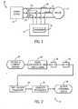
- Fig. 1 is a schematic representation of a motor and controller assembly for a centrifugal pump.
- Fig. 2 is a flow chart generally setting forth the steps of detecting low flow and/or cavitation in a centrifugal pump in accordance with the present invention.
- Fig. 3 is a flow chart setting forth in greater detail that shown in Fig. 2.
- Fig. 4 is a flow chart generally setting forth the steps of detecting low flow and/or cavitation in a centrifugal pump in accordance with another embodiment of the present invention.
- Fig. 5 is a flow chart setting forth in greater detail that shown in Fig. 4.
-
- The present invention is related to the detection of low flow and/or cavitation conditions in a centrifugal pump having a three-phase motor. In Fig. 1 a motor assembly for a centrifugal pump is shown.
Motor assembly 10 includes amotor 12 that receives power from apower supply 14. The assembly also includes acontroller 16 used to monitor as well as control operation of the motor. Thecontroller 16 includes aprocessor 18 that, as will be described in greater detail with respect to Figs. 2-5, implements an algorithm to determine low flow and/or cavitation in the centrifugal pump based on voltage and current data.Motor controller assembly 10 further includes a pair ofvoltage sensors 20 and a pair ofcurrent sensors 22. As is generally known, voltage and current data may be acquired from only two of the phases of a three-phase motor as voltage and current data for the third phase may be extrapolated from the voltage and current data of the monitored two phases. While the present invention will be described with respect to a three-phase motor, the present invention is equivalently applicable to a single-phase motor. - Referring now to Fig. 2, a general overview of detecting and determining the presence of low flow and/or cavitation in a centrifugal pump is shown. The
process 24 employs an FFT to generate a spectrum analysis of a power signal based on voltage and current data acquired from sensors in the pump motor. The process of detecting a low flow and/or cavitation condition in a centrifugal pump using an FFT begins with the acquisition of voltage andcurrent data 26 using voltage and current sensors present in the motor controller assembly. By acquiring the voltage and current data directly from voltage sensors in the motor controller, it is unnecessary to incorporate additional instrumentation to acquire the voltage and current data as the motor controller typically includes voltage and current sensors. Once the voltage and current signals are acquired, the signals are conditioned at 28. Signal conditioning the voltage and current signals includes amplification, buffering, and anti-aliasing of the signals. Once the voltage and current signals are properly conditioned, they are input into an analog-to-digital converter 30 for sampling. From the sampled voltage and current signals, a power signal or calculation is determined at 32. The power signal is determined by multiplying the voltage values and the current values. As a result, a power signal illustrating power in the motor as a function of time may be readily generated. The calculated power signal then undergoes an FFT at 34 to generate a frequency spectrum. By applying an FFT to the power signal, a frequency spectrum can be generated and features of the spectrum compared to those of a baseline frequency spectrum. Based on thiscomparison 36, an output signal signaling either a low flow and/or cavitating condition in the pump may be output at 38. The output may take a number of forms including audio and visual warnings and shut down of the pump. - Referring now to Fig. 3, the specifics of a low flow/cavitation detection scheme utilizing an FIT are shown. The algorithm or
process 40 provides an efficient mechanism to calculate the FFT of motor power and compare spectral energy within a band of frequencies to thresholds established during setup when the pump was known to be operating normally or at or near its best efficiency point. These thresholds or baseline data are acquired during initial setup of the pump motor under a variety of normal operating conditions so that nuances relative to each pump are taken into account when determining the basepoint of operation. Simply, each pump is modeled to determine a baseline data of operation so that variances over time can be readily identified relative to the known healthy and normal operation of the pump. - As previously described, voltage and current data is acquired from voltage and current sensors in the motor starter for the pump motor. Specifically, two line-to-line voltages with respect to a common node and line currents for those two lines of a three-phase induction motor are acquired at 42. The voltage and current data are then input to an anti-aliasing filter at 44 that provides at least 40 dB of attenuation at a frequency that is one-half the sampling rate. It is recommended that the anti-aliasing filter have less than one dB of pass-band ripple. Preferably, the cutoff frequency should be approximately 1 kHz. The anti-aliased signals are then conditioned at 46. The conditioned signals are then input to an analog-to-digital converter and sampled at a sampling rate of approximately 5 kHz. The sampled signals are then input to a power calculation means 50.
- The power calculation is preferably a three-phase calculation done "on the fly". That is, the power of the pump motor is determined in real-time as the data is acquired. The power is determined by treating one of the motor terminals as a common node and then multiplying the line-to-line voltages with respect to that node by the respective line current. Following the power calculation, the power signals are filtered in real-time at 52 and decimated to a 1024 point dataset which is stored in memory to be used by the FFT at 54. Since the power has a relatively large average value relative to the components of interest, the filter output must be allowed to reach this average value before the acquired data is used for FFT calculations. As will be described in greater detail below, a steady state analysis is performed to ensure that the filter output has reached the average value before the data set used for FFT calculations is saved.
- Filtering of the power signal is done at 52 by an eighth order low pass elliptic filter with a cutoff frequency of 90 Hz, pass-band ripple of less than one dB, and attenuation of 60 dB at 180 Hz. This filtering is required to eliminate aliasing when the data is decimated to the final sampling frequency. In order to provide an FFT that would be useful in assessing a variety of diagnostic conditions, the cutoff frequency is chosen to permit sensing signals as high as 120 Hz, or about twice the running frequency of a two-pole motor operating on a 60 Hz line. Preferably, the data originally sampled at approximately 5 kHz is decimated at 54 by a factor of 25 to produce an effective sampling rate of about 213.33 Hz. This choice is based on several factors. For example, the data set for an efficient FFT must be of length to 2n to produce a spectrum with quality definition. Where fault conditions other than cavitation are to be examined, it is also desirable to distinguish between leakage at the power frequency and its harmonics and signals related to the running speed of the motor. For example, for a two-pole motor, these are only separated by the slip frequency. Thus, it is desirable to have at least 0.4 Hz of spectral resolution, defined by:
- Because the power has a large average value compared to the signals of interest, the average value is removed from the data set that is decimated and stored in 54 for use by the FFT process. This eliminates a very large spectral spike at zero frequency as well as to reduce the numerical range that must be dealt with in the FFT procedure thereby permitting the use of fixed point processing.
- Referring again to Fig. 3, the decimated signal then undergoes a 1024 point FFT at 56. Preferably, a digital signal processor is used to apply the FFT and yields results and spectrum values that are the square of the actual amplitude of the signal. Since the square root operation is not trivial, the squared values are used in evaluating the
spectrum 58. Because an FFT for a given data set will show some random variation and spectral amplitude when compared to FFTs from other data sets gathered under conditions that are nominally the same, it is preferable to diminish this randomness by averaging several FFTs together. As a result, preferably, four FFTs are averaged at 60 in accordance with the present invention. Because RAM may often be limited, the result of four separate FFTs prior to computing the average is not stored. That is, the same spectral buckets used to collect results for all four FFTs are used and an average is performed at the end. The average results of the four FFTs are then analyzed to include the spectrum between 5 and 25 Hz. This frequency range has been empirically determined to be the range that noise in an instantaneous power signal increases if pump flow is impeded. The FFT data within the range are then input to a digital-to-analog converter at 62. The resultant signal can then be displayed on an oscilloscope or computer screen for analysis at 64. Additionally, the spectral energy within the band of about 5 to 25 Hz is calculated at 65 and a warning signal oralarm 66 is triggered if the noise energy in this frequency band exceeds a threshold. As such, the noise energy in the frequency band is compared to a baseline signal. - A single FFT could also be implemented rather than averaging four FFTs provided an adequate number of data points are provided to generate a reliable and usable result.
- The frequency spectrum of the real-time power signal and the baseline can be displayed on a console such that an operator or technician can determine a low flow and/or cavitating condition based on visual inspection of the 5-25 Hz frequency range. Other indicators such as warning lights and audio warnings may also be implemented when the acceptable baseline energy for the 5-25Hz range is exceeded on a persistent basis. A two-level warning system may be implemented where a condition that narrowly exceeds the baseline actuates a low priority warning light whereas a condition that is significantly higher than the baseline triggers an urgent alarm.
- As previously described, a steady state analysis is implemented to ensure the integrity of the data acquisition. That is, the data is evaluated for a steady state operating condition by evaluating the average power of the first half of the data set versus that of the second half. For a steady state condition to be present, the average power for the two halves is required to be within one percent of each other. If a non-steady state condition is encountered, the entire FFT data set is discarded and the process starts anew with a new group of four FFTs.
- Referring now to Fig. 4, an alternate algorithm for detecting low flow and/or cavitation in a motor pump utilizes a digital band-pass filter as opposed to an FFT to generate an output that represents only the signal content of the 5 to 25 Hz range of the power signal. Because a filter-based algorithm has less computational burden than an FFT, the filter-based approach is particularly applicable to low cost product implementations. However, if a given motor control product already implements another FFT-based algorithm associated with other control parameters of the motor, the FFT approach may be preferred.
- Similar to the FFT algorithm, the digital band-
pass algorithm 68 begins with the acquisition of voltage andcurrent data 70. The voltage and current data or signals are then conditioned and anti-aliased at 72. The condition signals are then input to an analog-to-digital converter 74 for sampling. Using the sampled signals, a power signal is derived at 76. Similar to the FFT approach, the power signal is derived by multiplying the voltage and current data. The power signal is then input to a digital band-pass filter 78. By first low-pass filtering the motor signal, it is possible to allow for decimation without aliasing. An average of the absolute value of the output of the digital band-pass filter is then determined at 80 and subsequently compared to a series of thresholds at 82. Comparing the averaged absolute value of the filtered real-time power signal to that obtained from the baseline power signal makes it possible to readily determine the presence of anomalies in the pump, i.e. low flow and cavitation. At 84, an operating status of the pump is output. For example, if the pump is operating properly, a "green" or go signal indicative of normal operation may be provided. A "yellow" or cautionary warning could be provided if the onset of low flow or cavitation is detected and a "red" or shutdown warning could be provided if the pump is operating under severe low flow and/or cavitation conditions warranting a shutdown of the pump or urgent requirement to correct operating conditions. - Referring now to Fig. 5, a
process 86 detailing specifically the filter-based algorithm heretofore described is shown. Theprocess 86 begins with the acquisition of voltage andcurrent data 90 and thesubsequent anti-aliasing 92 andsignal conditioning 94 of the voltage and current signals. The conditioned signals are then input to an analog-to-digital converter 96 whereupon a power calculation is implemented at 98 to generate a power signal from the voltage and current signals. Preferably, a three-phase power calculation is made. The power signal is then input to a low-pass filter 100. Preferably, the low-pass filter is a sixth order Chebyshev type-one filter. The low-pass filter signal is then decimated at 102 by a factor of ten resulting in a sampling of 500 Hz. Decimation reduces the pass-band selectivity of the subsequent band-pass filter stage thereby allowing implementation in a 16-bit fixed point digital signal processor architecture. The decimated signal is then input to a sixth order Chebyshev type-one band-pass filter at 104. The band-pass filter stage isolates most frequencies in the 5-15 Hz range (approximate 3 dB pass-band). In one embodiment, the range of interest does not include the 15-30 Hz since the digital band-pass filter must adequately attenuate frequencies above 25 Hz without an overly complex transfer function. At 106, the absolute value of the filter signal is then computed and averaged using a low-pass Butterworth filter 108 with a three dB rolloff at 0.25 Hz. The averaged signal (output of the low-pass filter) is nearly proportional in magnitude to the spectral noise resulting from low flow and/or cavitating operation. The output of the low-pass filter is then input to a digital-to-analog converter at 110 whereupon the signal may be displayed on an oscilloscope or console at 112. Displaying the output of the digital-to-analog converter on an oscilloscope allows an operator or technician to visually view the power signal relative to a baseline signal to determine low flow and/or cavitation in the pump. Other graphical displays could also be used to "display" the signal. For example, a comparison between the real-time signal and a baseline signal could be graphically shown on a computer screen. Additionally, a notification light or audio alarm may be activated 114 based on the differences between the real-time power signal and the baseline signal. Accordingly, the low pass filtered signal is compared to baseline data of the pump operating at or near its last efficiency point. If the differences between the filtered signal and the baseline signal are sufficient, a warning is provided such as activation of a light or alarm. - Therefore, in accordance with one embodiment of the present invention, a motor control for a motor-driven pump is provided. The controller includes at least one voltage sensor and at least one current sensor and is configured to receive a voltage and a current signal of the pump in operation from the at least one voltage sensor and at least one current sensor. The controller is further configured to determine a power signal from the voltage signal and the current signal and generate a real-time spectrum analysis of the power signal. The controller is also configured to determine at least one of a low flow and a cavitation condition in the pump from the spectrum analysis.
- In accordance with another embodiment of the present invention, a computer readable storage medium having stored thereon a computer program to detect and signal improper operation of a motor-driven pump is provided. The computer program represents a set of instructions that when executed by a processor causes the processor to determine a real-time power signal of power in a pump motor assembly. The set of instructions further causes the processor to perform a spectrum analysis on the real-time power signal over several time cycles and generate a real-time frequency spectrum therefrom. The computer program then compares features of the real-time frequency spectrum to those from a baseline frequency spectrum. The computer program then determines differences between the baseline data and that from the real-time frequency spectrum and if the differences exceed a threshold, provides an external notification signaling improper operation in the pump.
- In accordance with yet a further embodiment of the present invention, a method of monitoring proper operation in a centrifugal pump motor includes the step of generating a baseline frequency spectrum of a pump known to be operating properly. The method further includes the step of generating a real-time frequency spectrum of the pump in operation from a power signal derived from voltage and current signals acquired from sensors in a motor of the pump. Portions of the real-time frequency spectrum are then compared to the baseline frequency spectrum and an undesirable pump operating condition is determined therefrom. If an undesirable condition exists, a signal indicating the presence of the condition is provided.
- The present invention has been described in terms of the preferred embodiment, and it is recognized that equivalents, alternatives, and modifications, aside from those expressly stated, are possible and within the scope of the appending claims.
Claims (20)
- A motor controller for a pump (16), the controller (16) configured to:acquire voltage and current signals (26, 42, 70, 90) from at least one voltage sensor (20) and at least one current sensor (22) of a motor starter;determine a power signal (32, 50, 76, 98) in the motor starter from the voltage (20) and current signals (22);perform a spectrum analysis on the power signal (34, 56);compare the analyzed power signal to a base signal (36, 65, 82); andfrom the comparison, determine at least one of low flow and cavitation in the pump.
- The motor controller of claim 1 further configured to perform the spectrum analysis with a fast Fourier transform (34, 56).
- The motor controller of claim 1 further configured to perform the spectrum analysis with band-pass filtering (78, 104).
- The motor controller of claim 1 further configured to detect excessive noise (82, 114) in the power signal as an indication of the at least one of low flow and cavitation.
- The motor controller of claim 1 further configured to model operation of the pump under acceptable operating conditions to determine the base signal (114).
- The motor controller of claim 1 further configured to perform the spectrum analysis over several cycles and compare the analyzed power signal over several cycles to determine the at least one of low flow and cavitation in the pump.
- A computer readable storage medium having stored thereon a computer program to determine improper operation of a pump and representing a set of instructions that when executed by a processor (18) causes the processor (18) to:determine a real-time power signal (32, 50, 76, 98) of power in a pump motor assembly;perform a spectrum analysis on the real-time power signal over several time cycles and generate a real-time signal frequency spectrum therefrom (34, 56);compare the real-time frequency spectrum to a baseline frequency spectrum (36, 65, 82, 114);determine differences between the baseline frequency spectrum and the real-time frequency spectrum in a frequency range of interest; andif the differences exceed a threshold, output a notification signal (38, 66, 84, 114).
- The computer readable storage medium of claim 7 wherein the set of instructions further causes the computer to activate a warning light if the differences exceed the threshold (64, 66, 112, 114).
- The computer readable storage medium of claim 7 wherein the set of instructions further causes the processor to apply a fast Fourier transform (34, 56) on the real-time power signal to generate the real-time frequency spectrum.
- The computer readable storage medium of claim 7 wherein the set of instructions further causes the processor to input the real-time power signal to a band pass filter (78, 104) to extract the real-time frequency spectrum in the frequency range of interest.
- The computer readable storage medium of claim 7 wherein the set of instructions further causes the processor to determine one of low flow and cavitation in the pump based on spectral energy differences between the real-time power signal and a baseline power signal (114).
- The computer readable storage medium of claim 11 wherein the set of instructions further causes the processor to limit the comparison to spectral energy differences in the 5-25 Hz range.
- The computer readable storage medium of claim 7 wherein the set of instructions causes the processor to determine the real-time power signal (32, 50, 76, 98) from voltage and current signals (26, 42, 70, 90) acquired from at least two phases of a three-phase motor.
- The computer readable storage medium of claim 7 wherein the differences indicate undesirable noise in the real-time power signal.
- A method of monitoring proper operation of a centrifugal pump comprising the steps of:generating a baseline frequency spectrum of a pump known to be operating properly;generating a real-time frequency spectrum of the pump in operation from a power signal (32, 50, 76, 98) derived from voltage and current signals (26, 42, 70, 90) acquired from sensors in a motor of the pump (20, 22);comparing the real-time frequency spectrum and the baseline frequency spectrum and determining any undesirable pump operating condition therefrom (36, 114); andsignaling presence of the undesirable pump operating condition (66, 114).
- The method of claim 15 wherein the step of generating the real-time frequency spectrum includes the steps of acquiring voltage and current signals (26, 42, 70, 90) from at least two phases from the motor and anti-aliasing the acquired signals.
- The method of claim 16 wherein the step of generating the real-time frequency spectrum includes the step of applying a fast Fourier transform (34, 56) to the power signal.
- The method of claim 16 wherein the step of generating the real-time frequency spectrum includes the step of band pass filtering the power signal (78, 104).
- The method of claim 16 further comprising the steps of generating the real-time frequency spectrum over several time periods, determining an average of the several time periods, and comparing the average to the baseline frequency spectrum.
- The method of claim 16 wherein noise within a selected frequency band of the real-time frequency spectrum exceeding a threshold (82) is indicative of the undesirable pump operating condition.
Applications Claiming Priority (2)
| Application Number | Priority Date | Filing Date | Title |
|---|---|---|---|
| US65734 | 1987-06-24 | ||
| US10/065,734 US6709240B1 (en) | 2002-11-13 | 2002-11-13 | Method and apparatus of detecting low flow/cavitation in a centrifugal pump |
Publications (2)
| Publication Number | Publication Date |
|---|---|
| EP1420165A2 true EP1420165A2 (en) | 2004-05-19 |
| EP1420165A3 EP1420165A3 (en) | 2006-01-04 |
Family
ID=31975664
Family Applications (1)
| Application Number | Title | Priority Date | Filing Date |
|---|---|---|---|
| EP20030025234 Withdrawn EP1420165A3 (en) | 2002-11-13 | 2003-11-05 | Method and apparatus of detecting the condition of a centrifugal pump |
Country Status (3)
| Country | Link |
|---|---|
| US (1) | US6709240B1 (en) |
| EP (1) | EP1420165A3 (en) |
| CN (1) | CN100575935C (en) |
Cited By (2)
| Publication number | Priority date | Publication date | Assignee | Title |
|---|---|---|---|---|
| CN108457912A (en) * | 2018-03-02 | 2018-08-28 | 大连理工大学 | A kind of effective fluidic device and design method for inhibiting blade surface cavitation |
| EP3276439B1 (en) | 2016-07-29 | 2021-12-01 | Raytheon Technologies Corporation | System and method for assessing the health of a first apparatus by monitoring a dependent second apparatus |
Families Citing this family (82)
| Publication number | Priority date | Publication date | Assignee | Title |
|---|---|---|---|---|
| US20030210007A1 (en) * | 2002-05-08 | 2003-11-13 | Chia-Chang Hsu | Input power control device |
| US6933693B2 (en) * | 2002-11-08 | 2005-08-23 | Eaton Corporation | Method and apparatus of detecting disturbances in a centrifugal pump |
| US6941785B2 (en) * | 2003-05-13 | 2005-09-13 | Ut-Battelle, Llc | Electric fuel pump condition monitor system using electrical signature analysis |
| US8540493B2 (en) * | 2003-12-08 | 2013-09-24 | Sta-Rite Industries, Llc | Pump control system and method |
| US20110002792A1 (en) * | 2004-04-09 | 2011-01-06 | Bartos Ronald P | Controller for a motor and a method of controlling the motor |
| US8177520B2 (en) * | 2004-04-09 | 2012-05-15 | Regal Beloit Epc Inc. | Controller for a motor and a method of controlling the motor |
| US8133034B2 (en) * | 2004-04-09 | 2012-03-13 | Regal Beloit Epc Inc. | Controller for a motor and a method of controlling the motor |
| US7873486B2 (en) * | 2004-07-29 | 2011-01-18 | Tektronix, Inc. | Spectrogram mask trigger |
| US8019479B2 (en) | 2004-08-26 | 2011-09-13 | Pentair Water Pool And Spa, Inc. | Control algorithm of variable speed pumping system |
| US7874808B2 (en) | 2004-08-26 | 2011-01-25 | Pentair Water Pool And Spa, Inc. | Variable speed pumping system and method |
| US7845913B2 (en) | 2004-08-26 | 2010-12-07 | Pentair Water Pool And Spa, Inc. | Flow control |
| US8480373B2 (en) * | 2004-08-26 | 2013-07-09 | Pentair Water Pool And Spa, Inc. | Filter loading |
| US8602745B2 (en) | 2004-08-26 | 2013-12-10 | Pentair Water Pool And Spa, Inc. | Anti-entrapment and anti-dead head function |
| US7686589B2 (en) | 2004-08-26 | 2010-03-30 | Pentair Water Pool And Spa, Inc. | Pumping system with power optimization |
| US7854597B2 (en) | 2004-08-26 | 2010-12-21 | Pentair Water Pool And Spa, Inc. | Pumping system with two way communication |
| US8469675B2 (en) | 2004-08-26 | 2013-06-25 | Pentair Water Pool And Spa, Inc. | Priming protection |
| US8281425B2 (en) | 2004-11-01 | 2012-10-09 | Cohen Joseph D | Load sensor safety vacuum release system |
| US7637723B2 (en) * | 2005-07-25 | 2009-12-29 | Emerson Electric Co | Cavitation detection device and method |
| US7298129B2 (en) * | 2005-11-04 | 2007-11-20 | Tektronix, Inc. | Time arbitrary signal power statistics measurement device and method |
| US20070177990A1 (en) * | 2006-01-27 | 2007-08-02 | Applied Drives & Systems, Inc. | Centrifugal pump casing relief system |
| DE102006016164A1 (en) * | 2006-04-06 | 2007-10-11 | GM Global Technology Operations, Inc., Detroit | Wind-shield washing assembly for motor vehicle, switches off washing process with change in electrical parameter of feed-pump |
| US8297937B2 (en) * | 2006-06-12 | 2012-10-30 | Stak Enterprises, Inc. | Pump control apparatus, system and method |
| US20080095638A1 (en) * | 2006-10-13 | 2008-04-24 | A.O. Smith Corporation | Controller for a motor and a method of controlling the motor |
| US7690897B2 (en) * | 2006-10-13 | 2010-04-06 | A.O. Smith Corporation | Controller for a motor and a method of controlling the motor |
| EP2039939B2 (en) * | 2007-09-20 | 2020-11-18 | Grundfos Management A/S | Method for monitoring an energy conversion device |
| DE102008030544B4 (en) * | 2008-06-27 | 2014-05-22 | Siemens Aktiengesellschaft | Model-based method for monitoring micromechanical pumps |
| US8354809B2 (en) | 2008-10-01 | 2013-01-15 | Regal Beloit Epc Inc. | Controller for a motor and a method of controlling the motor |
| MX2011003708A (en) | 2008-10-06 | 2011-06-16 | Pentair Water Pool & Spa Inc | Method of operating a safety vacuum release system. |
| CN101520391B (en) * | 2009-04-01 | 2011-01-05 | 奇瑞汽车股份有限公司 | Bench cavitation test method for engine cooling system |
| US8564233B2 (en) | 2009-06-09 | 2013-10-22 | Sta-Rite Industries, Llc | Safety system and method for pump and motor |
| US9556874B2 (en) | 2009-06-09 | 2017-01-31 | Pentair Flow Technologies, Llc | Method of controlling a pump and motor |
| US8436559B2 (en) | 2009-06-09 | 2013-05-07 | Sta-Rite Industries, Llc | System and method for motor drive control pad and drive terminals |
| EP2526299A1 (en) * | 2010-02-25 | 2012-11-28 | Hayward Industries, Inc. | Pump controller with external device control capability |
| WO2011106530A1 (en) | 2010-02-25 | 2011-09-01 | Hayward Industries, Inc. | Universal mount for a variable speed pump drive user interface |
| US9777748B2 (en) * | 2010-04-05 | 2017-10-03 | Eaton Corporation | System and method of detecting cavitation in pumps |
| DE102010028557B4 (en) | 2010-05-04 | 2024-05-08 | BSH Hausgeräte GmbH | Dishwasher with a concentricity monitoring unit |
| TW201217010A (en) | 2010-06-22 | 2012-05-01 | Thoratec Corp | Apparatus and method for modifying pressure-flow characteristics of a pump |
| EP2585129B8 (en) | 2010-06-22 | 2017-07-12 | Tc1 Llc | Fluid delivery system and method for monitoring fluid delivery system |
| CA2820887C (en) | 2010-12-08 | 2019-10-22 | Pentair Water Pool And Spa, Inc. | Discharge vacuum relief valve for safety vacuum release system |
| EP2500579A1 (en) * | 2011-03-17 | 2012-09-19 | Siemens Aktiengesellschaft | Detection of cavitation and gas entrainment in an electric rotary pump |
| JP5776447B2 (en) | 2011-08-30 | 2015-09-09 | セイコーエプソン株式会社 | Control device and excision device used in connection with fluid ejection device for excising biological tissue by ejected fluid |
| US9243619B2 (en) * | 2011-09-13 | 2016-01-26 | Seiko Epson Corporation | Liquid feed pump and circulation pump with detection units to detect operating states of the pumps |
| US10465676B2 (en) | 2011-11-01 | 2019-11-05 | Pentair Water Pool And Spa, Inc. | Flow locking system and method |
| CN104170244B (en) | 2011-12-13 | 2018-01-09 | 沙特阿拉伯石油公司 | Submersible electric pump monitors and failure predication |
| EP2618002B1 (en) * | 2012-01-17 | 2016-05-04 | ABB Technology Oy | Method for detecting the correct rotational direction of a centrifugal apparatus, and a centrifugal apparatus assembly |
| US8798825B1 (en) | 2012-07-06 | 2014-08-05 | Richard L. Hartman | Wakeboat hull control systems and methods |
| US9255578B2 (en) * | 2012-07-31 | 2016-02-09 | Fisher-Rosemount Systems, Inc. | Systems and methods to monitor pump cavitation |
| US9885360B2 (en) | 2012-10-25 | 2018-02-06 | Pentair Flow Technologies, Llc | Battery backup sump pump systems and methods |
| US9846184B2 (en) * | 2012-11-20 | 2017-12-19 | Tektronix, Inc. | Combinatorial mask triggering in time or frequency domain |
| DE102014100945A1 (en) * | 2014-01-28 | 2015-07-30 | Khs Gmbh | Device and method for error detection in machines |
| US10161988B2 (en) | 2014-05-14 | 2018-12-25 | General Electric Company | Methods and systems for monitoring a fluid lifting device |
| GB2536461A (en) * | 2015-03-18 | 2016-09-21 | Edwards Ltd | Pump monitoring apparatus and method |
| GB2541682B (en) | 2015-08-25 | 2017-09-06 | Airbus Operations Ltd | Pump health monitoring |
| US10134257B2 (en) * | 2016-08-05 | 2018-11-20 | Caterpillar Inc. | Cavitation limiting strategies for pumping system |
| US11505289B2 (en) | 2016-09-09 | 2022-11-22 | Richard L. Hartman | Wakeboat bilge measurement assemblies and methods |
| US10829186B2 (en) | 2016-09-09 | 2020-11-10 | Richard L. Hartman | Wakeboat ballast measurement assemblies and methods |
| US11014634B2 (en) | 2016-09-09 | 2021-05-25 | Richard L. Hartman | Hydraulic power sources for watercraft and methods for providing hydraulic power aboard a watercraft |
| US10227113B2 (en) | 2016-09-09 | 2019-03-12 | Richard L. Hartman | Wakeboat engine powered ballasting apparatus and methods |
| US11254395B2 (en) | 2016-09-09 | 2022-02-22 | Richard L. Hartman | Aquatic invasive species control apparatuses and methods for watercraft |
| US11014635B2 (en) | 2016-09-09 | 2021-05-25 | Richard L. Hartman | Power source assemblies and methods for distributing power aboard a watercraft |
| US10329004B2 (en) | 2016-09-09 | 2019-06-25 | Richard L. Hartman | Wakeboat ballast measurement assemblies and methods |
| US10611439B2 (en) | 2016-09-09 | 2020-04-07 | Richard L. Hartman | Wakeboat engine hydraulic pump mounting apparatus and methods |
| US10435122B2 (en) | 2016-09-09 | 2019-10-08 | Richard L. Hartman | Wakeboat propulsion apparatuses and methods |
| US12600441B2 (en) | 2016-09-09 | 2026-04-14 | Richard L. Hartman | Thruster conduit assemblies |
| US10864971B2 (en) | 2016-09-09 | 2020-12-15 | Richard L. Hartman | Wakeboat hydraulic manifold assemblies and methods |
| US10611440B2 (en) | 2016-09-09 | 2020-04-07 | Richard L. Hartman | Boat propulsion assemblies and methods |
| US10718337B2 (en) | 2016-09-22 | 2020-07-21 | Hayward Industries, Inc. | Self-priming dedicated water feature pump |
| DE102017004097A1 (en) * | 2017-04-28 | 2018-10-31 | Wilo Se | Method for detecting an abnormal operating state of a pump set |
| CN108105080B (en) * | 2017-12-08 | 2019-06-07 | 重庆气体压缩机厂有限责任公司 | For the detection method of cavitation, device, storage medium and processor |
| CA2991725A1 (en) * | 2018-01-10 | 2019-07-10 | Psi Technologies Inc. | Method and apparatus to predict failure and control vibrations in a subsurface artificial lift system |
| CN110261669A (en) * | 2019-07-12 | 2019-09-20 | 四川虹美智能科技有限公司 | Detection plate, frequency-changeable compressor intelligent management system and operational parameter detection method |
| CN110410336B (en) * | 2019-07-22 | 2021-02-02 | 西安因联信息科技有限公司 | Automatic pump cavitation state identification method |
| US11852148B2 (en) * | 2019-10-29 | 2023-12-26 | Gpm, Inc. | Real-time pump monitoring with prescriptive analytics |
| CN114263621B (en) * | 2021-11-26 | 2023-07-21 | 江苏科技大学 | A test method and system for cavitation fault diagnosis simulation of centrifugal pump |
| CN114922827A (en) * | 2022-04-08 | 2022-08-19 | 宁波兰宁石化科技有限公司 | A real-time monitoring method of centrifugal pump cavitation |
| US20240068910A1 (en) * | 2022-07-12 | 2024-02-29 | Cattron North America, Inc. | Cavitation Detection Using Torque Load and/or Instantaneous Fuel Consumption |
| CA3219433A1 (en) * | 2022-11-18 | 2024-05-18 | Cattron North America, Inc. | Cavitation detection using torque load and/or instantaneous fuel consumption |
| US12606279B2 (en) | 2022-12-22 | 2026-04-21 | Skier's Choice | Wakeboat hull control systems and methods |
| CN116432527B (en) * | 2023-04-07 | 2024-10-18 | 中国长江三峡集团有限公司 | Cavitation prediction method and device, storage medium and electronic equipment |
| CN117072416A (en) * | 2023-07-20 | 2023-11-17 | 上海中韩杜科泵业制造有限公司 | Pressure detection system and pressure detection method |
| EP4513208A1 (en) * | 2023-08-24 | 2025-02-26 | GE Energy Power Conversion Technology Limited | Method and system of evaluating and controlling a rotating electrical machine |
| CN120969206B (en) * | 2025-09-28 | 2026-08-07 | 湖南湘祥泵业制造有限公司 | Online Detection Device and Method for Water Pump Flow Rate and Head Using Acoustic Emission Technology |
Citations (1)
| Publication number | Priority date | Publication date | Assignee | Title |
|---|---|---|---|---|
| US3839628A (en) * | 1972-08-09 | 1974-10-01 | R Ramachandran | Method and apparatus analyzing and monitoring the performance and operation of machines and processes driven by electrical motors |
Family Cites Families (18)
| Publication number | Priority date | Publication date | Assignee | Title |
|---|---|---|---|---|
| US4123009A (en) * | 1974-05-14 | 1978-10-31 | The International Nickel Company, Inc. | Load sensor for a grinding mill |
| US4473338A (en) * | 1980-09-15 | 1984-09-25 | Garmong Victor H | Controlled well pump and method of analyzing well production |
| DE3725754A1 (en) * | 1987-08-04 | 1989-02-16 | Busch Dieter & Co Prueftech | DEVICE FOR MONITORING PUMPS FOR HAZARDOUS CAVITATION |
| JPH0737791B2 (en) * | 1988-11-28 | 1995-04-26 | 株式会社日立製作所 | Pump backflow detection device, pump operation control device for pumping equipment, and variable-speed pumped storage power generation / electric device |
| US5015151A (en) * | 1989-08-21 | 1991-05-14 | Shell Oil Company | Motor controller for electrical submersible pumps |
| US5754450A (en) * | 1993-09-06 | 1998-05-19 | Diagnostics Temed Ltd. | Detection of faults in the working of electric motor driven equipment |
| US5767780A (en) * | 1993-09-22 | 1998-06-16 | Lockheed Martin Energy Research Corporation | Detector for flow abnormalities in gaseous diffusion plant compressors |
| US5479824A (en) * | 1993-12-21 | 1996-01-02 | General Electric Company | On-line shaft crack detector |
| US5671635A (en) * | 1994-11-14 | 1997-09-30 | Westinghouse Electric Corporation | Method and apparatus for monitoring of spring pack displacement of a motor-operated valve |
| US6144924A (en) * | 1996-05-20 | 2000-11-07 | Crane Nuclear, Inc. | Motor condition and performance analyzer |
| US5833437A (en) * | 1996-07-02 | 1998-11-10 | Shurflo Pump Manufacturing Co. | Bilge pump |
| US6240372B1 (en) * | 1997-11-14 | 2001-05-29 | Arch Development Corporation | System for surveillance of spectral signals |
| US6260004B1 (en) * | 1997-12-31 | 2001-07-10 | Innovation Management Group, Inc. | Method and apparatus for diagnosing a pump system |
| US6041163A (en) * | 1998-04-23 | 2000-03-21 | Daewoo Heavy Industries Ltd. | Apparatus for controlling a pump motor of a forklift truck |
| US6366862B1 (en) * | 2000-04-19 | 2002-04-02 | National Instruments Corporation | System and method for analyzing signals generated by rotating machines |
| US6954713B2 (en) * | 2001-03-01 | 2005-10-11 | Fisher-Rosemount Systems, Inc. | Cavitation detection in a process plant |
| US6532433B2 (en) * | 2001-04-17 | 2003-03-11 | General Electric Company | Method and apparatus for continuous prediction, monitoring and control of compressor health via detection of precursors to rotating stall and surge |
| US6659815B2 (en) * | 2001-06-11 | 2003-12-09 | Maruta Electric Boatworks Llc | Efficient motors and controls for watercraft |
-
2002
- 2002-11-13 US US10/065,734 patent/US6709240B1/en not_active Expired - Fee Related
-
2003
- 2003-11-05 EP EP20030025234 patent/EP1420165A3/en not_active Withdrawn
- 2003-11-12 CN CN200310103836A patent/CN100575935C/en not_active Expired - Fee Related
Patent Citations (1)
| Publication number | Priority date | Publication date | Assignee | Title |
|---|---|---|---|---|
| US3839628A (en) * | 1972-08-09 | 1974-10-01 | R Ramachandran | Method and apparatus analyzing and monitoring the performance and operation of machines and processes driven by electrical motors |
Cited By (4)
| Publication number | Priority date | Publication date | Assignee | Title |
|---|---|---|---|---|
| EP3276439B1 (en) | 2016-07-29 | 2021-12-01 | Raytheon Technologies Corporation | System and method for assessing the health of a first apparatus by monitoring a dependent second apparatus |
| EP3276439B2 (en) † | 2016-07-29 | 2025-03-26 | RTX Corporation | System and method for assessing the health of a first apparatus by monitoring a dependent second apparatus |
| CN108457912A (en) * | 2018-03-02 | 2018-08-28 | 大连理工大学 | A kind of effective fluidic device and design method for inhibiting blade surface cavitation |
| CN108457912B (en) * | 2018-03-02 | 2019-11-08 | 大连理工大学 | A jet device and design method for effectively suppressing cavitation on blade surface |
Also Published As
| Publication number | Publication date |
|---|---|
| EP1420165A3 (en) | 2006-01-04 |
| US6709240B1 (en) | 2004-03-23 |
| CN100575935C (en) | 2009-12-30 |
| CN1501077A (en) | 2004-06-02 |
Similar Documents
| Publication | Publication Date | Title |
|---|---|---|
| US6709240B1 (en) | Method and apparatus of detecting low flow/cavitation in a centrifugal pump | |
| US6933693B2 (en) | Method and apparatus of detecting disturbances in a centrifugal pump | |
| EP2556257B1 (en) | System and method of detecting cavitation in pumps | |
| EP2374015B1 (en) | System and method for motor fault detection using stator current noise cancellation | |
| EP2455772A2 (en) | System and method for bearing fault detection using stator current noise cancellation | |
| JP7198089B2 (en) | POWER CONVERTER, ROTATING MACHINE SYSTEM, AND DIAGNOSTIC METHOD | |
| DE102009026128A1 (en) | System and method for detecting stall and surge | |
| WO2008085535A2 (en) | Turbine engine stall warning system and method | |
| CN106772049A (en) | Generator's motor shaft insulating monitoring and positioner and method | |
| Perovic et al. | Fuzzy logic system to detect pump faults from motor current spectra | |
| CN206618839U (en) | Generator's motor shaft insulating monitoring and positioner | |
| CN108169559B (en) | Method for judging abnormality of motor stator current spectrum analysis equipment | |
| Wang et al. | Some new signal processing approaches for gear fault diagnosis | |
| JP2014066209A (en) | Compressor, and method of controlling operation of compressor | |
| CN107436244B (en) | Equipment fault alarm method based on frequency segmentation vibration data acquisition | |
| CN103206387B (en) | For detecting method and the centrifugation apparatus assembly in the correct rotation direction of centrifugation apparatus | |
| CN112557753A (en) | Online detection method for low-frequency oscillation of Hanning self-convolution window in frequency division band | |
| JPH0747963B2 (en) | How to diagnose hydraulic circuit | |
| CN113219374A (en) | Transformer voltage fault detection method | |
| WO2018114074A1 (en) | Turbocompressor device | |
| RU2172433C1 (en) | Method of and system for diagnosing stalling and surging of turbocompressor | |
| EP4513208A1 (en) | Method and system of evaluating and controlling a rotating electrical machine | |
| KR20260055619A (en) | Rotating machine diagnosis device through removal of electronic vibration components | |
| CN121740218A (en) | Rotary machine vibration frequency domain detector based on singlechip | |
| Belsak et al. | Diagnostics Cracks in Gears with Wavelet Analysis |
Legal Events
| Date | Code | Title | Description |
|---|---|---|---|
| PUAI | Public reference made under article 153(3) epc to a published international application that has entered the european phase |
Free format text: ORIGINAL CODE: 0009012 |
|
| AK | Designated contracting states |
Kind code of ref document: A2 Designated state(s): AT BE BG CH CY CZ DE DK EE ES FI FR GB GR HU IE IT LI LU MC NL PT RO SE SI SK TR |
|
| AX | Request for extension of the european patent |
Extension state: AL LT LV MK |
|
| PUAL | Search report despatched |
Free format text: ORIGINAL CODE: 0009013 |
|
| AK | Designated contracting states |
Kind code of ref document: A3 Designated state(s): AT BE BG CH CY CZ DE DK EE ES FI FR GB GR HU IE IT LI LU MC NL PT RO SE SI SK TR |
|
| AX | Request for extension of the european patent |
Extension state: AL LT LV MK |
|
| 17P | Request for examination filed |
Effective date: 20060331 |
|
| AKX | Designation fees paid |
Designated state(s): AT BE BG CH CY CZ DE DK EE ES FI FR GB GR HU IE IT LI LU MC NL PT RO SE SI SK TR |
|
| 17Q | First examination report despatched |
Effective date: 20101116 |
|
| R17C | First examination report despatched (corrected) |
Effective date: 20101123 |
|
| GRAP | Despatch of communication of intention to grant a patent |
Free format text: ORIGINAL CODE: EPIDOSNIGR1 |
|
| INTG | Intention to grant announced |
Effective date: 20150417 |
|
| STAA | Information on the status of an ep patent application or granted ep patent |
Free format text: STATUS: THE APPLICATION IS DEEMED TO BE WITHDRAWN |
|
| 18D | Application deemed to be withdrawn |
Effective date: 20150828 |