EP1420160A2 - Air intake arrangement for an internal combustion engine - Google Patents
Air intake arrangement for an internal combustion engine Download PDFInfo
- Publication number
- EP1420160A2 EP1420160A2 EP03103352A EP03103352A EP1420160A2 EP 1420160 A2 EP1420160 A2 EP 1420160A2 EP 03103352 A EP03103352 A EP 03103352A EP 03103352 A EP03103352 A EP 03103352A EP 1420160 A2 EP1420160 A2 EP 1420160A2
- Authority
- EP
- European Patent Office
- Prior art keywords
- air collector
- intake system
- intake manifold
- intake
- air
- Prior art date
- Legal status (The legal status is an assumption and is not a legal conclusion. Google has not performed a legal analysis and makes no representation as to the accuracy of the status listed.)
- Granted
Links
Images
Classifications
-
- F—MECHANICAL ENGINEERING; LIGHTING; HEATING; WEAPONS; BLASTING
- F02—COMBUSTION ENGINES; HOT-GAS OR COMBUSTION-PRODUCT ENGINE PLANTS
- F02M—SUPPLYING COMBUSTION ENGINES IN GENERAL WITH COMBUSTIBLE MIXTURES OR CONSTITUENTS THEREOF
- F02M35/00—Combustion-air cleaners, air intakes, intake silencers, or induction systems specially adapted for, or arranged on, internal-combustion engines
- F02M35/10—Air intakes; Induction systems
- F02M35/104—Intake manifolds
- F02M35/112—Intake manifolds for engines with cylinders all in one line
-
- F—MECHANICAL ENGINEERING; LIGHTING; HEATING; WEAPONS; BLASTING
- F02—COMBUSTION ENGINES; HOT-GAS OR COMBUSTION-PRODUCT ENGINE PLANTS
- F02M—SUPPLYING COMBUSTION ENGINES IN GENERAL WITH COMBUSTIBLE MIXTURES OR CONSTITUENTS THEREOF
- F02M35/00—Combustion-air cleaners, air intakes, intake silencers, or induction systems specially adapted for, or arranged on, internal-combustion engines
- F02M35/10—Air intakes; Induction systems
- F02M35/10006—Air intakes; Induction systems characterised by the position of elements of the air intake system in direction of the air intake flow, i.e. between ambient air inlet and supply to the combustion chamber
- F02M35/10026—Plenum chambers
- F02M35/10039—Intake ducts situated partly within or on the plenum chamber housing
-
- F—MECHANICAL ENGINEERING; LIGHTING; HEATING; WEAPONS; BLASTING
- F02—COMBUSTION ENGINES; HOT-GAS OR COMBUSTION-PRODUCT ENGINE PLANTS
- F02M—SUPPLYING COMBUSTION ENGINES IN GENERAL WITH COMBUSTIBLE MIXTURES OR CONSTITUENTS THEREOF
- F02M35/00—Combustion-air cleaners, air intakes, intake silencers, or induction systems specially adapted for, or arranged on, internal-combustion engines
- F02M35/10—Air intakes; Induction systems
- F02M35/10209—Fluid connections to the air intake system; their arrangement of pipes, valves or the like
- F02M35/10216—Fuel injectors; Fuel pipes or rails; Fuel pumps or pressure regulators
-
- F—MECHANICAL ENGINEERING; LIGHTING; HEATING; WEAPONS; BLASTING
- F02—COMBUSTION ENGINES; HOT-GAS OR COMBUSTION-PRODUCT ENGINE PLANTS
- F02M—SUPPLYING COMBUSTION ENGINES IN GENERAL WITH COMBUSTIBLE MIXTURES OR CONSTITUENTS THEREOF
- F02M35/00—Combustion-air cleaners, air intakes, intake silencers, or induction systems specially adapted for, or arranged on, internal-combustion engines
- F02M35/10—Air intakes; Induction systems
- F02M35/10242—Devices or means connected to or integrated into air intakes; Air intakes combined with other engine or vehicle parts
- F02M35/10301—Flexible, resilient, pivotally or movable parts; Membranes
-
- F—MECHANICAL ENGINEERING; LIGHTING; HEATING; WEAPONS; BLASTING
- F02—COMBUSTION ENGINES; HOT-GAS OR COMBUSTION-PRODUCT ENGINE PLANTS
- F02M—SUPPLYING COMBUSTION ENGINES IN GENERAL WITH COMBUSTIBLE MIXTURES OR CONSTITUENTS THEREOF
- F02M35/00—Combustion-air cleaners, air intakes, intake silencers, or induction systems specially adapted for, or arranged on, internal-combustion engines
- F02M35/10—Air intakes; Induction systems
- F02M35/10314—Materials for intake systems
- F02M35/10321—Plastics; Composites; Rubbers
-
- F—MECHANICAL ENGINEERING; LIGHTING; HEATING; WEAPONS; BLASTING
- F02—COMBUSTION ENGINES; HOT-GAS OR COMBUSTION-PRODUCT ENGINE PLANTS
- F02M—SUPPLYING COMBUSTION ENGINES IN GENERAL WITH COMBUSTIBLE MIXTURES OR CONSTITUENTS THEREOF
- F02M35/00—Combustion-air cleaners, air intakes, intake silencers, or induction systems specially adapted for, or arranged on, internal-combustion engines
- F02M35/10—Air intakes; Induction systems
- F02M35/1034—Manufacturing and assembling intake systems
- F02M35/10354—Joining multiple sections together
Definitions
- the invention relates to an intake system for an internal combustion engine according to the preamble of claim 1.
- each intake pipe is made up of three parts, a first intake manifold part on the cylinder head side and a second intake pipe part, which is connected to the air collector is, are each longitudinally divided and by a middle one The intake manifold part can be complemented.
- This middle one The intake manifold part is interchangeable, with one change the intake manifold geometry of this part different overall lengths of the suction pipe can be adjusted. hereby is an intake manifold length adjustment with relatively simple measures while maintaining the air collector geometry to different Internal combustion engines possible.
- the invention lies Problem based on creating a compact intake system, which with little effort to different internal combustion engines can be customized.
- the intake pipe is longitudinally divided, so that at least two along a longitudinal pipe plane Intake pipe parts are formed, the air collector with a the intake manifold parts a coherent, one-piece base part forms and the other intake manifold part as an interchangeable part is executed, which forms a wall shell of the air collector.
- the base part can be identical for different engine variants be made, whereas the interchangeable part to the respective Requirements especially with regard to the motor size and - performance data can be adjusted. Because of the one-piece Execution of a suction pipe part with a wall section of the Air collector is a particularly compact size.
- suction pipe and wall part of the air collector can in particular also be formed in one piece and for example by injection molding manufactured as a common plastic component become.
- an interchangeable intake manifold part with modified geometry different intake manifold lengths or Intake manifold volumes can be realized that match the respective internal combustion engine are adjusted.
- the remaining intake manifold parts and the remaining wall sections of the air collector - the base part - can are retained unchanged, which on the one hand means the variety of parts and thus the tool costs are reduced and on the other hand also the design and size of the intake system in the Mainly be maintained.
- the intake manifold part forming the interchangeable part can for example by welding firmly and indissolubly to the Base part to be connected. However, there may also be one detachable connection into consideration.
- a pipe end piece protrudes of the interchangeable intake manifold part into the interior of the air collector.
- the length of this protruding intake manifold, which is part of the interchangeable intake manifold part forms, determines the total length of the intake manifold. Therefore it is generally sufficient to use different intake manifold parts long pipe end piece to form the total length of the To vary intake manifold and to different internal combustion engines adapt.
- the pipe end fitting protruding into the air collector requires no additional space, which makes it special compact design can be achieved.
- a radially projecting stop can be provided on the pipe end connector be in the installed position on the inside wall of the Air collector supports, which on the one hand facilitates assembly is given and on the other hand an airtight seal between the interchangeable intake manifold part and the air collector is supported. Between the stop and the inner wall of the Air collector, a sealing element can be arranged.
- the exchangeable intake manifold part expediently forms an upper shell of the suction pipe and the wall part connected to it a cover shell of the air collector.
- the lower shell of the suction tube interchangeable, with in In this case, only one wall side of the air collector is expediently in one piece with the lower shell.
- the intake system 1 shown in FIG. 1 for an internal combustion engine comprises an air collector 2 and several, from the air collector 2 branching suction pipes 3, of which, however, in Fig. 1 only one is shown in section, with the suction pipes too led and over the cylinder inlets of the internal combustion engine to attach a flange 10 to the cylinder head of the internal combustion engine are.
- Both the air collector 2 and each suction pipe 3 are formed in two parts.
- Each suction pipe 3 is divided lengthways and consists of two intake manifold parts 4 and 5, one of which the upper intake manifold part 4 an exchangeable upper shell and that lower suction tube part 5 forms a fixed lower shell.
- the air collector 2 consists of a box 6 and an interchangeable one Lid shell 7.
- the lid shell 7 forms with the upper, exchangeable or insertable intake manifold part 4 a common one-piece component.
- Box 6 of the air collector 2 forms with the lower intake manifold part 5 - the lower shell of the Intake pipe 3 - also a one-piece component.
- plenum and intake manifold are useful as a plastic injection molded component manufactured, the lid shell 7 of the air collector 2 with the upper intake manifold part 4 is a common injection molded part and in accordingly the box 6 of the air collector with the lower one Intake pipe part 5 forms a common injection molded part.
- the lid shell 7 and that related to the lid shell upper suction tube part 4 are detachable and replaceable and can with fasteners 11 and 12 with the box 6 and the lower intake manifold part 5 are connected.
- Upper and lower intake manifold part can also be inseparable from each other are connected, for example by welding.
- a Rohrendstutzen 8 formed, which in the assembled position in protrudes the interior of the air collector 2 and open to it Expanded like a trumpet.
- This pipe end connector 8 is designed as a continuous circumferential tube, whereas the section outside the air collector the upper intake manifold part 4 designed as a half-shell is complementary in the assembled position of the lower intake manifold part 5 is supplemented to a common intake manifold.
- the total length by varying the length of the pipe end connector 8 of the suction pipe 3 can be varied, the other The geometry of the intake system can be retained unchanged can. If necessary, it can also be useful, alternatively or additionally the geometry of the lid shell 7 of the Air collector 2 to vary, also to change the Suction pipe length and / or the air volume in the air collector and to reach the intake manifold; this case is also in the figures shown, in which the lid shell geometry differs.
- At the pipe end piece 8 is a one-piece, radially over the outer wall stop 9 protruding from the pipe end fitting, which is installed on the inside wall of the air collector box 2 is present.
- the stop 9 makes installation easier represents.
Landscapes
- Engineering & Computer Science (AREA)
- Chemical & Material Sciences (AREA)
- Combustion & Propulsion (AREA)
- Mechanical Engineering (AREA)
- General Engineering & Computer Science (AREA)
- Manufacturing & Machinery (AREA)
- Characterised By The Charging Evacuation (AREA)
- Cooling, Air Intake And Gas Exhaust, And Fuel Tank Arrangements In Propulsion Units (AREA)
Abstract
Description
Die Erfindung bezieht sich auf ein Ansaugsystem für eine Brennkraftmaschine nach dem Oberbegriff des Anspruches 1.The invention relates to an intake system for an internal combustion engine according to the preamble of claim 1.
Aus der Druckschrift DE 199 44 855 A1 ist eine Ansaugeinrichtung für eine Brennkraftmaschine bekannt, welche mehrere Ansaugrohre, die jeweils einem Zylinder der Brennkraftmaschine zugeordnet sind, sowie einen gemeinsamen Sammelraum für die Ansaugrohre umfasst, über den die Ansaugrohre mit Verbrennungsluft versorgt werden. Jedes Ansaugrohr ist dreiteilig aufgebaut, wobei ein erstes Saugrohrteil auf der Zylinderkopfseite und ein zweites Saugrohrteil, welches an den Luftsammler angeschlossen ist, jeweils längsgeteilt sind und von einem mittleren Saugrohrteil komplementär ergänzt werden. Dieses mittlere Saugrohrteil ist austauschbar ausgeführt, wobei durch eine Änderung der Saugrohrgeometrie dieses Teiles unterschiedliche Gesamtlängen des Saugrohres eingestellt werden können. Hierdurch ist mit verhältnismäßig einfachen Maßnahmen eine Saugrohrlängenanpassung unter Beibehaltung der Luftsammlergeometrie an unterschiedliche Brennkraftmaschinen möglich.From the publication DE 199 44 855 A1 is an intake device known for an internal combustion engine, which has several intake pipes, each one cylinder of the internal combustion engine are assigned, as well as a common collecting space for the intake pipes includes, through which the intake pipes with combustion air be supplied. Each intake pipe is made up of three parts, a first intake manifold part on the cylinder head side and a second intake pipe part, which is connected to the air collector is, are each longitudinally divided and by a middle one The intake manifold part can be complemented. This middle one The intake manifold part is interchangeable, with one change the intake manifold geometry of this part different overall lengths of the suction pipe can be adjusted. hereby is an intake manifold length adjustment with relatively simple measures while maintaining the air collector geometry to different Internal combustion engines possible.
Von diesem Stand der Technik ausgehend liegt der Erfindung das Problem zugrunde, ein kompaktes Ansaugsystem zu schaffen, welches mit geringem Aufwand an unterschiedliche Brennkraftmaschinen angepasst werden kann. Based on this prior art, the invention lies Problem based on creating a compact intake system, which with little effort to different internal combustion engines can be customized.
Dieses Problem wird erfindungsgemäß mit den Merkmalen des Anspruches 1 gelöst. Die Unteransprüche geben zweckmäßige Weiterbildungen an.This problem is solved according to the invention with the features of the claim 1 solved. The subclaims provide useful training on.
Bei dem erfindungsgemäßen Ansaugsystem ist das Saugrohr längsgeteilt, so dass entlang einer Rohrlängsebene zumindest zwei Saugrohrteile gebildet sind, wobei der Luftsammler mit einem der Saugrohrteile ein zusammenhängendes, einteiliges Basisteil bildet und das andere Saugrohrteil als einsetzbares Wechselteil ausgeführt ist, das eine Wandschale des Luftsammlers bildet. Das Basisteil kann für verschiedene Motorvarianten identisch gefertigt sein, wohingegen das Wechselteil an die jeweiligen Anforderungen insbesondere im Hinblick auf die Motorgröße und - leistungsdaten angepasst werden kann. Aufgrund der einteiligen Ausführung eines Saugrohrteiles mit einem Wandabschnitt des Luftsammlers wird ein besonders kompaktes Baumaß erzielt. Saugrohrteil und Wandteil des Luftsammlers können insbesondere auch einstückig ausgebildet sein und beispielsweise im Spritzgussverfahren als ein gemeinsames Kunststoffbauteil hergestellt werden. Durch Verwenden eines austauschbaren Saugrohrteiles mit modifizierter Geometrie können verschiedene Saugrohrlängen bzw. Saugrohrvolumina realisiert werden, die an die jeweilige Brennkraftmaschine angepasst sind. Die übrigen Saugrohrteile und die übrigen Wandabschnitte des Luftsammlers - das Basisteil - können unverändert beibehalten werden, wodurch einerseits die Teilevielfalt und damit auch die Werkzeugkosten reduziert und andererseits auch die Bauform und Baugröße des Ansaugsystems im Wesentlichen beibehalten werden.In the intake system according to the invention, the intake pipe is longitudinally divided, so that at least two along a longitudinal pipe plane Intake pipe parts are formed, the air collector with a the intake manifold parts a coherent, one-piece base part forms and the other intake manifold part as an interchangeable part is executed, which forms a wall shell of the air collector. The base part can be identical for different engine variants be made, whereas the interchangeable part to the respective Requirements especially with regard to the motor size and - performance data can be adjusted. Because of the one-piece Execution of a suction pipe part with a wall section of the Air collector is a particularly compact size. suction pipe and wall part of the air collector can in particular also be formed in one piece and for example by injection molding manufactured as a common plastic component become. By using an interchangeable intake manifold part with modified geometry, different intake manifold lengths or Intake manifold volumes can be realized that match the respective internal combustion engine are adjusted. The remaining intake manifold parts and the remaining wall sections of the air collector - the base part - can are retained unchanged, which on the one hand means the variety of parts and thus the tool costs are reduced and on the other hand also the design and size of the intake system in the Mainly be maintained.
Bei der Montage kann das das Wechselteil bildende Saugrohrteil beispielsweise durch Verschweißen fest und unauflösbar mit dem Basisteil verbunden werden. Gegebenenfalls kommt aber auch eine lösbare Verbindung in Betracht. During assembly, the intake manifold part forming the interchangeable part can for example by welding firmly and indissolubly to the Base part to be connected. However, there may also be one detachable connection into consideration.
In einer besonders vorteilhaften Weiterbildung ragt ein Rohrendstutzen des austauschbaren Saugrohrteiles in den Innenraum des Luftsammlers ein. Die Länge dieses einragenden Saugrohrstutzens, welcher einen Bestandteil des austauschbaren Saugrohrteiles bildet, bestimmt die Gesamtlänge des Saugrohres. Daher reicht es grundsätzlich aus, Saugrohrteile mit unterschiedlich langen Rohrendstutzen auszubilden, um die Gesamtlänge des Saugrohres zu variieren und an unterschiedliche Brennkraftmaschinen anzupassen. Der in den Luftsammler einragende Rohrendstutzen benötigt keinen zusätzlichen Bauraum, wodurch eine besonders kompakte Ausführung zu erzielen ist.In a particularly advantageous development, a pipe end piece protrudes of the interchangeable intake manifold part into the interior of the air collector. The length of this protruding intake manifold, which is part of the interchangeable intake manifold part forms, determines the total length of the intake manifold. Therefore it is generally sufficient to use different intake manifold parts long pipe end piece to form the total length of the To vary intake manifold and to different internal combustion engines adapt. The pipe end fitting protruding into the air collector requires no additional space, which makes it special compact design can be achieved.
Am Rohrendstutzen kann ein radial überstehender Anschlag vorgesehen sein, welcher sich in Einbaulage an der Innenwand des Luftsammlers abstützt, wodurch einerseits eine Montageerleichterung gegeben ist und andererseits ein luftdichter Abschluss zwischen dem austauschbaren Saugrohrteil und dem Luftsammler unterstützt wird. Zwischen dem Anschlag und der Innenwand des Luftsammlers kann ein Dichtungselement angeordnet werden.A radially projecting stop can be provided on the pipe end connector be in the installed position on the inside wall of the Air collector supports, which on the one hand facilitates assembly is given and on the other hand an airtight seal between the interchangeable intake manifold part and the air collector is supported. Between the stop and the inner wall of the Air collector, a sealing element can be arranged.
Zweckmäßig bildet das austauschbare Saugrohrteil eine Oberschale des Saugrohres und das damit verbundene Wandteil eine Deckelschale des Luftsammlers. Es ist aber auch möglich, die Unterschale des Saugrohres austauschbar auszubilden, wobei in diesem Fall zweckmäßig nur eine Wandseite des Luftsammlers einteilig mit der Unterschale ausgeführt ist. Grundsätzlich ist es aber auch möglich, den Luftsammler als Kasten einteilig mit der Unterschale auszubilden und als austauschbares Bauteil auszuführen.The exchangeable intake manifold part expediently forms an upper shell of the suction pipe and the wall part connected to it a cover shell of the air collector. But it is also possible to use the lower shell of the suction tube interchangeable, with in In this case, only one wall side of the air collector is expediently in one piece with the lower shell. Basically it is but also possible to combine the air collector as a box with the Form the lower shell and execute it as an interchangeable component.
Weitere Vorteile und zweckmäßige Ausführungen sind den weiteren Ansprüchen, der Figurenbeschreibung und den Zeichnungen zu entnehmen. Es zeigen:
- Fig. 1
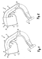
- einen Schnitt durch ein Ansaugsystem für eine Brennkraftmaschine mit einem zweiteiligen Saugrohr und einem Luftsammler, wobei ein austauschbares Saugrohrteil mit einer Deckelschale des Luftsammlers ein gemeinsames Bauteil bildet und ein an diesem Saugrohrteil ausgebildeter Rohrendstutzen in den Innenraum des Luftsammlers einragt,
- Fig. 2
- eine Fig. 1 entsprechende Darstellung, jedoch mit einem kürzer ausgeführten, in den Luftsammler einragenden Rohrendstutzen am austauschbaren Saugrohrteil.
- Fig. 1
- 1 shows a section through an intake system for an internal combustion engine with a two-part intake manifold and an air collector, an exchangeable intake manifold part with a cover shell of the air collector forming a common component and a pipe end connector formed on this intake pipe part protruding into the interior of the air collector,
- Fig. 2
- a representation corresponding to FIG. 1, but with a shorter tube end fitting protruding into the air collector on the interchangeable suction tube part.
In den Figuren sind gleiche Bauteile mit gleichen Bezugszeichen versehen.The same components with the same reference symbols are used in the figures Mistake.
Das in Fig. 1 dargestellte Ansaugsystem 1 für eine Brennkraftmaschine
umfasst einen Luftsammler 2 sowie mehrere, vom Luftsammler
2 abzweigende Saugrohre 3, von denen in Fig. 1 jedoch
nur eines im Schnitt dargestellt ist, wobei die Saugrohre zu
den Zylindereinlässen der Brennkraftmaschine geführt und über
einen Flansch 10 am Zylinderkopf der Brennkraftmaschine zu befestigen
sind. Sowohl der Luftsammler 2 als auch jedes Saugrohr
3 sind zweiteilig ausgebildet. Jedes Saugrohr 3 ist längsgeteilt
und besteht aus zwei Saugrohrteilen 4 und 5, von denen
das obere Saugrohrteil 4 eine austauschbare Oberschale und das
untere Saugrohrteil 5 eine fest stehende Unterschale bildet.
Der Luftsammler 2 besteht aus einem Kasten 6 und einer austauschbaren
Deckelschale 7. Die Deckelschale 7 bildet mit dem
oberen, austauschbaren bzw. einsetzbaren Saugrohrteil 4 ein gemeinsames,
einteiliges Bauteil. Der Kasten 6 des Luftsammlers 2
bildet mit dem unteren Saugrohrteil 5 - der Unterschale des
Saugrohres 3 - ebenfalls ein einteiliges Bauteil. Luftsammler
und Saugrohr sind zweckmäßig als Kunststoff-Spritzgussbauteil
hergestellt, wobei die Deckelschale 7 des Luftsammlers 2 mit
dem oberen Saugrohrteil 4 ein gemeinsames Spritzgussteil und in
entsprechender Weise der Kasten 6 des Luftsammlers mit dem unteren
Saugrohrteil 5 ein gemeinsames Spritzgussteil bildet.The intake system 1 shown in FIG. 1 for an internal combustion engine
comprises an air collector 2 and several, from the air collector
2 branching suction pipes 3, of which, however, in Fig. 1
only one is shown in section, with the suction pipes too
led and over the cylinder inlets of the internal combustion engine
to attach a
Die Deckelschale 7 sowie das mit der Deckelschale zusammenhängende
obere Saugrohrteil 4 sind lösbar und austauschbar ausgeführt
und können über Befestigungseinrichtungen 11 bzw. 12 mit
dem Kasten 6 bzw. dem unteren Saugrohrteil 5 verbunden werden.
Oberes und unteres Saugrohrteil können auch unlösbar miteinander
verbunden werden, beispielsweise durch Verschweißen.The lid shell 7 and that related to the lid shell
upper
Einteilig mit dem oberen, austauschbaren Saugrohrteil 4 ist ein
Rohrendstutzen 8 ausgebildet, welcher in Zusammenbauposition in
den Innenraum des Luftsammlers 2 einragt und sich zu seiner offenen
Seite hin trompetenartig erweitert. Dieser Rohrendstutzen
8 ist als in Umfangsrichtung durchgehend umlaufendes Rohr ausgeführt,
wohingegen der außerhalb des Luftsammlers liegende Abschnitt
des oberen Saugrohrteiles 4 als Halbschale ausgeführt
ist, die in Zusammenbaulage vom unteren Saugrohrteil 5 komplementär
zu einem gemeinsamen Saugrohr ergänzt wird.One piece with the upper, interchangeable
Wie dem Vergleich zwischen den Fig. 1 und 2 zu entnehmen, kann durch eine Variation der Länge des Rohrendstutzens 8 die Gesamtlänge des Saugrohres 3 variiert werden, wobei die sonstige Geometrie des Ansaugsystems unverändert beibehalten werden kann. Gegebenenfalls kann es aber auch zweckmäßig sein, alternativ oder zusätzlich die Geometrie der Deckelschale 7 des Luftsammlers 2 zu variieren, um ebenfalls eine Änderung der Saugrohrlänge und/oder des Luftvolumens in dem Luftsammler und dem Saugrohr zu erreichen; auch dieser Fall ist in den Figuren dargestellt, in denen sich die Deckelschalengeometrie unterscheidet. As can be seen from the comparison between FIGS. 1 and 2 the total length by varying the length of the pipe end connector 8 of the suction pipe 3 can be varied, the other The geometry of the intake system can be retained unchanged can. If necessary, it can also be useful, alternatively or additionally the geometry of the lid shell 7 of the Air collector 2 to vary, also to change the Suction pipe length and / or the air volume in the air collector and to reach the intake manifold; this case is also in the figures shown, in which the lid shell geometry differs.
Am Rohrendstutzen 8 ist ein einteiliger, radial über die Außenwand
des Rohrendstutzens überstehender Anschlag 9 ausgebildet,
welcher in Einbaulage an der Innenwand des Kastens des Luftsammlers
2 anliegt. Der Anschlag 9 stellt eine Montageerleichterung
dar.At the pipe end piece 8 is a one-piece, radially over the
Claims (8)
dadurch gekennzeichnet, dass der Luftsammler (2) mit einem der Saugrohrteile (5) ein zusammenhängendes, einteiliges Basisteil bildet und das zweite Saugrohrteil (4) als einsetzbares Wechselteil ausgeführt ist, das eine Wandschale des Luftsammlers (2) bildet.Intake system (1) for an internal combustion engine, with an air collector (2) into which combustion air is to be introduced, and a suction pipe (3) which branches off from the air collector (2) and consists of at least two longitudinally divided suction pipe parts (4, 5),
characterized in that the air collector (2) forms a cohesive, one-piece base part with one of the intake manifold parts (5) and the second intake manifold part (4) is designed as a replaceable part which forms a wall shell of the air collector (2).
dadurch gekennzeichnet, dass die Wandschale die Deckelschale (7) des Luftsammlers (2) bildet.Intake system according to claim 1,
characterized in that the wall shell forms the cover shell (7) of the air collector (2).
dadurch gekennzeichnet, dass ein Rohrendstutzen (8) des einsetzbares Saugrohrteils (4) in den Innenraum des Luftsammlers (2) einragt.Intake system according to claim 1 or 2,
characterized in that a pipe end piece (8) of the insertable suction pipe part (4) protrudes into the interior of the air collector (2).
dadurch gekennzeichnet, dass am Rohrendstutzen (8) ein radial überstehender Anschlag (9) angeordnet ist.Intake system according to claim 3,
characterized in that a radially projecting stop (9) is arranged on the pipe end connector (8).
dadurch gekennzeichnet, dass der Rohrendstutzen (8) an der Innenwand des Luftsammlers (2) abgestützt ist.Intake system according to claim 4,
characterized in that the pipe end connector (8) is supported on the inner wall of the air collector (2).
dadurch gekennzeichnet, dass verschiedene einsetzbare Saugrohrteile (4) sich in der Länge des einragenden Rohrendstutzens (8) unterscheiden.Intake system according to one of claims 3 to 5,
characterized in that different usable suction tube parts (4) differ in the length of the protruding tube end piece (8).
dadurch gekennzeichnet, dass der Luftsammler (2) und die Saugrohrteile (4, 5) aus Kunststoff bestehen.Intake system according to one of claims 1 to 6,
characterized in that the air collector (2) and the suction pipe parts (4, 5) consist of plastic.
dadurch gekennzeichnet, dass verschiedene einsetzbare Saugrohrteile (4) sich in der Gestalt des mit ihnen verbundenen Wandteiles des Luftsammlers (2) unterscheiden.Intake system according to one of claims 1 to 7,
characterized in that different usable suction pipe parts (4) differ in the shape of the wall part of the air collector (2) connected to them.
Applications Claiming Priority (2)
| Application Number | Priority Date | Filing Date | Title |
|---|---|---|---|
| DE10252784A DE10252784A1 (en) | 2002-11-13 | 2002-11-13 | Intake system for an internal combustion engine |
| DE10252784 | 2002-11-13 |
Publications (3)
| Publication Number | Publication Date |
|---|---|
| EP1420160A2 true EP1420160A2 (en) | 2004-05-19 |
| EP1420160A3 EP1420160A3 (en) | 2006-02-15 |
| EP1420160B1 EP1420160B1 (en) | 2011-07-20 |
Family
ID=32115476
Family Applications (1)
| Application Number | Title | Priority Date | Filing Date |
|---|---|---|---|
| EP03103352A Expired - Lifetime EP1420160B1 (en) | 2002-11-13 | 2003-09-11 | Air intake arrangement for an internal combustion engine |
Country Status (5)
| Country | Link |
|---|---|
| US (1) | US6889648B2 (en) |
| EP (1) | EP1420160B1 (en) |
| JP (1) | JP4381106B2 (en) |
| AT (1) | ATE517247T1 (en) |
| DE (1) | DE10252784A1 (en) |
Families Citing this family (4)
| Publication number | Priority date | Publication date | Assignee | Title |
|---|---|---|---|---|
| JP4636907B2 (en) * | 2005-03-11 | 2011-02-23 | 株式会社Roki | Intake manifold |
| US7552796B2 (en) * | 2006-04-27 | 2009-06-30 | United Technologies Corporation | Turbine engine tailcone resonator |
| EP1988264A1 (en) * | 2007-05-02 | 2008-11-05 | Mann+Hummel Gmbh | Air intake manifold including a plenum reducer insert |
| JP5541622B2 (en) | 2009-11-02 | 2014-07-09 | ヤマハ発動機株式会社 | Ship propulsion machine and ship |
Citations (5)
| Publication number | Priority date | Publication date | Assignee | Title |
|---|---|---|---|---|
| US4175504A (en) * | 1975-01-15 | 1979-11-27 | Bayerische Motoren Werke Ag | Air induction system for an internal combustion engine |
| FR2494343A1 (en) * | 1980-11-17 | 1982-05-21 | Metallurg Ste Aveyronnaise | Complex cast IC engine inlet manifold - made of separate pressure cast parts adhesively bonded together with lugs crimped over tabs on opposite part |
| US5813380A (en) * | 1993-12-10 | 1998-09-29 | Mitsubishi Jidosha Kogyo Kabushiki Kaisha | Suction control device for multiple cylinder internal combustion engine |
| US20020144668A1 (en) * | 1999-09-18 | 2002-10-10 | Thomas Schermuly | Intake device for an internal combustion engine |
| US20020195076A1 (en) * | 2001-06-20 | 2002-12-26 | Toyota Jidosha Kabushiki Kaisha | Variable intake device for internal combustion engines and method for manufacturing the device |
Family Cites Families (2)
| Publication number | Priority date | Publication date | Assignee | Title |
|---|---|---|---|---|
| US4664075A (en) * | 1985-10-30 | 1987-05-12 | General Motors Corporation | Symmetric manifold |
| US5651338A (en) * | 1996-03-26 | 1997-07-29 | Pacheco; Allan A. | Adjustable induction manifold system |
-
2002
- 2002-11-13 DE DE10252784A patent/DE10252784A1/en not_active Withdrawn
-
2003
- 2003-09-11 AT AT03103352T patent/ATE517247T1/en active
- 2003-09-11 EP EP03103352A patent/EP1420160B1/en not_active Expired - Lifetime
- 2003-11-10 JP JP2003380315A patent/JP4381106B2/en not_active Expired - Fee Related
- 2003-11-13 US US10/706,293 patent/US6889648B2/en not_active Expired - Fee Related
Patent Citations (5)
| Publication number | Priority date | Publication date | Assignee | Title |
|---|---|---|---|---|
| US4175504A (en) * | 1975-01-15 | 1979-11-27 | Bayerische Motoren Werke Ag | Air induction system for an internal combustion engine |
| FR2494343A1 (en) * | 1980-11-17 | 1982-05-21 | Metallurg Ste Aveyronnaise | Complex cast IC engine inlet manifold - made of separate pressure cast parts adhesively bonded together with lugs crimped over tabs on opposite part |
| US5813380A (en) * | 1993-12-10 | 1998-09-29 | Mitsubishi Jidosha Kogyo Kabushiki Kaisha | Suction control device for multiple cylinder internal combustion engine |
| US20020144668A1 (en) * | 1999-09-18 | 2002-10-10 | Thomas Schermuly | Intake device for an internal combustion engine |
| US20020195076A1 (en) * | 2001-06-20 | 2002-12-26 | Toyota Jidosha Kabushiki Kaisha | Variable intake device for internal combustion engines and method for manufacturing the device |
Also Published As
| Publication number | Publication date |
|---|---|
| US6889648B2 (en) | 2005-05-10 |
| DE10252784A1 (en) | 2004-06-09 |
| JP2004162710A (en) | 2004-06-10 |
| EP1420160B1 (en) | 2011-07-20 |
| JP4381106B2 (en) | 2009-12-09 |
| ATE517247T1 (en) | 2011-08-15 |
| US20040149248A1 (en) | 2004-08-05 |
| EP1420160A3 (en) | 2006-02-15 |
Similar Documents
| Publication | Publication Date | Title |
|---|---|---|
| EP2723470B1 (en) | Plate filter element | |
| EP2501922B1 (en) | Intake pipe section and intake module | |
| DE19626251A1 (en) | Air duct system | |
| DE102012000806A1 (en) | Resonator system for noise reduction of air filter system of gas inlet system of engine of motor vehicle, has housing and insertion part, where housing is designed such that its inner portion is designed as hollow space | |
| DE102017210921A1 (en) | Vehicle air duct for reducing intake noise | |
| DE202013103960U1 (en) | resonator | |
| EP1403506B1 (en) | Silencer for the reduction of air noise and method for the production thereof | |
| DE102005030457A1 (en) | coupling system | |
| DE102011015238A1 (en) | Multipart air guide channel for use in engine compartment of vehicle operated by internal combustion engine, has body-side channel section and engine-side channel section, where both channel sections are connected axially to each other | |
| DE102012221555A1 (en) | Filter top shell, filter and method for producing a filter top shell | |
| DE10335261A1 (en) | Compressor and / or turbine wheel for a secondary air conveyor | |
| EP1420160B1 (en) | Air intake arrangement for an internal combustion engine | |
| EP1422413B1 (en) | Air intake system | |
| DE102015224440A1 (en) | Cylinder head cover | |
| WO1997015755A1 (en) | Intake pipe | |
| EP1520977B1 (en) | Intake device for a pre-cleaning device in connection with a fan cover | |
| EP1288485B1 (en) | Intake pipe with mounting flange and insert to reinforce the flange | |
| DE19846281A1 (en) | Air feed system, particularly suction system for internal combustion engine, has collection chamber with clean air inlet and at least one connected suction tube together with by-pass conduit for excess compressed clean air | |
| EP2592289A2 (en) | Shaft passage of a housing of an internal combustion engine and bearing ring of a shaft passage | |
| DE102004024465A1 (en) | intake system | |
| DE102008047468A1 (en) | Filter device for internal combustion engines | |
| DE102010022117B4 (en) | Noise protection device for noise reduction of internal combustion engines | |
| DE10156213A1 (en) | throttle body | |
| DE102011009634A1 (en) | Turbocharger for motor vehicle, has outlet flange, inlet flange and clevis mounting flange which are connected with each other | |
| DE20320861U1 (en) | Vehicle internal combustion engine air filtering device, has casing with partitions defining respective conduits for conducting air inside casing and air pipes connecting with air inlet and air outlet at one side of casing |
Legal Events
| Date | Code | Title | Description |
|---|---|---|---|
| PUAI | Public reference made under article 153(3) epc to a published international application that has entered the european phase |
Free format text: ORIGINAL CODE: 0009012 |
|
| AK | Designated contracting states |
Kind code of ref document: A2 Designated state(s): AT BE BG CH CY CZ DE DK EE ES FI FR GB GR HU IE IT LI LU MC NL PT RO SE SI SK TR |
|
| AX | Request for extension of the european patent |
Extension state: AL LT LV MK |
|
| PUAL | Search report despatched |
Free format text: ORIGINAL CODE: 0009013 |
|
| AK | Designated contracting states |
Kind code of ref document: A3 Designated state(s): AT BE BG CH CY CZ DE DK EE ES FI FR GB GR HU IE IT LI LU MC NL PT RO SE SI SK TR |
|
| AX | Request for extension of the european patent |
Extension state: AL LT LV MK |
|
| 17P | Request for examination filed |
Effective date: 20060224 |
|
| 17Q | First examination report despatched |
Effective date: 20060807 |
|
| AKX | Designation fees paid |
Designated state(s): AT BE BG CH CY CZ DE DK EE ES FI FR GB GR HU IE IT LI LU MC NL PT RO SE SI SK TR |
|
| GRAP | Despatch of communication of intention to grant a patent |
Free format text: ORIGINAL CODE: EPIDOSNIGR1 |
|
| GRAS | Grant fee paid |
Free format text: ORIGINAL CODE: EPIDOSNIGR3 |
|
| GRAA | (expected) grant |
Free format text: ORIGINAL CODE: 0009210 |
|
| AK | Designated contracting states |
Kind code of ref document: B1 Designated state(s): AT BE BG CH CY CZ DE DK EE ES FI FR GB GR HU IE IT LI LU MC NL PT RO SE SI SK TR |
|
| REG | Reference to a national code |
Ref country code: GB Ref legal event code: FG4D Free format text: NOT ENGLISH |
|
| REG | Reference to a national code |
Ref country code: CH Ref legal event code: EP |
|
| REG | Reference to a national code |
Ref country code: DE Ref legal event code: R096 Ref document number: 50313828 Country of ref document: DE Effective date: 20110908 |
|
| REG | Reference to a national code |
Ref country code: NL Ref legal event code: VDEP Effective date: 20110720 |
|
| PG25 | Lapsed in a contracting state [announced via postgrant information from national office to epo] |
Ref country code: SE Free format text: LAPSE BECAUSE OF FAILURE TO SUBMIT A TRANSLATION OF THE DESCRIPTION OR TO PAY THE FEE WITHIN THE PRESCRIBED TIME-LIMIT Effective date: 20110720 Ref country code: FI Free format text: LAPSE BECAUSE OF FAILURE TO SUBMIT A TRANSLATION OF THE DESCRIPTION OR TO PAY THE FEE WITHIN THE PRESCRIBED TIME-LIMIT Effective date: 20110720 Ref country code: PT Free format text: LAPSE BECAUSE OF FAILURE TO SUBMIT A TRANSLATION OF THE DESCRIPTION OR TO PAY THE FEE WITHIN THE PRESCRIBED TIME-LIMIT Effective date: 20111121 Ref country code: NL Free format text: LAPSE BECAUSE OF FAILURE TO SUBMIT A TRANSLATION OF THE DESCRIPTION OR TO PAY THE FEE WITHIN THE PRESCRIBED TIME-LIMIT Effective date: 20110720 |
|
| REG | Reference to a national code |
Ref country code: IE Ref legal event code: FD4D |
|
| PG25 | Lapsed in a contracting state [announced via postgrant information from national office to epo] |
Ref country code: SI Free format text: LAPSE BECAUSE OF FAILURE TO SUBMIT A TRANSLATION OF THE DESCRIPTION OR TO PAY THE FEE WITHIN THE PRESCRIBED TIME-LIMIT Effective date: 20110720 Ref country code: GR Free format text: LAPSE BECAUSE OF FAILURE TO SUBMIT A TRANSLATION OF THE DESCRIPTION OR TO PAY THE FEE WITHIN THE PRESCRIBED TIME-LIMIT Effective date: 20111021 Ref country code: CY Free format text: LAPSE BECAUSE OF FAILURE TO SUBMIT A TRANSLATION OF THE DESCRIPTION OR TO PAY THE FEE WITHIN THE PRESCRIBED TIME-LIMIT Effective date: 20110720 |
|
| BERE | Be: lapsed |
Owner name: MANN+HUMMEL G.M.B.H. Effective date: 20110930 |
|
| PG25 | Lapsed in a contracting state [announced via postgrant information from national office to epo] |
Ref country code: IE Free format text: LAPSE BECAUSE OF FAILURE TO SUBMIT A TRANSLATION OF THE DESCRIPTION OR TO PAY THE FEE WITHIN THE PRESCRIBED TIME-LIMIT Effective date: 20110720 Ref country code: SK Free format text: LAPSE BECAUSE OF FAILURE TO SUBMIT A TRANSLATION OF THE DESCRIPTION OR TO PAY THE FEE WITHIN THE PRESCRIBED TIME-LIMIT Effective date: 20110720 Ref country code: CZ Free format text: LAPSE BECAUSE OF FAILURE TO SUBMIT A TRANSLATION OF THE DESCRIPTION OR TO PAY THE FEE WITHIN THE PRESCRIBED TIME-LIMIT Effective date: 20110720 Ref country code: MC Free format text: LAPSE BECAUSE OF NON-PAYMENT OF DUE FEES Effective date: 20110930 |
|
| REG | Reference to a national code |
Ref country code: CH Ref legal event code: PL |
|
| PLBE | No opposition filed within time limit |
Free format text: ORIGINAL CODE: 0009261 |
|
| STAA | Information on the status of an ep patent application or granted ep patent |
Free format text: STATUS: NO OPPOSITION FILED WITHIN TIME LIMIT |
|
| PG25 | Lapsed in a contracting state [announced via postgrant information from national office to epo] |
Ref country code: EE Free format text: LAPSE BECAUSE OF FAILURE TO SUBMIT A TRANSLATION OF THE DESCRIPTION OR TO PAY THE FEE WITHIN THE PRESCRIBED TIME-LIMIT Effective date: 20110720 Ref country code: RO Free format text: LAPSE BECAUSE OF FAILURE TO SUBMIT A TRANSLATION OF THE DESCRIPTION OR TO PAY THE FEE WITHIN THE PRESCRIBED TIME-LIMIT Effective date: 20110720 Ref country code: IT Free format text: LAPSE BECAUSE OF FAILURE TO SUBMIT A TRANSLATION OF THE DESCRIPTION OR TO PAY THE FEE WITHIN THE PRESCRIBED TIME-LIMIT Effective date: 20110720 |
|
| REG | Reference to a national code |
Ref country code: FR Ref legal event code: ST Effective date: 20120531 |
|
| 26N | No opposition filed |
Effective date: 20120423 |
|
| GBPC | Gb: european patent ceased through non-payment of renewal fee |
Effective date: 20111020 |
|
| PG25 | Lapsed in a contracting state [announced via postgrant information from national office to epo] |
Ref country code: DK Free format text: LAPSE BECAUSE OF FAILURE TO SUBMIT A TRANSLATION OF THE DESCRIPTION OR TO PAY THE FEE WITHIN THE PRESCRIBED TIME-LIMIT Effective date: 20110720 Ref country code: BE Free format text: LAPSE BECAUSE OF NON-PAYMENT OF DUE FEES Effective date: 20110930 |
|
| PG25 | Lapsed in a contracting state [announced via postgrant information from national office to epo] |
Ref country code: CH Free format text: LAPSE BECAUSE OF NON-PAYMENT OF DUE FEES Effective date: 20110930 Ref country code: LI Free format text: LAPSE BECAUSE OF NON-PAYMENT OF DUE FEES Effective date: 20110930 |
|
| REG | Reference to a national code |
Ref country code: DE Ref legal event code: R097 Ref document number: 50313828 Country of ref document: DE Effective date: 20120423 |
|
| PG25 | Lapsed in a contracting state [announced via postgrant information from national office to epo] |
Ref country code: FR Free format text: LAPSE BECAUSE OF NON-PAYMENT OF DUE FEES Effective date: 20110930 Ref country code: GB Free format text: LAPSE BECAUSE OF NON-PAYMENT OF DUE FEES Effective date: 20111020 |
|
| REG | Reference to a national code |
Ref country code: AT Ref legal event code: MM01 Ref document number: 517247 Country of ref document: AT Kind code of ref document: T Effective date: 20110911 |
|
| PG25 | Lapsed in a contracting state [announced via postgrant information from national office to epo] |
Ref country code: AT Free format text: LAPSE BECAUSE OF NON-PAYMENT OF DUE FEES Effective date: 20110911 |
|
| PG25 | Lapsed in a contracting state [announced via postgrant information from national office to epo] |
Ref country code: ES Free format text: LAPSE BECAUSE OF FAILURE TO SUBMIT A TRANSLATION OF THE DESCRIPTION OR TO PAY THE FEE WITHIN THE PRESCRIBED TIME-LIMIT Effective date: 20111031 |
|
| PG25 | Lapsed in a contracting state [announced via postgrant information from national office to epo] |
Ref country code: LU Free format text: LAPSE BECAUSE OF NON-PAYMENT OF DUE FEES Effective date: 20110911 |
|
| PG25 | Lapsed in a contracting state [announced via postgrant information from national office to epo] |
Ref country code: BG Free format text: LAPSE BECAUSE OF FAILURE TO SUBMIT A TRANSLATION OF THE DESCRIPTION OR TO PAY THE FEE WITHIN THE PRESCRIBED TIME-LIMIT Effective date: 20111020 |
|
| PG25 | Lapsed in a contracting state [announced via postgrant information from national office to epo] |
Ref country code: TR Free format text: LAPSE BECAUSE OF FAILURE TO SUBMIT A TRANSLATION OF THE DESCRIPTION OR TO PAY THE FEE WITHIN THE PRESCRIBED TIME-LIMIT Effective date: 20110720 |
|
| PG25 | Lapsed in a contracting state [announced via postgrant information from national office to epo] |
Ref country code: HU Free format text: LAPSE BECAUSE OF FAILURE TO SUBMIT A TRANSLATION OF THE DESCRIPTION OR TO PAY THE FEE WITHIN THE PRESCRIBED TIME-LIMIT Effective date: 20110720 |
|
| PGFP | Annual fee paid to national office [announced via postgrant information from national office to epo] |
Ref country code: DE Payment date: 20150922 Year of fee payment: 13 |
|
| REG | Reference to a national code |
Ref country code: DE Ref legal event code: R119 Ref document number: 50313828 Country of ref document: DE |
|
| PG25 | Lapsed in a contracting state [announced via postgrant information from national office to epo] |
Ref country code: DE Free format text: LAPSE BECAUSE OF NON-PAYMENT OF DUE FEES Effective date: 20170401 |