EP1520977B1 - Intake device for a pre-cleaning device in connection with a fan cover - Google Patents
Intake device for a pre-cleaning device in connection with a fan cover Download PDFInfo
- Publication number
- EP1520977B1 EP1520977B1 EP04104763.0A EP04104763A EP1520977B1 EP 1520977 B1 EP1520977 B1 EP 1520977B1 EP 04104763 A EP04104763 A EP 04104763A EP 1520977 B1 EP1520977 B1 EP 1520977B1
- Authority
- EP
- European Patent Office
- Prior art keywords
- fan cover
- section
- fan
- duct
- cleaning device
- Prior art date
- Legal status (The legal status is an assumption and is not a legal conclusion. Google has not performed a legal analysis and makes no representation as to the accuracy of the status listed.)
- Expired - Lifetime
Links
Images

Classifications
-
- F—MECHANICAL ENGINEERING; LIGHTING; HEATING; WEAPONS; BLASTING
- F02—COMBUSTION ENGINES; HOT-GAS OR COMBUSTION-PRODUCT ENGINE PLANTS
- F02M—SUPPLYING COMBUSTION ENGINES IN GENERAL WITH COMBUSTIBLE MIXTURES OR CONSTITUENTS THEREOF
- F02M35/00—Combustion-air cleaners, air intakes, intake silencers, or induction systems specially adapted for, or arranged on, internal-combustion engines
- F02M35/10—Air intakes; Induction systems
- F02M35/10006—Air intakes; Induction systems characterised by the position of elements of the air intake system in direction of the air intake flow, i.e. between ambient air inlet and supply to the combustion chamber
- F02M35/10013—Means upstream of the air filter; Connection to the ambient air
-
- F—MECHANICAL ENGINEERING; LIGHTING; HEATING; WEAPONS; BLASTING
- F02—COMBUSTION ENGINES; HOT-GAS OR COMBUSTION-PRODUCT ENGINE PLANTS
- F02M—SUPPLYING COMBUSTION ENGINES IN GENERAL WITH COMBUSTIBLE MIXTURES OR CONSTITUENTS THEREOF
- F02M35/00—Combustion-air cleaners, air intakes, intake silencers, or induction systems specially adapted for, or arranged on, internal-combustion engines
- F02M35/02—Air cleaners
- F02M35/04—Air cleaners specially arranged with respect to engine, to intake system or specially adapted to vehicle; Mounting thereon ; Combinations with other devices
- F02M35/06—Air cleaners specially arranged with respect to engine, to intake system or specially adapted to vehicle; Mounting thereon ; Combinations with other devices combined or associated with engine's cooling blower or fan, or with flywheel
-
- F—MECHANICAL ENGINEERING; LIGHTING; HEATING; WEAPONS; BLASTING
- F02—COMBUSTION ENGINES; HOT-GAS OR COMBUSTION-PRODUCT ENGINE PLANTS
- F02M—SUPPLYING COMBUSTION ENGINES IN GENERAL WITH COMBUSTIBLE MIXTURES OR CONSTITUENTS THEREOF
- F02M35/00—Combustion-air cleaners, air intakes, intake silencers, or induction systems specially adapted for, or arranged on, internal-combustion engines
- F02M35/10—Air intakes; Induction systems
- F02M35/10209—Fluid connections to the air intake system; their arrangement of pipes, valves or the like
- F02M35/10229—Fluid connections to the air intake system; their arrangement of pipes, valves or the like the intake system acting as a vacuum or overpressure source for auxiliary devices, e.g. brake systems; Vacuum chambers
-
- F—MECHANICAL ENGINEERING; LIGHTING; HEATING; WEAPONS; BLASTING
- F02—COMBUSTION ENGINES; HOT-GAS OR COMBUSTION-PRODUCT ENGINE PLANTS
- F02M—SUPPLYING COMBUSTION ENGINES IN GENERAL WITH COMBUSTIBLE MIXTURES OR CONSTITUENTS THEREOF
- F02M35/00—Combustion-air cleaners, air intakes, intake silencers, or induction systems specially adapted for, or arranged on, internal-combustion engines
- F02M35/16—Combustion-air cleaners, air intakes, intake silencers, or induction systems specially adapted for, or arranged on, internal-combustion engines characterised by use in vehicles
- F02M35/161—Arrangement of the air intake system in the engine compartment, e.g. with respect to the bonnet or the vehicle front face
-
- F—MECHANICAL ENGINEERING; LIGHTING; HEATING; WEAPONS; BLASTING
- F02—COMBUSTION ENGINES; HOT-GAS OR COMBUSTION-PRODUCT ENGINE PLANTS
- F02M—SUPPLYING COMBUSTION ENGINES IN GENERAL WITH COMBUSTIBLE MIXTURES OR CONSTITUENTS THEREOF
- F02M35/00—Combustion-air cleaners, air intakes, intake silencers, or induction systems specially adapted for, or arranged on, internal-combustion engines
- F02M35/16—Combustion-air cleaners, air intakes, intake silencers, or induction systems specially adapted for, or arranged on, internal-combustion engines characterised by use in vehicles
- F02M35/164—Heavy duty vehicles, e.g. trucks, trains, agricultural or construction machines
-
- F—MECHANICAL ENGINEERING; LIGHTING; HEATING; WEAPONS; BLASTING
- F02—COMBUSTION ENGINES; HOT-GAS OR COMBUSTION-PRODUCT ENGINE PLANTS
- F02M—SUPPLYING COMBUSTION ENGINES IN GENERAL WITH COMBUSTIBLE MIXTURES OR CONSTITUENTS THEREOF
- F02M35/00—Combustion-air cleaners, air intakes, intake silencers, or induction systems specially adapted for, or arranged on, internal-combustion engines
- F02M35/02—Air cleaners
Definitions
- the present invention relates to a suction device for a pre-cleaning device in conjunction with a fan cowling, as they are often used for internal combustion engines in vehicles.
- the present invention relates to a device which is used for a pre-cleaning device for pre-cleaning the combustion air of an internal combustion engine.
- the present invention relates to a suction device, which provides a vacuum or a vacuum to such a pre-cleaning device.
- Air intake systems for internal combustion engines of agricultural or industrial utility vehicles usually have pre-purification devices with which dirt particles are removed from the intake air before the intake air reaches the air filter.
- Many pre-cleaning facilities require a negative pressure or a vacuum in order to extract dirt particles from the fresh air entering the air intake system or to clean the fresh air from dirt particles.
- Exhaust systems were used to provide the required vacuum.
- such an exhaust system entails a restriction in the exhaust gas of the internal combustion engine, increases the noise emission and the cost of an exhaust muffler and / or an exhaust pipe.
- a check valve is required to prevent backflow of high temperature gases into the pre-cleaner.
- hose connectors that are suitable for high temperatures must be used.
- a fan cowl suction device is usually formed by an opening in the fan cowl, which is connected by means of a hose connection with the pre-cleaning device.
- a disadvantage of such a suction device is that this additional hose connections and hose clamps are needed.
- Modern agricultural tractors or other utility vehicles may require an elongated fan shroud to fill the space between a radiator and a fan.
- An example of such a system is in US 5427502 shown.
- the object underlying the invention is seen to provide and further develop a suction device of the type mentioned, by which the above-mentioned problems are overcome.
- a suction device should be specified and further developed, which can be produced more cheaply and which preferably has fewer individual parts.
- Such a suction device should be particularly compatible with known or existing manufacturing and manufacturing techniques.
- the suction device according to the invention is suitable for a pre-cleaning device in conjunction with a fan cowl.
- the pre-cleaning device has a suction port.
- the fan cowl is located between a fan and a radiator.
- the Aspirator has a channel which is provided on a surface of the fan cowl.
- the channel communicates or connects between a - formed in particular in the form of a nozzle - portal and an aperture, which is arranged on the fan cowl in the vicinity of the fan.
- the pre-cleaning device can be attached to the fan cowling in such a way that the suction port is in direct communication with the port via the portal.
- the required negative pressure or the required vacuum for sucking for the pre-cleaning device is provided by a generated by the fan air flow or air flow through the channel.
- a fan cowl which has a suction device integrated therein.
- the fan cowling has an upper and a lower section.
- the upper portion is formed complementary to the lower portion, so that in the assembled state, a channel between the fan and the cooling module or the radiator of the vehicle is formed.
- the upper portion of the fan shroud has a channel formed by an air duct section in the fan shroud and a similar air duct section in a duct cover.
- the channel is formed when the channel cover is fitted to the upper portion of the fan cowl.
- a first end of the channel terminates at an aperture located at the end of the fan cowl near the fan.
- a second end of the channel is formed bent upward and forms a nozzle or a portal on the upper side of the Channel cover.
- a pre-cleaning device has an air inlet and an air outlet and is pressurized via a suction with negative pressure.
- the suction port is located at the portal or nozzle of the channel shroud.
- the suction port is directly connected to the portal or the nozzle of the channel cover, without intervening, for example, a hose connection is required.
- the suction port is thus in communication with the air passage and the aperture located in the fan shroud.
- the vacuum required to operate the aspirator is provided by the air movement generated by the fan, the movement of air between the air inlet of the prepurifier and the aperture located in the fan shroud being via the aspiration port and the air channel. Since the pre-cleaning device is directly adaptable or adaptable to the air duct, no additional vacuum hoses or hose clamps are required. Therefore, space under a hood can be saved in a particularly advantageous manner.
- the fan cover preferably has a first section and a second section.
- the first and second sections when assembled, could form a complete fan cowl.
- An assembly of the two sections together could be made possible in that the first and the second section each have at least one flange, wherein the flange of the first section is formed complementary to the flange of the second section.
- the first section of the fan cowling has an air channel formed therein.
- the channel or the air duct could be formed in two parts.
- the air channel has a first channel section formed in the first section and a second channel section formed in a channel cover.
- each channel portion may have a cross section such that a channel is formed between the channel cover and the first portion when the channel cover is attached to the first portion.
- the overall cross section of the channel could be circular or elliptical.
- the channel cover on each side of the channel portion could have flanges corresponding to complementary surfaces of the first portion of the fan shroud, such that the channel cover can be fastened to the first portion of the fan shroud.
- the channel has a passage with a substantially circular cross-section, and extends between the channel cover and the first portion of the fan cowl.
- the channel connects the suction port with the aperture formed on the fan shroud.
- the channel cover could include a nozzle which forms the portal to the channel when the channel cover is mounted to the first portion of the fan cowl.
- the first section of the fan cowling could have at least one fastening projection such that the suction port of the pre-cleaner is arranged to communicate with the gantry which could be formed by the nozzle of the duct cover when the pre-cleaner is mounted to the mounting bosses.
- the fan shroud could be molded from a thermoplastic or thermosetting material.
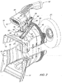
- the Fig. 1 to 3 show a fan cowl 10 having a suction device integrated therein.
- the Fan cover 10 comprises an upper portion 12 and a lower portion 14 and is preferably formed of thermoplastic or duoplastic material with a corresponding manufacturing method, in particular a compression molding process.
- the upper portion 12 and the lower portion 14 are configured to matingly mate with each other on mating flanges 16 to form a channel (or passage or passage) between a fan and a fan To form a cooling module or a radiator of a vehicle.
- a first end 18 of the fan shroud 10 is formed to be disposed in the vicinity of a radiator not shown in the figures, whereas a second end 20 of the fan shroud 10 is formed to be disposed in the vicinity of the fan 22.
- air is drawn from the fan 22 through the radiator.
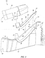
- the Fig. 2 and 3 it can be seen that the upper portion 12 of the fan cowl 10 has an air channel 24.
- the air channel 24 has a molded in the upper portion 12 of the fan cover 10 molded channel portion 26.
- the air channel 24 further includes a channel portion 28 formed in a channel cover 30.
- the channel cover 30 may be mounted in a complementary manner to the top portion 12 of the fan cowling 10.
- the channel sections 26 and 28 each have a substantially semicircular cross-section, so that the air passage 24 or the air passage in the mounted state of the channel cover 30 at the upper portion 12 of the fan cowl 10 has a substantially circular cross-section.
- a first end 32 of the channel portion 26 terminates at an aperture 34 which is disposed at the second end 20 of the fan cowl 10.
- the aperture 34 is disposed in the vicinity of the fan 22.
- a second end 36 of the channel portion 26 is formed bent upward and terminates substantially in the middle or in the front third between the first end 18 and the second end 20 of the fan cowl 10.
- the channel cover 30 comprises two flanges 38, which on both sides of Channel portion 28 are arranged to fasten the channel cover 30 to the surfaces 40 complementary to the flanges 38, which are formed on both sides of the channel portion 26 to attach.
- Fastening tabs 42 are provided in both the flanges 38 of the channel cover 30 and in the surfaces 40 to secure the channel cover 30 to the fan cowl 10 with appropriate fasteners.
- a first end 44 of the channel portion 28 terminates at one end of the channel cover 30, whereby in the assembled state of the channel cover 30, the circular aperture 34 is completed by the fan cowling 10.
- a mouthpiece or nozzle 46 is provided at the top of the channel cover 30. The nozzle 46 communicates with the second end 48 of the channel portion 28 in a region in which the channel portion 26 of the upper portion 12 of the fan shroud 10 is formed bent upward. Accordingly, the air channel 24 has a channel with a substantially circular cross-section extending from the aperture 34 near the fan 22 and the top-mounted nozzle 46 of the channel cover 30 when the channel cover 30 is secured in place.
- a pre-cleaner 50 for the intake air for the internal combustion engine comprises an air intake 52, a suction port 54 and an air exhaust 56.
- air is drawn through the intake manifold 52 and dirt particles are removed from the intake air and the intake air is cleaned and the purified air exits through the connected to an air inlet, not shown, of an internal combustion engine, also not shown, air outlet 56 from the pre-cleaning device 50.
- the suction for the pre-cleaning device 50 is provided by the vacuum generated by the fan 22 via the suction port 54, which will be described below.
- Two fastening projections 58 are provided on the upper portion 12 of the fan cowl 10.
- the fastening projections 58 correspond to fastening tabs 60, which are arranged on the housing of the pre-cleaning device 50.
- the pre-cleaning device 50 can be attached to the fan cowling 10 by means of appropriate fastening means.
- the negative pressure required for the pre-cleaning device 50 is caused by an air movement caused by the fan 22, wherein the air movement between the intake port 52 of the pre-cleaning device 50 and the aperture 34 of the fan cowl 10 via the suction port 54 and the Air duct 24 extends. Since the pre-cleaning device 50 is mounted or adapted directly to the air duct 24 of the fan cowl 10, no additional, suitable for negative pressure suction hoses or hose clamps are required, which advantageously less space under the hood of the vehicle is needed.
Landscapes
- Engineering & Computer Science (AREA)
- Chemical & Material Sciences (AREA)
- Combustion & Propulsion (AREA)
- Mechanical Engineering (AREA)
- General Engineering & Computer Science (AREA)
- Structures Of Non-Positive Displacement Pumps (AREA)
- Cleaning In General (AREA)
- Cleaning Of Streets, Tracks, Or Beaches (AREA)
- Nozzles For Electric Vacuum Cleaners (AREA)
- Jet Pumps And Other Pumps (AREA)
Description
Die vorliegende Erfindung betrifft eine Ansaugvorrichtung für eine Vorreinigungseinrichtung in Verbindung mit einer Ventilatorverkleidung, wie sie häufig für Verbrennungsmotoren bei Fahrzeugen eingesetzt werden. Insbesondere betrifft die vorliegende Erfindung eine Vorrichtung, welche für eine Vorreinigungseinrichtung zum Vorreinigen der Verbrennungsluft eines Verbrennungsmotors zum Einsatz kommt. Im Konkreten betrifft die vorliegende Erfindung eine Ansaugvorrichtung, welche einer solchen Vorreinigungseinrichtung einen Unterdruck bzw. ein Vakuum zur Verfügung stellt.The present invention relates to a suction device for a pre-cleaning device in conjunction with a fan cowling, as they are often used for internal combustion engines in vehicles. In particular, the present invention relates to a device which is used for a pre-cleaning device for pre-cleaning the combustion air of an internal combustion engine. Specifically, the present invention relates to a suction device, which provides a vacuum or a vacuum to such a pre-cleaning device.
Lufteinlasssysteme für Verbrennungsmotoren von landwirtschaftlichen oder industriellen Nutzfahrzeugen weisen üblicherweise Vorreinigungseinrichtungen auf, mit welchen Schmutzpartikel von der Ansaugluft entfernt werden, bevor die Ansaugluft zu dem Luftfilter gelangt. Viele Vorreinigungseinrichtungen benötigen einen Unterdruck bzw. ein Vakuum, um Schmutzpartikel aus der in das Lufteinlasssystem eintretenden Frischluft herauszuziehen bzw. die Frischluft von Schmutzpartikeln zu reinigen. Auspuffsauganlagen wurden verwendet, um das erforderliche Vakuum zur Verfügung zu stellen. Eine solche Auspuffsauganlage bringt jedoch eine Beschränkung in dem Abgas des Verbrennungsmotors mit sich, erhöht die Geräuschemission und die Kosten eines Auspuff-Schalldämpfers und/oder eines Auspuffrohrs. Weiterhin ist ein Sperrventil erforderlich, um einen Rückfluss von Gasen hoher Temperatur in die Vorreinigungseinrichtung zu verhindern. Schließlich müssen Schlauchverbinder verwendet werden, die für hohe Temperaturen geeignet sind.Air intake systems for internal combustion engines of agricultural or industrial utility vehicles usually have pre-purification devices with which dirt particles are removed from the intake air before the intake air reaches the air filter. Many pre-cleaning facilities require a negative pressure or a vacuum in order to extract dirt particles from the fresh air entering the air intake system or to clean the fresh air from dirt particles. Exhaust systems were used to provide the required vacuum. However, such an exhaust system entails a restriction in the exhaust gas of the internal combustion engine, increases the noise emission and the cost of an exhaust muffler and / or an exhaust pipe. Furthermore, a check valve is required to prevent backflow of high temperature gases into the pre-cleaner. Finally, hose connectors that are suitable for high temperatures must be used.
Eine andere Möglichkeit stellt die Verwendung einer Ansaugvorrichtung für eine Ventilatorverkleidung als eine Quelle für den Unterdruck für eine Vorreinigungseinrichtung dar. Eine solche Ansaugvorrichtung ist üblicherweise durch eine Öffnung in der Ventilatorverkleidung gebildet, welche mit Hilfe einer Schlauchverbindung mit der Vorreinigungseinrichtung verbunden ist. Ein Nachteil einer solchen Ansaugvorrichtung ist der, dass hierfür zusätzliche Schlauchverbindungen und Schlauchklemmen benötigt werden. Moderne landwirtschaftliche Traktoren oder andere Nutzfahrzeuge benötigen unter Umständen eine länglich ausgebildete Ventilatorverkleidung, um den Freiraum zwischen einem Kühler und einem Lüfter auszufüllen. Ein Beispiel eines solches systems ist in der
Die der Erfindung zugrunde liegende Aufgabe wird darin gesehen, eine Ansaugvorrichtung der eingangs genannten Art anzugeben und weiterzubilden, durch die die vorgenannten Probleme überwunden werden. Insbesondere soll eine Ansaugvorrichtung angegeben und weitergebildet werden, die kostengünstiger produziert werden kann und welche vorzugsweise weniger Einzelteile aufweist. Eine solche Ansaugvorrichtung sollte insbesondere kompatibel zu bekannten bzw. bestehenden Herstellungs- und Fertigungstechniken sein.The object underlying the invention is seen to provide and further develop a suction device of the type mentioned, by which the above-mentioned problems are overcome. In particular, a suction device should be specified and further developed, which can be produced more cheaply and which preferably has fewer individual parts. Such a suction device should be particularly compatible with known or existing manufacturing and manufacturing techniques.
Die Aufgabe wird erfindungsgemäß durch die Lehre des Patentanspruchs 1 gelöst. Weitere vorteilhafte Ausgestaltungen und Weiterbildungen der Erfindung gehen aus den Unteransprüchen hervor.The object is achieved by the teaching of claim 1. Further advantageous embodiments and modifications of the invention will become apparent from the dependent claims.
Die erfindungsgemäße Ansaugvorrichtung ist für eine Vorreinigungseinrichtung in Verbindung mit einer Ventilatorverkleidung geeignet. Die Vorreinigungseinrichtung weist einen Ansauganschluss auf. Die Ventilatorverkleidung ist zwischen einem Lüfter und einem Kühler angeordnet. Die Ansaugvorrichtung weist einen Kanal auf, welcher an einer Oberfläche der Ventilatorverkleidung vorgesehen ist. Der Kanal kommuniziert bzw. verbindet zwischen einem - insbesondere in Form einer Düse ausgebildeten - Portal und einer Apertur, die an der Ventilatorverkleidung in der Nähe des Lüfters angeordnet ist. Die Vorreinigungseinrichtung ist an der Ventilatorverkleidung derart anbringbar, dass der Ansauganschluss über das Portal mit dem Kanal in unmittelbarer Verbindung steht. Der erforderliche Unterdruck bzw. das erforderliche Vakuum zum Ansaugen für die Vorreinigungseinrichtung wird von einem von dem Lüfter erzeugten Luftfluss bzw. Luftstrom durch den Kanal zur Verfügung gestellt.The suction device according to the invention is suitable for a pre-cleaning device in conjunction with a fan cowl. The pre-cleaning device has a suction port. The fan cowl is located between a fan and a radiator. The Aspirator has a channel which is provided on a surface of the fan cowl. The channel communicates or connects between a - formed in particular in the form of a nozzle - portal and an aperture, which is arranged on the fan cowl in the vicinity of the fan. The pre-cleaning device can be attached to the fan cowling in such a way that the suction port is in direct communication with the port via the portal. The required negative pressure or the required vacuum for sucking for the pre-cleaning device is provided by a generated by the fan air flow or air flow through the channel.
Gemäß einer besonders bevorzugten Ausführungsform ist eine Ventilatorverkleidung vorgesehen, welche eine darin integrierte Ansaugvorrichtung aufweist. Die Ventilatorverkleidung weist einen oberen und einen unteren Abschnitt auf. Der obere Abschnitt ist komplementär zu dem unteren Abschnitt ausgebildet, so dass hierdurch im zusammengefügten Zustand ein Kanal zwischen dem Lüfter und dem Kühlmodul bzw. den Kühler des Fahrzeugs gebildet ist. Der obere Abschnitt der Ventilatorverkleidung weist einen Kanal auf, welcher von einem Luftkanalabschnitt in der Ventilatorverkleidung und einem hierzu ähnlichen Luftkanalabschnitt in einer Kanalabdeckung gebildet ist. Somit wird der Kanal gebildet, wenn die Kanalabdeckung an dem oberen Abschnitt der Ventilatorverkleidung montiert bzw. angepasst ist. Ein erstes Ende des Kanals endet an einer Apertur, welche am Ende der Ventilatorverkleidung in der Nähe des Lüfters angeordnet ist. Ein zweites Ende des Kanals ist nach oben gebogen ausgebildet und bildet eine Düse bzw. ein Portal an der oberen Seite der Kanalabdeckung. Eine Vorreinigungseinrichtung weist einen Lufteinlass und einen Luftauslass auf und wird über einen Ansauganschluss mit Unterdruck beaufschlagt. Wenn die Vorreinigungseinrichtung an der Ventilatorverkleidung montiert ist, ist der Ansauganschluss an bzw. in dem Portal oder der Düse der Kanalabdeckung angeordnet. Mit anderen Worten ist der Ansauganschluss unmittelbar mit dem Portal oder der Düse der Kanalabdeckung verbunden, ohne dass dazwischen z.B. eine Schlauchverbindung erforderlich ist. Der Ansauganschluss ist somit mit dem Luftkanal und der in der Ventilatorverkleidung angeordneten Apertur in Kommunikation bzw. Verbindung. Das zum Betrieb der Ansaugvorrichtung erforderliche Vakuum wird durch die von dem Lüfter erzeugte Luftbewegung bereitgestellt, wobei die Luftbewegung zwischen dem Lufteinlass der Vorreinigungseinrichtung und der in der Ventilatorverkleidung angeordneten Apertur über den Ansauganschluss und den Luftkanal erfolgt. Da die Vorreinigungseinrichtung unmittelbar an den Luftkanal anpassbar bzw. adaptierbar ist, sind keine zusätzlichen Unterdruckschläuche oder Schlauchklemmen erforderlich. Daher kann in ganz besonders vorteilhafter Weise Bauraum unter einer Motorhaube gespart werden.According to a particularly preferred embodiment, a fan cowl is provided, which has a suction device integrated therein. The fan cowling has an upper and a lower section. The upper portion is formed complementary to the lower portion, so that in the assembled state, a channel between the fan and the cooling module or the radiator of the vehicle is formed. The upper portion of the fan shroud has a channel formed by an air duct section in the fan shroud and a similar air duct section in a duct cover. Thus, the channel is formed when the channel cover is fitted to the upper portion of the fan cowl. A first end of the channel terminates at an aperture located at the end of the fan cowl near the fan. A second end of the channel is formed bent upward and forms a nozzle or a portal on the upper side of the Channel cover. A pre-cleaning device has an air inlet and an air outlet and is pressurized via a suction with negative pressure. When the pre-cleaner is mounted to the fan shroud, the suction port is located at the portal or nozzle of the channel shroud. In other words, the suction port is directly connected to the portal or the nozzle of the channel cover, without intervening, for example, a hose connection is required. The suction port is thus in communication with the air passage and the aperture located in the fan shroud. The vacuum required to operate the aspirator is provided by the air movement generated by the fan, the movement of air between the air inlet of the prepurifier and the aperture located in the fan shroud being via the aspiration port and the air channel. Since the pre-cleaning device is directly adaptable or adaptable to the air duct, no additional vacuum hoses or hose clamps are required. Therefore, space under a hood can be saved in a particularly advantageous manner.
Bevorzugt weist die Ventilatorverkleidung einen ersten Abschnitt und einen zweiten Abschnitt auf. Der erste und der zweite Abschnitt könnte im zusammengesetzten Zustand eine vollständige Ventilatorverkleidung bilden. Eine Montage der beiden Abschnitte aneinander könnte dadurch ermöglicht werden, dass der erste und der zweite Abschnitt jeweils mindestens einen Flansch aufweist, wobei der Flansch des ersten Abschnitts komplementär zum Flansch des zweiten Abschnitts ausgebildet ist.The fan cover preferably has a first section and a second section. The first and second sections, when assembled, could form a complete fan cowl. An assembly of the two sections together could be made possible in that the first and the second section each have at least one flange, wherein the flange of the first section is formed complementary to the flange of the second section.
Bevorzugt weist der erste Abschnitt der Ventilatorverkleidung einen darin ausgebildeten Luftkanal auf. Auch der Kanal bzw. der Luftkanal könnte zweiteilig ausgebildet sein. So wäre es denkbar, dass der Luftkanal einen in dem ersten Abschnitt ausgebildeten ersten Kanalabschnitt und einen in einer Kanalabdeckung ausgebildeten zweiten Kanalabschnitt aufweist.Preferably, the first section of the fan cowling has an air channel formed therein. Also, the channel or the air duct could be formed in two parts. Thus, it would be conceivable that the air channel has a first channel section formed in the first section and a second channel section formed in a channel cover.
Nun könnte jeder Kanalabschnitt einen Querschnitt derart aufweisen, dass ein Kanal zwischen der Kanalabdeckung und dem ersten Abschnitt ausgebildet ist, wenn die Kanalabdeckung an dem ersten Abschnitt angebracht ist. Der Gesamtquerschnitt des Kanals könnte kreisförmig oder ellipsenförmig sein. Im Konkreten könnte die Kanalabdeckung an jeder Seite des Kanalabschnitts Flansche aufweisen, welche zu dazu komplementär ausgebildeten Oberflächen des ersten Abschnitts der Ventilatorverkleidung korrespondieren, so dass die Kanalabdeckung passend oder dichtend an dem ersten Abschnitt der Ventilatorverkleidung befestigbar ist.Now, each channel portion may have a cross section such that a channel is formed between the channel cover and the first portion when the channel cover is attached to the first portion. The overall cross section of the channel could be circular or elliptical. Concretely, the channel cover on each side of the channel portion could have flanges corresponding to complementary surfaces of the first portion of the fan shroud, such that the channel cover can be fastened to the first portion of the fan shroud.
Besonders bevorzugt weist der Kanal eine Passage mit einem im Wesentlichen kreisförmigen Querschnitt auf, und erstreckt sich zwischen der Kanalabdeckung und dem ersten Abschnitt der Ventilatorverkleidung. Der Kanal verbindet den Ansauganschluss mit der an der Ventilatorverkleidung ausgebildeten Apertur.More preferably, the channel has a passage with a substantially circular cross-section, and extends between the channel cover and the first portion of the fan cowl. The channel connects the suction port with the aperture formed on the fan shroud.
Die Kanalabdeckung könnte eine Düse aufweisen, welche das Portal zu dem Kanal bildet, wenn die Kanalabdeckung an dem ersten Abschnitt der Ventilatorverkleidung montiert ist.The channel cover could include a nozzle which forms the portal to the channel when the channel cover is mounted to the first portion of the fan cowl.
Zur Befestigung der Vorreinigungseinrichtung an der Ventilatorverkleidung könnte der erste Abschnitt der Ventilatorverkleidung mindestens einen Befestigungsvorsprung aufweisen, so dass der Ansauganschluss der Vorreinigungseinrichtung kommunizierend zu dem Portal angeordnet ist, welches durch die Düse der Kanalabdeckung gebildet sein könnte, wenn die Vorreinigungseinrichtung an den Befestigungsvorsprüngen montiert ist.To attach the pre-cleaning device on the fan cowling, the first section of the fan cowling could have at least one fastening projection such that the suction port of the pre-cleaner is arranged to communicate with the gantry which could be formed by the nozzle of the duct cover when the pre-cleaner is mounted to the mounting bosses.
Die Ventilatorverkleidung könnte aus einem thermoplastischen oder duroplastischen Material geformt sein.The fan shroud could be molded from a thermoplastic or thermosetting material.
Anhand der Zeichnung, die ein Ausführungsbeispiel der Erfindung zeigt, werden nachfolgend die Erfindung sowie weitere Vorteile und vorteilhafte Weiterbildungen und Ausgestaltungen der Erfindung näher beschrieben und erläutert.Reference to the drawing, which shows an embodiment of the invention, the invention and further advantages and advantageous developments and refinements of the invention are described and explained in more detail below.
Es zeigt:
- Fig. 1
- in einer perspektivischen Ansicht eine schematische Darstellung eines ersten erfindungsgemäßen Ausführungsbeispiels einer Ansaugvorrichtung für eine Vorreinigungseinrichtung in Verbindung mit einer Ventilatorverkleidung,
- Fig. 2
- in einer Explosionsansicht eine schematische Darstellung des Ausführungsbeispiels aus
Fig. 1 und - Fig. 3
- eine Schnittdarstellung des Ausführungsbeispiels aus
Fig. 2 entlang der Linie 3-3.
- Fig. 1
- 3 is a perspective view of a first embodiment according to the invention of a suction device for a pre-cleaning device in conjunction with a fan cowl,
- Fig. 2
- in an exploded view of a schematic representation of the embodiment of
Fig. 1 and - Fig. 3
- a sectional view of the embodiment of
Fig. 2 along the line 3-3.
Die
Dementsprechend ist ein erstes Ende 18 der Ventilatorverkleidung 10 ausgebildet, um in der Nähe eines in den Fig. nicht gezeigten Kühlers angeordnet zu werden, wohingegen ein zweites Ende 20 der Ventilatorverkleidung 10 ausgebildet ist, um in der Nähe des Lüfters 22 angeordnet zu werden. Somit wird Luft von dem Lüfter 22 durch den Kühler gezogen. Den
Ein erstes Ende 32 des Kanalabschnitts 26 endet an einer Apertur 34, die an dem zweiten Ende 20 der Ventilatorverkleidung 10 angeordnet ist. Die Apertur 34 ist in der Nähe des Lüfters 22 angeordnet. Ein zweites Ende 36 des Kanalabschnitts 26 ist nach oben gebogen ausgebildet und endet im Wesentlichen in der Mitte beziehungsweise im vorderen Drittel zwischen dem ersten Ende 18 und dem zweiten Ende 20 der Ventilatorverkleidung 10. Die Kanalabdeckung 30 umfasst zwei Flansche 38, welche an beiden Seiten des Kanalabschnitts 28 angeordnet sind, um die Kanalabdeckung 30 an den zu den Flanschen 38 komplementär ausgebildeten Oberflächen 40, welche an beiden Seiten des Kanalabschnitts 26 ausgebildet sind, zu befestigen. Befestigungsapersturen 42 sind sowohl in den Flanschen 38 der Kanalabdeckung 30 als auch in den Oberflächen 40 vorgesehen, um die Kanalabdeckung 30 an der Ventilatorverkleidung 10 mit entsprechenden Befestigungsmitteln zu befestigen.A
Ein erstes Ende 44 des Kanalabschnitts 28 endet an einem Ende der Kanalabdeckung 30, wodurch im montierten Zustand der Kanalabdeckung 30 die kreisförmige Apertur 34 durch die Ventilatorverkleidung 10 vervollständigt wird. Ein Mundstück oder eine Düse 46 ist an der Oberseite der Kanalabdeckung 30 vorgesehen. Die Düse 46 kommuniziert mit dem zweiten Ende 48 des Kanalabschnitts 28 in einem Bereich, in welchem der Kanalabschnitt 26 des oberen Abschnitts 12 der Ventilatorverkleidung 10 nach oben gebogen ausgebildet ist. Dementsprechend weist der Luftkanal 24 einen Kanal mit einem im Wesentlichen kreisförmigen Querschnitt auf, der sich von der Apertur 34 nahe des Lüfters 22 und der oben angeordneten Düse 46 der Kanalabdeckung 30 erstreckt, wenn die Kanalabdeckung 30 an ihrem vorgesehenen Ort befestigt ist.A
Eine Vorreinigungseinrichtung 50 für die Ansaugluft für den Verbrennungsmotor umfasst einen Lufteinlass bzw. einen Ansaugstutzen 52, einen Ansauganschluss 54 und einen Luftabzug bzw. einen Luftauslass 56. Im Betrieb wird Luft durch den Ansaugstutzen 52 angezogen und Schmutzpartikel werden von der Ansaugluft entfernt bzw. die Ansaugluft wird gereinigt und die gereinigte Luft tritt durch den mit einem nicht gezeigten Lufteinlass eines ebenfalls nicht gezeigten Verbrennungsmotors verbundenen Luftauslass 56 aus der Vorreinigungseinrichtung 50 aus. Die Saugwirkung für die Vorreinigungsvorrichtung 50 wird von dem vom Lüfter 22 erzeugten Vakuum bzw. Unterdruck über den Ansauganschluss 54 bereitgestellt, was im Folgenden beschrieben wird.A pre-cleaner 50 for the intake air for the internal combustion engine comprises an
Es sind zwei Befestigungsvorsprünge 58 an dem oberen Abschnitt 12 der Ventilatorverkleidung 10 vorgesehen. Die Befestigungsvorsprünge 58 korrespondieren zu Befestigungslaschen 60, welche am Gehäuse der Vorreinigungseinrichtung 50 angeordnet sind. Hiermit kann die Vorreinigungseinrichtung 50 an der Ventilatorverkleidung 10 mit Hilfe entsprechender Befestigungsmittel befestigt werden. Wenn die Befestigungslaschen 60 zu den Befestigungsvorsprünge 58 ausgerichtet sind, ist der Ansauganschluss 54 derart positioniert, dass er gleitend in die Düse 46 der Kanalabdeckung 30 eingeführt werden kann. Dementsprechend steht der Ansauganschluss 54 kommunizierend mit dem Luftkanal 24 und der Apertur 34 in Verbindung. Der für die Vorreinigungseinrichtung 50 erforderliche Unterdruck wird durch eine von dem Lüfter 22 verursachte Luftbewegung bewirkt, wobei die Luftbewegung sich zwischen dem Ansaugstutzen 52 der Vorreinigungseinrichtung 50 und der Apertur 34 der Ventilatorverkleidung 10 über den Ansauganschluss 54 und den Luftkanal 24 erstreckt. Da die Vorreinigungseinrichtung 50 unmittelbar an dem Luftkanal 24 der Ventilatorverkleidung 10 angebracht bzw. angepasst ist, sind keine zusätzlichen, für Unterdruck geeignete Ansaugschläuche oder Schlauchschellen erforderlich, wodurch in vorteilhafter Weise weniger Bauraum unter der Motorhaube des Fahrzeugs benötigt wird.Two
Auch wenn die Erfindung lediglich anhand eines Ausführungsbeispiels beschrieben wurde, erschließen sich für den Fachmann im Lichte der vorstehenden Beschreibung sowie der Zeichnung viele verschiedenartige Alternativen, Modifikationen und Varianten, die unter die vorliegende Erfindung fallen.Although the invention has been described by way of example only, in light of the foregoing description and the drawings, those skilled in the art will recognize many different alternatives, modifications and variations which are within the scope of the present invention.
Claims (9)
- Fan cover with an intake device for a pre-cleaning device with an intake connection (54), wherein the fan cover (10) is arranged between a cooling fan (22) and a radiator, wherein the intake device has an air duct (24) provided on a surface of the fan cover, wherein the air duct (24) runs between a nozzle (46) and an aperture (34) which is arranged on the fan cover (10) in the vicinity of the cooling fan (22), wherein the pre-cleaning device (50) can be attached to the fan cover (10) in such a manner that the intake connection (54) is directly connected via the nozzle (46) to the air duct (24), and wherein the negative pressure required for operating the pre-cleaning device (50) is caused by an air flow which is produced in the air duct (24) by means of the cooling fan (22), characterized in that the air duct (24) is formed by a compression-duct section (26) formed in a first section (12) of the fan cover (10) and by a duct section (28) formed in a duct covering (30).
- Fan cover according to Claim 1, wherein the fan cover (10) furthermore has a second section (14), wherein preferably the first and the second section (12, 14) in the assembled state form a complete fan cover.
- Fan cover according to Claim 2, wherein the first and the second section (12, 14) each have at least one flange (16), wherein the flange (16) of the first section (12) is formed in a complementary manner to the flange (16) of the second section (14).
- Fan cover according to one of the preceding claims, wherein each duct section (26, 28) has a cross section in such a manner that the air duct (24) between the duct covering (30) and the first section (12) is formed when the duct covering (30) is attached to the first section (12).
- Fan cover according to one of the preceding claims, characterized in that the duct covering (30) on each side of the duct section (28) has flanges (38) which correspond to surface (40), which are formed in a complementary manner with respect thereto, of the first section (12) of the fan cover (10) such that the duct covering (30) can be fastened in a fitting or sealing manner to the first section (12) of the fan cover (10).
- Fan cover according to one of the preceding claims, wherein the air duct (24) is formed by a passage, which is of substantially circular design, between the duct covering (30) and the first section (12) of the fan cover (10), wherein said passage connects the intake connection (54) to the aperture (34) formed on the fan cover (10).
- Fan cover according to one of the preceding claims, wherein the nozzle (46) is provided on the duct covering (30), wherein said nozzle forms a portal to the air duct (24) when the duct covering (30) is mounted on the first section (12) of the fan cover (10).
- Fan cover according to one of the preceding claims, wherein the first section (12) of the fan cover (10) has at least one fastening projection (58) for fastening the pre-cleaning device (50) to the fan cover (10) such that the intake connection (54) of the pre-cleaning device (50) is arranged in communication with the nozzle (46) when the pre-cleaning device (50) is mounted on the fastening projections (58).
- Fan cover according to one of the preceding claims, wherein the fan cover (10) is formed from a thermoplastic or thermosetting material.
Applications Claiming Priority (2)
| Application Number | Priority Date | Filing Date | Title |
|---|---|---|---|
| US10/675,619 US6976825B2 (en) | 2003-09-30 | 2003-09-30 | Integrated aspirator and fan shroud |
| US675619 | 2003-09-30 |
Publications (3)
| Publication Number | Publication Date |
|---|---|
| EP1520977A2 EP1520977A2 (en) | 2005-04-06 |
| EP1520977A3 EP1520977A3 (en) | 2011-08-17 |
| EP1520977B1 true EP1520977B1 (en) | 2016-06-29 |
Family
ID=34314004
Family Applications (1)
| Application Number | Title | Priority Date | Filing Date |
|---|---|---|---|
| EP04104763.0A Expired - Lifetime EP1520977B1 (en) | 2003-09-30 | 2004-09-29 | Intake device for a pre-cleaning device in connection with a fan cover |
Country Status (3)
| Country | Link |
|---|---|
| US (1) | US6976825B2 (en) |
| EP (1) | EP1520977B1 (en) |
| BR (2) | BRPI0403667A (en) |
Families Citing this family (9)
| Publication number | Priority date | Publication date | Assignee | Title |
|---|---|---|---|---|
| US20060081353A1 (en) * | 2004-10-19 | 2006-04-20 | Inniger Steven W | Split access fan shroud |
| US7278504B2 (en) * | 2004-10-25 | 2007-10-09 | Deere & Company | Integrated fan shroud air intake system |
| US20100071978A1 (en) * | 2008-09-22 | 2010-03-25 | Clark Equipment Company | Combustion air cleaner scavenge system |
| US8256551B2 (en) * | 2009-12-30 | 2012-09-04 | Agco Corporation | Agricultural vehicle cooling assembly fan shroud with seals for pass-through cooling and exhaust tubes |
| US9222448B2 (en) * | 2014-02-14 | 2015-12-29 | Cnh Industrial America Llc | Air intake system for a work vehicle with improved fan aspiration |
| DE102019117148B4 (en) * | 2019-06-26 | 2022-09-29 | CASO Holding GmbH | Suction housing and device comprising a suction housing for sucking off fumes and a method for sucking off fumes by means of the device and use of the device for sucking off fumes |
| USD1009936S1 (en) * | 2019-08-26 | 2024-01-02 | Velossa Tech Engineering Inc. | Ram-air intake |
| DE102019213195A1 (en) | 2019-09-02 | 2021-03-04 | Deere & Company | Fan cowl for a vehicle system |
| US11719203B2 (en) * | 2020-02-05 | 2023-08-08 | Cnh Industrial America Llc | System and method for cleaning an air intake screen of a work vehicle |
Family Cites Families (6)
| Publication number | Priority date | Publication date | Assignee | Title |
|---|---|---|---|---|
| US2197503A (en) * | 1938-04-30 | 1940-04-16 | Oliver Farm Equipment Co | Air intake for air cleaners |
| JPS58187575A (en) * | 1982-04-26 | 1983-11-01 | Mazda Motor Corp | Fresh-air introducing mechanism for air cleaner |
| DE3232583A1 (en) * | 1982-09-02 | 1984-03-08 | Daimler-Benz Ag, 7000 Stuttgart | Device for cleaning the intake air of an internal combustion engine |
| US5427502A (en) * | 1994-03-28 | 1995-06-27 | Deere & Company | Fan shroud aspirator |
| US5564513A (en) * | 1994-07-12 | 1996-10-15 | Automotive Performance International, Inc. | Air filter housing for automobile internal combustion engine |
| US6588524B2 (en) * | 2001-05-31 | 2003-07-08 | Deere & Company | Vacuum pump aspirator for work vehicle pre-cleaner |
-
2003
- 2003-09-30 US US10/675,619 patent/US6976825B2/en not_active Expired - Fee Related
-
2004
- 2004-08-31 BR BR0403667-0A patent/BRPI0403667A/en active IP Right Grant
- 2004-08-31 BR BRMU8403639-7U patent/BRMU8403639Y1/en not_active IP Right Cessation
- 2004-09-29 EP EP04104763.0A patent/EP1520977B1/en not_active Expired - Lifetime
Also Published As
| Publication number | Publication date |
|---|---|
| EP1520977A2 (en) | 2005-04-06 |
| BRMU8403639Y1 (en) | 2014-07-22 |
| US6976825B2 (en) | 2005-12-20 |
| EP1520977A3 (en) | 2011-08-17 |
| US20050069412A1 (en) | 2005-03-31 |
| BRPI0403667A (en) | 2005-06-07 |
Similar Documents
| Publication | Publication Date | Title |
|---|---|---|
| EP1290332B1 (en) | Air-filtration system | |
| DE10348575B4 (en) | Exhaust gas recirculation system for an internal combustion engine | |
| EP2501922B1 (en) | Intake pipe section and intake module | |
| DE19952136A1 (en) | Intake system | |
| DE20013534U1 (en) | Device for recirculating gas on an internal combustion engine | |
| WO1995006807A1 (en) | Throttle device | |
| EP0675268A1 (en) | Fan arrangement with aspirator | |
| DE19626251A1 (en) | Air duct system | |
| DE102011110285A1 (en) | Intake pipe element and compressor assembly thereof | |
| EP3095995A1 (en) | Charge air cooler | |
| EP1520977B1 (en) | Intake device for a pre-cleaning device in connection with a fan cover | |
| EP0840846A1 (en) | Unit and snap-action device therefor | |
| DE60009111T2 (en) | UNIT OF SUCTION PIPE AND CYLINDER HEAD COVER | |
| DE102004026105A1 (en) | Intake device for internal combustion engine of motor vehicle, has connection room and air outflow route which are arranged at connection direction of air inlet path with respect to dirty side room | |
| EP0254816B1 (en) | Crankcase ventilation in motor vehicles | |
| EP3236038B1 (en) | Hedge trimmer | |
| EP1422413B1 (en) | Air intake system | |
| EP0989295A2 (en) | Intake system for a combustion engine | |
| DE102017204785A1 (en) | Venturi module for a compressor housing | |
| EP1283351B1 (en) | Intake system for an internal combustion engine | |
| EP0832352B1 (en) | Pipe module | |
| DE102017223700A1 (en) | Ventilation system for a motor vehicle light | |
| EP3786458B1 (en) | Fan casing for a vehicle system | |
| DE102014117698B4 (en) | Insert type expansion pipe integrated air filter device and internal combustion engine intake system therefor | |
| DE102013224878A1 (en) | Intake system for use in secondary filter for internal combustion engine of vehicle, has air filter arrangement stands in fluid connection with intake manifold, and another air filter arrangement spaced apart from former filter arrangement |
Legal Events
| Date | Code | Title | Description |
|---|---|---|---|
| PUAI | Public reference made under article 153(3) epc to a published international application that has entered the european phase |
Free format text: ORIGINAL CODE: 0009012 |
|
| AK | Designated contracting states |
Kind code of ref document: A2 Designated state(s): AT BE BG CH CY CZ DE DK EE ES FI FR GB GR HU IE IT LI LU MC NL PL PT RO SE SI SK TR |
|
| AX | Request for extension of the european patent |
Extension state: AL HR LT LV MK |
|
| PUAL | Search report despatched |
Free format text: ORIGINAL CODE: 0009013 |
|
| AK | Designated contracting states |
Kind code of ref document: A3 Designated state(s): AT BE BG CH CY CZ DE DK EE ES FI FR GB GR HU IE IT LI LU MC NL PL PT RO SE SI SK TR |
|
| AX | Request for extension of the european patent |
Extension state: AL HR LT LV MK |
|
| RIC1 | Information provided on ipc code assigned before grant |
Ipc: F02M 35/10 20060101AFI20110714BHEP Ipc: F02M 35/02 20060101ALI20110714BHEP Ipc: F02M 35/16 20060101ALI20110714BHEP Ipc: F02M 35/06 20060101ALI20110714BHEP |
|
| 17P | Request for examination filed |
Effective date: 20120217 |
|
| AKX | Designation fees paid |
Designated state(s): DE FR GB IT |
|
| 17Q | First examination report despatched |
Effective date: 20120809 |
|
| GRAP | Despatch of communication of intention to grant a patent |
Free format text: ORIGINAL CODE: EPIDOSNIGR1 |
|
| INTG | Intention to grant announced |
Effective date: 20160120 |
|
| GRAS | Grant fee paid |
Free format text: ORIGINAL CODE: EPIDOSNIGR3 |
|
| GRAA | (expected) grant |
Free format text: ORIGINAL CODE: 0009210 |
|
| AK | Designated contracting states |
Kind code of ref document: B1 Designated state(s): DE FR GB IT |
|
| REG | Reference to a national code |
Ref country code: GB Ref legal event code: FG4D Free format text: NOT ENGLISH |
|
| REG | Reference to a national code |
Ref country code: DE Ref legal event code: R096 Ref document number: 502004015240 Country of ref document: DE |
|
| PGFP | Annual fee paid to national office [announced via postgrant information from national office to epo] |
Ref country code: DE Payment date: 20160819 Year of fee payment: 13 Ref country code: GB Payment date: 20160927 Year of fee payment: 13 |
|
| PG25 | Lapsed in a contracting state [announced via postgrant information from national office to epo] |
Ref country code: IT Free format text: LAPSE BECAUSE OF FAILURE TO SUBMIT A TRANSLATION OF THE DESCRIPTION OR TO PAY THE FEE WITHIN THE PRESCRIBED TIME-LIMIT Effective date: 20160629 |
|
| REG | Reference to a national code |
Ref country code: DE Ref legal event code: R097 Ref document number: 502004015240 Country of ref document: DE |
|
| PLBE | No opposition filed within time limit |
Free format text: ORIGINAL CODE: 0009261 |
|
| STAA | Information on the status of an ep patent application or granted ep patent |
Free format text: STATUS: NO OPPOSITION FILED WITHIN TIME LIMIT |
|
| 26N | No opposition filed |
Effective date: 20170330 |
|
| REG | Reference to a national code |
Ref country code: FR Ref legal event code: ST Effective date: 20170531 |
|
| PG25 | Lapsed in a contracting state [announced via postgrant information from national office to epo] |
Ref country code: FR Free format text: LAPSE BECAUSE OF NON-PAYMENT OF DUE FEES Effective date: 20160930 |
|
| REG | Reference to a national code |
Ref country code: DE Ref legal event code: R119 Ref document number: 502004015240 Country of ref document: DE |
|
| GBPC | Gb: european patent ceased through non-payment of renewal fee |
Effective date: 20170929 |
|
| PG25 | Lapsed in a contracting state [announced via postgrant information from national office to epo] |
Ref country code: GB Free format text: LAPSE BECAUSE OF NON-PAYMENT OF DUE FEES Effective date: 20170929 Ref country code: DE Free format text: LAPSE BECAUSE OF NON-PAYMENT OF DUE FEES Effective date: 20180404 |