EP1419948A1 - Tie rod apparatus and method for assembling a vacuum booster - Google Patents
Tie rod apparatus and method for assembling a vacuum booster Download PDFInfo
- Publication number
- EP1419948A1 EP1419948A1 EP03078208A EP03078208A EP1419948A1 EP 1419948 A1 EP1419948 A1 EP 1419948A1 EP 03078208 A EP03078208 A EP 03078208A EP 03078208 A EP03078208 A EP 03078208A EP 1419948 A1 EP1419948 A1 EP 1419948A1
- Authority
- EP
- European Patent Office
- Prior art keywords
- housing
- tie rod
- booster
- captive nut
- front wall
- Prior art date
- Legal status (The legal status is an assumption and is not a legal conclusion. Google has not performed a legal analysis and makes no representation as to the accuracy of the status listed.)
- Granted
Links
Images


Classifications
-
- B—PERFORMING OPERATIONS; TRANSPORTING
- B60—VEHICLES IN GENERAL
- B60T—VEHICLE BRAKE CONTROL SYSTEMS OR PARTS THEREOF; BRAKE CONTROL SYSTEMS OR PARTS THEREOF, IN GENERAL; ARRANGEMENT OF BRAKING ELEMENTS ON VEHICLES IN GENERAL; PORTABLE DEVICES FOR PREVENTING UNWANTED MOVEMENT OF VEHICLES; VEHICLE MODIFICATIONS TO FACILITATE COOLING OF BRAKES
- B60T13/00—Transmitting braking action from initiating means to ultimate brake actuator with power assistance or drive; Brake systems incorporating such transmitting means, e.g. air-pressure brake systems
- B60T13/10—Transmitting braking action from initiating means to ultimate brake actuator with power assistance or drive; Brake systems incorporating such transmitting means, e.g. air-pressure brake systems with fluid assistance, drive, or release
- B60T13/24—Transmitting braking action from initiating means to ultimate brake actuator with power assistance or drive; Brake systems incorporating such transmitting means, e.g. air-pressure brake systems with fluid assistance, drive, or release the fluid being gaseous
- B60T13/46—Vacuum systems
- B60T13/52—Vacuum systems indirect, i.e. vacuum booster units
- B60T13/567—Vacuum systems indirect, i.e. vacuum booster units characterised by constructional features of the casing or by its strengthening or mounting arrangements
- B60T13/5675—Supportstruts
Definitions
- This invention relates to vehicle brake systems, and more particularly to vacuum boosters for vehicle brake systems.
- Vehicles such as automobiles, trucks, buses, and motor homes typically include a dashboard at the front of the passenger compartment, having a power brake booster on the front of the dashboard connected by a push rod to a brake pedal mounted on the rear of the dashboard in the passenger compartment.
- a brake master cylinder, connected to the braking system, is mounted on the front end of the booster.
- one commonly used type of brake booster known as a vacuum booster, includes a housing apparatus 12 having a front housing 14 and a rear housing 16, joined together and defining a longitudinal axis 18 of the booster 10.
- the front housing 14 defines a front wall 20 of the housing 12 and an inner surface 22 of the front wall 20.
- the rear housing 16 defines a rear wall 24 of the housing 12 and an inner surface 26 of the rear wall 24.
- a tie rod 28 extends axially through holes 25, 27 in the front and rear walls 20, 24 respectively of the housing 12.
- the tie rod 28 has a first end 30 engaging the rear wall 24 of the housing 12, and a second end 32 engaging the front wall 20 of the housing 12.
- the first end 30 of the tie rod 28 includes an annular flange 36 welded or mechanically fastened to the inner surface 26 of the rear wall 24, and a threaded section 34 extending from the annular flange 36, through the hole 27 in the rear wall 24, for mounting the booster 10 on the front of a vehicle dashboard.
- the second end 32 of the tie rod 28 extends through the hole 25 in the front wall 20 of the housing 12, and is also threaded to receive a special sealing nut 38 that bears against the inner surface 22 of the front wall 20.
- the threaded portion of the second end 32 of the tie rod 28 extends outward beyond the front wall 20 of the booster 10, for mounting a brake master cylinder to be actuated by the booster 10.
- the position of the sealing nut 38 on the threads at the second end of the tie rod 28 is adjusted so that once the front and rear housings 14, 16 are joined together, the sealing nut 38 will be properly positioned for applying an axially directed force against the inner surface 22 of the front wall 20 of the housing 12 to achieve a desired axial distance between the front and rear walls 20, 24 of the housing 12.
- Setting the front and rear walls 20, 24 at a desired axial distance is required to allow proper pre-load of the front and rear housings 14, 16, and proper spacing between internal components of the booster 10, such as the booster piston 40 and a first and second diaphragm support 42, 44 that move with the piston 40, so that the booster 10 can function properly.
- the booster 10, of FIG. 1 is a tandem vacuum brake booster having a primary and a secondary diaphragm 46, 48, and a divider 41 that separate the interior of the housing 12 into primary and secondary vacuum chambers 50, 52, and primary and secondary high-pressure chambers 51, 53. These chambers must be sealed from one another for proper operation of the booster 10.
- Air tubes 54 adapted for sealing engagement with the primary diaphragm 46 and the divider 41 of the booster 10, provide sealed passageways for the tie rod 28 to pass through the primary vacuum and high pressure chambers 50, 51, without allowing leakage along the tie rod 28 between the primary vacuum and high pressure chambers 50, 51.
- Our invention provides a tie rod apparatus and method for adjusting the axial distance between the front and rear walls of the booster, from outside of the booster, after the booster has been assembled.
- a vacuum booster in one form of our invention, includes a housing having a front housing and a rear housing joined together and defining a longitudinal axis of the booster.
- the front housing defines a front wall of the housing and an inner surface of the front wall.
- the rear housing defines a rear wall of the housing and includes a captive nut having threads adapted for threaded engagement with a threaded end of a tie rod.
- the front and rear walls are spaced an axial distance from one another along the longitudinal axis.
- a tie rod extends axially through the housing and has a first end engaging the rear wall of the housing and a second end engaging the front wall of the housing. The first end of the tie rod has threads for engaging the threads of the captive nut in the rear wall of the housing.
- the second end of the tie rod has an axially facing surface thereof for applying an axially directed force against the inner surface front wall of the housing.
- the axial distance of the housing between the front and rear walls of the housing is adjusted by turning the tie rod, to thread the first end of the tie rod farther in or out of the captive nut.
- the booster in another form of our invention includes internal elements thereof axially separating the interior of the housing into fluid chambers sealed from one another, and the captive nut includes a tube extending axially therefrom along a part of the tie rod into the interior of the housing through one or more of the fluid chambers.
- the tube has a surface adapted for sealing engagement with the internal elements of the booster.
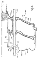
- FIG. 2 illustrates a first exemplary embodiment of a tandem brake booster 110, according to our invention.
- the booster 110 includes a housing 112 having a front housing 114 and a rear housing 116 joined together and defining a longitudinal axis 118 of the booster 110.
- the front housing 114 defines a front wall 120 of the housing 110 and an inner surface 122 of the front wall 120.
- the rear housing 116 defines a rear wall 124 of the housing 112, and includes one or more captive nuts 129 having threads adapted for threaded engagement with a threaded end of a tie rod 128.
- the captive nuts 129 are attached by a process such as welding, brazing, adhesive bonding, or other means of mechanically fastening, to an inside surface 126 of the rear wall 124 of the housing 112.
- the front and rear walls 114, 116 are spaced an axial distance from one another along the longitudinal axis 118.
- a tie rod 128 extends axially through the housing 112 and has a first end 130 engaging the rear wall 124 of the housing 112.
- a second end 132 of the tie rod 128 engages the front wall 114 of the housing 112.
- the first end 130 of the tie rod 128 has threads for engaging the threads of the captive nut 129 in the rear wall 124 of the housing 112.
- the second end 132 of the tie rod 128 has an annular flange 135 including an axially facing surface 137 thereof for applying an axially directed force against the inner surface 122 front wall 120 of the housing 112.
- the axial distance of the housing 112 between the front and rear walls 120, 124 of the housing 112 in a booster 110 according to our invention can be adjusted after the booster 110 is otherwise assembled, by turning the tie rod 128, to thread the first end 130 of the tie rod 128 farther in or out of the captive nut 126.
- one or both ends 130, 132 of the tie rod may be formed for engagement with a tool, such as a wrench.
- the threaded first end 130 of the tie rod 128 extends beyond the rear wall 124 of the booster, through the captive nut 129 and a hole 127 in the rear housing 116, for attaching the booster 110 to a mounting surface such as the front side of the dashboard of a vehicle.
- the second end 132 of the tie rod 28 includes a threaded portion 134 extending through a hole 125 in the front wall 120 and outward beyond the front wall 120 of the booster 110, for attaching a brake master cylinder to be actuated by the booster 110.
- a seal 136 in the form of an O-ring or another form of packing, disposed in a trepan groove in the annular flange 135 precludes leakage through the hole 125 around the tie rod 128.
- a sealant such as an anaerobic microencapsulated glue is applied to the threads of the first end 130 of the tie rod 128 engaging the tie rod 128 for precluding leakage the threads of the tie rod 128 and the captive nut 129.
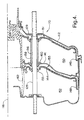
- FIG. 3 shows a second embodiment of a booster 110, according to our invention.
- the embodiment of FIG. 3 is identical to the embodiment shown in FIG. 2, except for the configuration of the second end 132 of the tie rod 128, and the manner in which the second end 132 of the tie rod 128 exerts an axial force against the inner surface 122 of the front wall 120 of the booster 110.
- the axially facing surface 137 of the tie rod 128 is provided in the form of a shoulder on the tie rod 128.
- the shoulder 137 bears against an annular sealing washer 138, clamped between the shoulder 137 and the inside surface 122 of the front wall 120.
- a seal 136 in the form of an O-ring or other type of packing is disposed in a trepan groove in the annular sealing washer 138 to preclude leakage through the hole 125 around the tie rod 128.
- FIG. 4 shows a third embodiment of a booster 110, according to our invention.
- the embodiment of FIG. 4 is identical to the embodiment shown in FIG. 3, except that the captive nut 129 includes a tube 156 extending into the booster 110 and having an outer surface 158 adapted for sealing engagement with internal components of the booster 110, in a manner precluding leakage along the tie rod 128 between internal fluid chambers within the booster 110.
- the booster 110 is a tandem vacuum brake booster 110 having a primary and a secondary diaphragm 146, 148, and a divider 141 that separate the interior of the housing 112 into primary and secondary vacuum chambers 150, 152, and primary and secondary high-pressure chambers 151, 153. These chambers must be sealed from one another for proper operation of the booster 110.
- the outer surface 158 of the tube 156 extending from the captive nut 129 is adapted for sealing engagement with the primary diaphragm 146, and with a seal 160 attached to the divider 141 of the booster 110, to provide a sealed passageway for the tie rod 128 to pass through the primary vacuum and high pressure chambers 150, 151, without allowing leakage along the tie rod 128 between the primary vacuum and high pressure chambers 150, 151.
- a sliding seal 155, between the secondary diaphragm 148 and the tie rod 128, precludes leakage around the tie rod 128 between the secondary vacuum and high pressure chambers 152, 153.
- the tube 156 integral with the captive nut 129 as shown in FIG. 4, the separate air tubes 54 used in the prior art booster shown in FIG. 1 can be eliminated to reduce cost and facilitate manufacturability and reliability of the booster 110. It should be noted, however, that aspects of our invention may be utilized in boosters 110 having air tubes 54 separate from the captive nut 129, as shown in the embodiments of FIGS. 2 and 3. It should be further noted that the air tube 156 extending from the captive nut 129 may be used with the tie rod embodiment shown in FIG. 2, or other tie rod embodiments within the scope of the appended claims.
- our invention may be practiced in boosters 110 having one or more return springs 161 located and acting parallel to the booster axis 118, rather than a more traditional barrel shaped piston return spring 162 disposed about the booster axis 118, as shown in the embodiments of FIGS. 1-4.
Landscapes
- Engineering & Computer Science (AREA)
- Transportation (AREA)
- Mechanical Engineering (AREA)
- Braking Systems And Boosters (AREA)
Abstract
Description
- This invention relates to vehicle brake systems, and more particularly to vacuum boosters for vehicle brake systems.
- Vehicles such as automobiles, trucks, buses, and motor homes typically include a dashboard at the front of the passenger compartment, having a power brake booster on the front of the dashboard connected by a push rod to a brake pedal mounted on the rear of the dashboard in the passenger compartment. A brake master cylinder, connected to the braking system, is mounted on the front end of the booster.
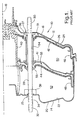
- As shown in FIG. 1, one commonly used type of
brake booster 10, known as a vacuum booster, includes ahousing apparatus 12 having afront housing 14 and arear housing 16, joined together and defining alongitudinal axis 18 of thebooster 10. Thefront housing 14 defines afront wall 20 of thehousing 12 and aninner surface 22 of thefront wall 20. Therear housing 16 defines arear wall 24 of thehousing 12 and aninner surface 26 of therear wall 24. - A
tie rod 28 extends axially throughholes rear walls housing 12. Thetie rod 28 has afirst end 30 engaging therear wall 24 of thehousing 12, and asecond end 32 engaging thefront wall 20 of thehousing 12. Thefirst end 30 of thetie rod 28 includes anannular flange 36 welded or mechanically fastened to theinner surface 26 of therear wall 24, and a threadedsection 34 extending from theannular flange 36, through thehole 27 in therear wall 24, for mounting thebooster 10 on the front of a vehicle dashboard. Thesecond end 32 of thetie rod 28 extends through thehole 25 in thefront wall 20 of thehousing 12, and is also threaded to receive aspecial sealing nut 38 that bears against theinner surface 22 of thefront wall 20. The threaded portion of thesecond end 32 of thetie rod 28 extends outward beyond thefront wall 20 of thebooster 10, for mounting a brake master cylinder to be actuated by thebooster 10. - During assembly of the
booster 10, the position of the sealingnut 38 on the threads at the second end of thetie rod 28 is adjusted so that once the front andrear housings nut 38 will be properly positioned for applying an axially directed force against theinner surface 22 of thefront wall 20 of thehousing 12 to achieve a desired axial distance between the front andrear walls housing 12. Setting the front andrear walls rear housings booster 10, such as thebooster piston 40 and a first and second diaphragm support 42, 44 that move with thepiston 40, so that thebooster 10 can function properly. - The
booster 10, of FIG. 1, is a tandem vacuum brake booster having a primary and asecondary diaphragm divider 41 that separate the interior of thehousing 12 into primary andsecondary vacuum chambers pressure chambers booster 10.Air tubes 54, adapted for sealing engagement with theprimary diaphragm 46 and thedivider 41 of thebooster 10, provide sealed passageways for thetie rod 28 to pass through the primary vacuum andhigh pressure chambers tie rod 28 between the primary vacuum andhigh pressure chambers sliding seal 55, between thesecondary diaphragm 48 and thetie rod 28, precludes leakage around thetie rod 28 between the secondary vacuum andhigh pressure chambers air tubes 54, while adjusting the position of the sealingnut 38 on thetie rod 28, further complicates the process of setting the proper distance between the front andrear walls booster 10. - What is needed, therefore, is an improved method and apparatus for setting and maintaining the axial distance between the front and rear walls of a booster housing in a vacuum booster of the type described above.
- Our invention provides a tie rod apparatus and method for adjusting the axial distance between the front and rear walls of the booster, from outside of the booster, after the booster has been assembled.
- In one form of our invention, a vacuum booster includes a housing having a front housing and a rear housing joined together and defining a longitudinal axis of the booster. The front housing defines a front wall of the housing and an inner surface of the front wall. The rear housing defines a rear wall of the housing and includes a captive nut having threads adapted for threaded engagement with a threaded end of a tie rod. The front and rear walls are spaced an axial distance from one another along the longitudinal axis. A tie rod extends axially through the housing and has a first end engaging the rear wall of the housing and a second end engaging the front wall of the housing. The first end of the tie rod has threads for engaging the threads of the captive nut in the rear wall of the housing. The second end of the tie rod has an axially facing surface thereof for applying an axially directed force against the inner surface front wall of the housing. The axial distance of the housing between the front and rear walls of the housing is adjusted by turning the tie rod, to thread the first end of the tie rod farther in or out of the captive nut.
- In another form of our invention the booster includes internal elements thereof axially separating the interior of the housing into fluid chambers sealed from one another, and the captive nut includes a tube extending axially therefrom along a part of the tie rod into the interior of the housing through one or more of the fluid chambers. The tube has a surface adapted for sealing engagement with the internal elements of the booster.
- The foregoing and other features and advantages of our invention are apparent from the following detailed description of exemplary embodiments, read in conjunction with the accompanying drawing. The detailed description and drawing are merely illustrative of the invention rather than limiting, the scope of the invention being defined by the appended claims and equivalents thereof.
-
- FIG. 1 is a partial cross section of a prior vacuum booster illustrating a prior tie rod apparatus;
- FIG. 2 is a partial cross section of a first exemplary embodiment of our invention having a tie rod including an annular flange bearing against an inner surface of a front wall of the booster housing, and a threaded opposite end of the tie rod engaging a captive nut in a rear wall of the booster housing, so that the axial distance between the front and rear walls may be adjusted after assembly of the booster by turning the tie rod;
- FIG. 3 is a partial cross section of a second exemplary embodiment of our invention having a tie rod including an annular shoulder for clamping a sealing washer against an inner surface of a front wall of the booster housing, and a threaded opposite end of the tie rod engaging a captive nut in a rear wall of the booster housing, so that the axial distance between the front and rear walls may be adjusted after assembly of the booster by turning the tie rod;
- FIG. 4 is a partial cross section of a third exemplary embodiment of our invention, wherein the booster includes internal elements thereof axially separating the interior of the housing into fluid chambers sealed from one another, and the captive nut includes a tube extending axially therefrom along a part of the tie rod into the interior of the housing through one or more of the fluid chambers, with the tube having a surface adapted for sealing engagement with the internal elements of the booster; and
- FIG. 5 is a partial cross section of a booster according to our invention having a return spring not located on the booster axis.
-
- In the various drawing FIGS., similar components and features are identified by the same reference numerals.
- FIG. 2 illustrates a first exemplary embodiment of a
tandem brake booster 110, according to our invention. Thebooster 110 includes ahousing 112 having afront housing 114 and arear housing 116 joined together and defining alongitudinal axis 118 of thebooster 110. Thefront housing 114 defines afront wall 120 of thehousing 110 and aninner surface 122 of thefront wall 120. Therear housing 116 defines arear wall 124 of thehousing 112, and includes one or morecaptive nuts 129 having threads adapted for threaded engagement with a threaded end of atie rod 128. Thecaptive nuts 129 are attached by a process such as welding, brazing, adhesive bonding, or other means of mechanically fastening, to aninside surface 126 of therear wall 124 of thehousing 112. The front andrear walls longitudinal axis 118. - A
tie rod 128 extends axially through thehousing 112 and has afirst end 130 engaging therear wall 124 of thehousing 112. Asecond end 132 of thetie rod 128 engages thefront wall 114 of thehousing 112. Thefirst end 130 of thetie rod 128 has threads for engaging the threads of thecaptive nut 129 in therear wall 124 of thehousing 112. Thesecond end 132 of thetie rod 128 has anannular flange 135 including an axially facingsurface 137 thereof for applying an axially directed force against theinner surface 122front wall 120 of thehousing 112. - Those having skill in the art will recognize that, in contrast to prior boosters of the type described in the Background section above, the axial distance of the
housing 112 between the front andrear walls housing 112 in abooster 110 according to our invention can be adjusted after thebooster 110 is otherwise assembled, by turning thetie rod 128, to thread thefirst end 130 of thetie rod 128 farther in or out of thecaptive nut 126. To facilitate turning thetie rod 128, one or bothends - The threaded
first end 130 of thetie rod 128 extends beyond therear wall 124 of the booster, through thecaptive nut 129 and ahole 127 in therear housing 116, for attaching thebooster 110 to a mounting surface such as the front side of the dashboard of a vehicle. Thesecond end 132 of thetie rod 28 includes a threadedportion 134 extending through ahole 125 in thefront wall 120 and outward beyond thefront wall 120 of thebooster 110, for attaching a brake master cylinder to be actuated by thebooster 110. Aseal 136, in the form of an O-ring or another form of packing, disposed in a trepan groove in theannular flange 135 precludes leakage through thehole 125 around thetie rod 128. A sealant, such as an anaerobic microencapsulated glue is applied to the threads of thefirst end 130 of thetie rod 128 engaging thetie rod 128 for precluding leakage the threads of thetie rod 128 and thecaptive nut 129. - FIG. 3 shows a second embodiment of a
booster 110, according to our invention. The embodiment of FIG. 3 is identical to the embodiment shown in FIG. 2, except for the configuration of thesecond end 132 of thetie rod 128, and the manner in which thesecond end 132 of thetie rod 128 exerts an axial force against theinner surface 122 of thefront wall 120 of thebooster 110. In the second embodiment shown in FIG. 3, the axially facingsurface 137 of thetie rod 128 is provided in the form of a shoulder on thetie rod 128. Theshoulder 137 bears against anannular sealing washer 138, clamped between theshoulder 137 and theinside surface 122 of thefront wall 120. Aseal 136, in the form of an O-ring or other type of packing is disposed in a trepan groove in theannular sealing washer 138 to preclude leakage through thehole 125 around thetie rod 128. - Those having skill in the art will appreciate that by using the
shoulder 137 on thetie rod 128, and theannular sealing washer 138, in conjunction with thecaptive nut 129, manufacturability of thetie rod 128 andbooster 110 are significantly improved, resulting in reductions in manufacturing cost and improvements in quality and reliability of thebooster 110. - FIG. 4 shows a third embodiment of a
booster 110, according to our invention. The embodiment of FIG. 4 is identical to the embodiment shown in FIG. 3, except that thecaptive nut 129 includes atube 156 extending into thebooster 110 and having anouter surface 158 adapted for sealing engagement with internal components of thebooster 110, in a manner precluding leakage along thetie rod 128 between internal fluid chambers within thebooster 110. - The
booster 110, of FIG. 4, is a tandemvacuum brake booster 110 having a primary and asecondary diaphragm divider 141 that separate the interior of thehousing 112 into primary andsecondary vacuum chambers pressure chambers booster 110. - The
outer surface 158 of thetube 156 extending from thecaptive nut 129 is adapted for sealing engagement with theprimary diaphragm 146, and with aseal 160 attached to thedivider 141 of thebooster 110, to provide a sealed passageway for thetie rod 128 to pass through the primary vacuum andhigh pressure chambers tie rod 128 between the primary vacuum andhigh pressure chambers seal 155, between thesecondary diaphragm 148 and thetie rod 128, precludes leakage around thetie rod 128 between the secondary vacuum andhigh pressure chambers - Those having skill in the art will appreciate that by making the
tube 156 integral with thecaptive nut 129, as shown in FIG. 4, theseparate air tubes 54 used in the prior art booster shown in FIG. 1 can be eliminated to reduce cost and facilitate manufacturability and reliability of thebooster 110. It should be noted, however, that aspects of our invention may be utilized inboosters 110 havingair tubes 54 separate from thecaptive nut 129, as shown in the embodiments of FIGS. 2 and 3. It should be further noted that theair tube 156 extending from thecaptive nut 129 may be used with the tie rod embodiment shown in FIG. 2, or other tie rod embodiments within the scope of the appended claims. - While the embodiments of our invention disclosed herein are presently considered to be preferred, various changes and modifications can be made without departing from the spirit and scope of the invention. The various elements and aspects of our invention may also be used independently from one another, or in different combinations than are described above and in the drawing with regard to the exemplary embodiment. For example, in other embodiments of our invention, more than one
tie rod 128, andcaptive nut 129, with or without thetube 156 extending from thecaptive nut 129, may be utilized. Also, as shown in FIG. 5, our invention may be practiced inboosters 110 having one or more return springs 161 located and acting parallel to thebooster axis 118, rather than a more traditional barrel shapedpiston return spring 162 disposed about thebooster axis 118, as shown in the embodiments of FIGS. 1-4. - The scope of the invention is indicated in the appended claims. We intend that all changes or modifications within the meaning and range of equivalents are embraced by the claims.
Claims (20)
- A vacuum booster 110 comprising:a housing 112 having a front housing 114 and a rear housing 116 thereof joined together and defining a longitudinal axis 118 of the booster 110, the front housing 114 defining a front wall 112 of the housing 110 and an inner surface 122 of the front wall 120, the rear housing 116 defining a rear wall 124 of the housing 112 and including a captive nut 129 having threads adapted for threaded engagement with a threaded end 130 of a tie rod 128, the front and rear walls 120, 124 spaced an axial distance from one another along the longitudinal axis 118; anda tie rod 132 extending axially through the housing 112 and having a first end 130 engaging the rear wall 124 of the housing 112 and a second end 130 engaging the front wall 120 of the housing 112, the first end 130 of the tie rod 128 having threads for engaging the threads of the captive nut 129 in the rear wall 124 of the housing 112, the second end 132 of the tie rod 128 having an axially facing surface 137 thereof for applying an axially directed force against the inner surface122 of the front wall 120 of the housing 112, whereby the axial distance of the housing between the front and rear walls 120, 124 of the housing 112 is adjustable by turning the tie rod 128 for threading the first end 130 of the tie rod 128 farther in or out of the captive nut 129.
- The booster 110 of claim 1 wherein the first end 130 of the tie rod 128 extends through the captive nut 129 and outward from the rear wall 124 of the housing 112 for mounting the booster 110 to a surface.
- The booster 110 of claim 1 wherein the axial distance of the housing between the front and rear walls 120, 124 of the housing 112 is adjustable from outside of the housing 112 by turning the tie rod 128 for threading the first end 130 of the tie rod 128 farther in or out of the captive nut 129.
- The booster 110 of claim 3 wherein the second end 132 of the tie rod 128 extends through the front wall 120 of the housing 112, and is adapted for engaging a tool for turning the tie rod 128.
- The booster 110 of claim 1 wherein the second end 132 of the tie rod 128 includes a flange 135 extending radially outward therefrom defining the axial facing surface 137 of the tie rod 128.
- The booster 110 of claim 1 further including a seal 136 disposed about the second end 132 of the tie rod 128 for resisting air flow between the tie rod 128 and the front wall 120 of the housing 110.
- The booster 110 of claim 6 further including a washer 138 disposed between the axially facing surface of the second end 132 of the tie rod 128 and the inner surface 122 of the front wall 120 of the housing 110.
- The booster 110 of claim 1 wherein:the booster 110 includes internal elements 151, 146, 141, 160, 144, 148, 155 thereof axially separating the interior of the housing 112 into fluid chambers 150, 152 sealed from one another; andthe captive nut 129 includes a tube 156 extending axially therefrom along a part of the tie rod 128 into the interior of the housing 112 through one or more of the fluid chambers 150, 152, the tube 156 having a surface 158 adapted for sealing engagement with the internal elements 146, 160 of the booster 110.
- The booster 110 of claim 1 including a sealant between the first end of the tie rod 128 and the captive nut 129.
- A vacuum booster 110 comprising:a housing 112 having a front housing 114 and a rear housing 116 thereof joined together and defining a longitudinal axis 118 of the booster 110, the front housing 114 defining a front wall 120 of the housing 112 and an inner surface 122 of the front wall 120, the rear housing 114 defining a rear wall 124 of the housing 112 and including a captive nut 129 having threads adapted for threaded engagement with a threaded end 130 of a tie rod 128, the front and rear walls 120, 124 spaced an axial distance from one another along the longitudinal axis 118;a tie rod 128 extending axially through the housing 112 and having a first end 130 engaging the rear wall 124 of the housing 112 and a second end 132 engaging the front wall 120 of the housing 112, the first end 130 of the tie rod 128 having threads for engaging the threads of the captive nut 129 in the rear wall 124 of the housing 112, the second end 132 of the tie rod 128 having an axially facing surface 137 thereof for applying an axially directed force against the inner surface 122 of the front wall 120 of the housing 112, whereby the axial distance of the housing 112 between the front and rear walls 120, 124 of the housing 112 is adjustable by turning the tie rod 128 for threading the first end 130 of the tie rod 128 farther in or out of the captive nut 129;the booster 110 further including internal elements thereof 151, 146, 141, 160, 144, 148, 155 axially separating the interior of the housing 112 into fluid chambers 150, 152 sealed from one another; andthe captive nut 129 including a tube 156 extending axially therefrom along a part of the tie rod 128 into the interior of the housing 112 through one or more of the fluid chambers 150, 152, the tube 156 having a surface 158 adapted for sealing engagement with the internal elements 151, 146, 141, 160, 144, 148, 155 of the booster.
- The booster 110 of claim 10 wherein the first end 130 of the tie rod 128 extends through the captive nut 129 and outward from the rear wall 124 of the housing 112 for mounting the booster 110 to a surface.
- The booster 110 of claim 10 wherein the axial distance of the housing 112 between the front and rear walls 120, 124 of the housing 112 is adjustable from outside of the housing 110 by turning the tie rod 128 for threading the first end 130 of the tie rod 128 farther in or out of the captive nut 129.
- The booster 110 of claim 12 wherein the second end 132 of the tie rod 128 extends through the front wall 120 of the housing 112, and is adapted for engaging a tool for turning the tie rod 128.
- The booster 110 of claim 10 wherein the second end 132 of the tie rod 128 includes a flange 135 extending radially outward therefrom defining the axial facing surface 137 of the tie rod 128.
- The booster 110 of claim 10 further including a seal 136 disposed about the second end 132 of the tie rod 128 for resisting air flow between the tie rod 128 and the front wall 120 of the housing 110.
- The booster 110 of claim 15 further including a washer 138 disposed between the axially facing surface 137 of the second end 1332 of the tie rod 128 and the inner surface 122 of the front wall 120 of the housing 112.
- The booster 110 of claim 10 including a sealant between the first end 130 of the tie rod 128 and the captive nut 129.
- A method for manufacturing a vacuum booster 110, the method comprising:providing a housing 112 and a tie rod 128;the housing 112 having a front housing 114 and a rear housing 116 thereof joined together and defining a longitudinal axis 118 of the booster 110, the front housing 114 defining a front wall 120 of the housing 112 and an inner surface 122 of the front wall 120, the rear housing 116 defining a rear wall 124 of the housing 112 and including a captive nut 129 having threads adapted for threaded engagement with a threaded end 130 of a tie rod 128, the front and rear walls 120, 124 spaced an axial distance from one another along the longitudinal axis 118;the tie rod 128 extending axially through the housing 112 and having a first end 130 engaging the rear wall 124 of the housing 112 and a second end 132 engaging the front wall 120 of the housing 112, the first end 130 of the tie rod 128 having threads for engaging the threads of the captive nut 129 in the rear wall 124 of the housing 112, the second end 132 of the tie rod 128 having an axially facing surface 137 thereof for applying an axially directed force against the inner surface 122 of the front wall 120 of the housing 112; andadjusting the axial distance of the housing 112 between the front and rear walls 120, 124 of the housing 112 by turning the tie rod 128 to thread the first end of the tie rod 128 farther in or out of the captive nut 129.
- The method of claim 18 further comprising turning the tie rod 128 from outside of the housing 112, after the booster 110 is otherwise completely assembled.
- The method of claim 18 further comprising:configuring the second end 132 of the tie rod 128 to extend through and beyond the front wall 120 of the housing 112 and to engage a tool for turning the tie rod 128;engaging the second end 132 of the tie rod 128 with a tool; and turning the tie rod 128.
Applications Claiming Priority (2)
| Application Number | Priority Date | Filing Date | Title |
|---|---|---|---|
| US292733 | 1999-04-15 | ||
| US10/292,733 US6772674B2 (en) | 2002-11-12 | 2002-11-12 | Tie rod apparatus and method for assembling a vacuum booster |
Publications (2)
| Publication Number | Publication Date |
|---|---|
| EP1419948A1 true EP1419948A1 (en) | 2004-05-19 |
| EP1419948B1 EP1419948B1 (en) | 2011-12-07 |
Family
ID=32176165
Family Applications (1)
| Application Number | Title | Priority Date | Filing Date |
|---|---|---|---|
| EP03078208A Expired - Lifetime EP1419948B1 (en) | 2002-11-12 | 2003-10-10 | Tie rod apparatus and method for assembling a vacuum booster |
Country Status (2)
| Country | Link |
|---|---|
| US (1) | US6772674B2 (en) |
| EP (1) | EP1419948B1 (en) |
Families Citing this family (4)
| Publication number | Priority date | Publication date | Assignee | Title |
|---|---|---|---|---|
| JP4461320B2 (en) * | 2003-11-28 | 2010-05-12 | 日立オートモティブシステムズ株式会社 | Pneumatic booster |
| FR2902736B1 (en) * | 2006-06-21 | 2009-03-27 | Bosch Gmbh Robert | TENSION SERVOMOTOR COMPRISING A REINFORCED SEAL RING. |
| DE102007049960A1 (en) * | 2007-10-18 | 2009-04-23 | Lucas Automotive Gmbh | Vacuum brake booster for a motor vehicle brake system |
| DE102015217520A1 (en) * | 2015-09-14 | 2017-03-16 | Robert Bosch Gmbh | Electromechanical brake booster and brake system |
Citations (4)
| Publication number | Priority date | Publication date | Assignee | Title |
|---|---|---|---|---|
| US5487327A (en) * | 1993-09-24 | 1996-01-30 | Lucas Industries Public Limited Company | Booster housing, especially for vehicle brake systems, and method of assembling such as booster housing |
| EP0760319A1 (en) * | 1995-09-01 | 1997-03-05 | LUCAS INDUSTRIES public limited company | Brake force booster and master cylinder unit with connection struts |
| WO2000061416A1 (en) * | 1999-04-09 | 2000-10-19 | Continental Teves Ag & Co. Ohg | Pneumatic brake booster |
| DE10136379C1 (en) * | 2001-07-26 | 2002-12-05 | Lucas Automotive Gmbh | Tandem brake amplifier for vehicle braking system has connection between working chambers of brake amplification units provided by coaxial sleeve around clamp bolt for brake amplifier housing |
Family Cites Families (6)
| Publication number | Priority date | Publication date | Assignee | Title |
|---|---|---|---|---|
| JPS5923653Y2 (en) * | 1979-07-20 | 1984-07-13 | トキコ株式会社 | pneumatic booster |
| FR2727922A1 (en) * | 1994-12-09 | 1996-06-14 | Alliedsignal Europ Services | DEFORMABLE ENCLOSURE SERVOMOTOR |
| US6164183A (en) | 1999-02-10 | 2000-12-26 | Delphi Technologies, Inc. | Brake booster with alternate activation by rotary electric motor |
| US6209442B1 (en) | 1999-08-16 | 2001-04-03 | Delphi Technologies, Inc. | Brake booster with compressible air valve for braking speed of application enhancement |
| US6374721B1 (en) | 2000-08-08 | 2002-04-23 | Delphi Technologies, Inc. | Vacuum booster with retaining mechanism for cylinder cap |
| US6637837B2 (en) | 2001-12-20 | 2003-10-28 | Delphi Technologies, Inc. | Vacuum booster air intake via engine compartment breather passage |
-
2002
- 2002-11-12 US US10/292,733 patent/US6772674B2/en not_active Expired - Lifetime
-
2003
- 2003-10-10 EP EP03078208A patent/EP1419948B1/en not_active Expired - Lifetime
Patent Citations (4)
| Publication number | Priority date | Publication date | Assignee | Title |
|---|---|---|---|---|
| US5487327A (en) * | 1993-09-24 | 1996-01-30 | Lucas Industries Public Limited Company | Booster housing, especially for vehicle brake systems, and method of assembling such as booster housing |
| EP0760319A1 (en) * | 1995-09-01 | 1997-03-05 | LUCAS INDUSTRIES public limited company | Brake force booster and master cylinder unit with connection struts |
| WO2000061416A1 (en) * | 1999-04-09 | 2000-10-19 | Continental Teves Ag & Co. Ohg | Pneumatic brake booster |
| DE10136379C1 (en) * | 2001-07-26 | 2002-12-05 | Lucas Automotive Gmbh | Tandem brake amplifier for vehicle braking system has connection between working chambers of brake amplification units provided by coaxial sleeve around clamp bolt for brake amplifier housing |
Also Published As
| Publication number | Publication date |
|---|---|
| US20040089149A1 (en) | 2004-05-13 |
| US6772674B2 (en) | 2004-08-10 |
| EP1419948B1 (en) | 2011-12-07 |
Similar Documents
| Publication | Publication Date | Title |
|---|---|---|
| US5410880A (en) | Actuator unit for motor vehicle brakes | |
| US6623048B2 (en) | Apparatus and method of attaching a tube member to a housing of a vacuum brake booster | |
| AU673303B2 (en) | Tamper-resistant brake actuator | |
| US20020170427A1 (en) | Apparatus and method of attaching a connecting member and a tube member to a housing of a vacuum brake booster | |
| US5655431A (en) | Spring brake actuator, caging bolt assembly therefor, and method of assembly thereof | |
| US6772674B2 (en) | Tie rod apparatus and method for assembling a vacuum booster | |
| JP2003508297A (en) | Brake booster with wall mounting means | |
| JP4411031B2 (en) | Pneumatic brake booster and system with a master cylinder attached to such a booster | |
| US7331275B2 (en) | Brake booster with deformationally sealed passage and method of manufacture | |
| US6651548B1 (en) | Pneumatic brake booster | |
| US9663087B2 (en) | Vacuum brake booster having tubes through which attachment screws pass and method for realizing same | |
| US4416191A (en) | Vacuum booster device | |
| US6223647B1 (en) | Brake actuator and method of forming same | |
| US20050087067A1 (en) | Vacuum booster with self-locking diaphragm support | |
| US6561077B2 (en) | System and process for assembling a tube in a connecting element, and servomotor housing including such a system | |
| EP0765789B1 (en) | Improvements in pneumatically-operated boosters for vehicle braking systems | |
| US6453670B1 (en) | Two-piece stationary seal master cylinder | |
| EP0665793B1 (en) | Seal for mounting flange of a master cylinder | |
| US6360778B1 (en) | Modulator body and fluid accumulator for use in vehicle brake system | |
| EP0972691B1 (en) | A brake booster | |
| US20050074353A1 (en) | Diaphragm-less vacuum booster | |
| GB2122705A (en) | Pneumatic servo booster | |
| JP4293769B2 (en) | Brake pipe and fittings | |
| AU700359B2 (en) | Spring brake actuator, caging bolt assembly therefor, and method of assembly thereof | |
| KR20000055502A (en) | Booster for vehicle |
Legal Events
| Date | Code | Title | Description |
|---|---|---|---|
| PUAI | Public reference made under article 153(3) epc to a published international application that has entered the european phase |
Free format text: ORIGINAL CODE: 0009012 |
|
| AK | Designated contracting states |
Kind code of ref document: A1 Designated state(s): AT BE BG CH CY CZ DE DK EE ES FI FR GB GR HU IE IT LI LU MC NL PT RO SE SI SK TR |
|
| AX | Request for extension of the european patent |
Extension state: AL LT LV MK |
|
| 17P | Request for examination filed |
Effective date: 20041119 |
|
| AKX | Designation fees paid |
Designated state(s): DE FR GB |
|
| 17Q | First examination report despatched |
Effective date: 20090605 |
|
| GRAP | Despatch of communication of intention to grant a patent |
Free format text: ORIGINAL CODE: EPIDOSNIGR1 |
|
| RAP1 | Party data changed (applicant data changed or rights of an application transferred) |
Owner name: BWI COMPANY LIMITED S.A. |
|
| GRAS | Grant fee paid |
Free format text: ORIGINAL CODE: EPIDOSNIGR3 |
|
| GRAA | (expected) grant |
Free format text: ORIGINAL CODE: 0009210 |
|
| AK | Designated contracting states |
Kind code of ref document: B1 Designated state(s): DE FR GB |
|
| REG | Reference to a national code |
Ref country code: GB Ref legal event code: FG4D |
|
| REG | Reference to a national code |
Ref country code: DE Ref legal event code: R096 Ref document number: 60339320 Country of ref document: DE Effective date: 20120216 |
|
| PLBE | No opposition filed within time limit |
Free format text: ORIGINAL CODE: 0009261 |
|
| STAA | Information on the status of an ep patent application or granted ep patent |
Free format text: STATUS: NO OPPOSITION FILED WITHIN TIME LIMIT |
|
| 26N | No opposition filed |
Effective date: 20120910 |
|
| REG | Reference to a national code |
Ref country code: DE Ref legal event code: R097 Ref document number: 60339320 Country of ref document: DE Effective date: 20120910 |
|
| GBPC | Gb: european patent ceased through non-payment of renewal fee |
Effective date: 20121010 |
|
| PG25 | Lapsed in a contracting state [announced via postgrant information from national office to epo] |
Ref country code: GB Free format text: LAPSE BECAUSE OF NON-PAYMENT OF DUE FEES Effective date: 20121010 |
|
| PGFP | Annual fee paid to national office [announced via postgrant information from national office to epo] |
Ref country code: FR Payment date: 20131009 Year of fee payment: 11 |
|
| REG | Reference to a national code |
Ref country code: FR Ref legal event code: ST Effective date: 20150630 |
|
| PG25 | Lapsed in a contracting state [announced via postgrant information from national office to epo] |
Ref country code: FR Free format text: LAPSE BECAUSE OF NON-PAYMENT OF DUE FEES Effective date: 20141031 |
|
| PGFP | Annual fee paid to national office [announced via postgrant information from national office to epo] |
Ref country code: DE Payment date: 20180925 Year of fee payment: 16 |
|
| REG | Reference to a national code |
Ref country code: DE Ref legal event code: R119 Ref document number: 60339320 Country of ref document: DE |
|
| PG25 | Lapsed in a contracting state [announced via postgrant information from national office to epo] |
Ref country code: DE Free format text: LAPSE BECAUSE OF NON-PAYMENT OF DUE FEES Effective date: 20200501 |