EP1418398A1 - Shape measuring device - Google Patents
Shape measuring device Download PDFInfo
- Publication number
- EP1418398A1 EP1418398A1 EP02746070A EP02746070A EP1418398A1 EP 1418398 A1 EP1418398 A1 EP 1418398A1 EP 02746070 A EP02746070 A EP 02746070A EP 02746070 A EP02746070 A EP 02746070A EP 1418398 A1 EP1418398 A1 EP 1418398A1
- Authority
- EP
- European Patent Office
- Prior art keywords
- measuring
- guide rail
- shape
- measuring head
- foot
- Prior art date
- Legal status (The legal status is an assumption and is not a legal conclusion. Google has not performed a legal analysis and makes no representation as to the accuracy of the status listed.)
- Withdrawn
Links
- 238000005259 measurement Methods 0.000 claims abstract description 92
- 238000003384 imaging method Methods 0.000 claims description 3
- 230000001678 irradiating effect Effects 0.000 claims description 2
- 210000002683 foot Anatomy 0.000 description 72
- 238000000034 method Methods 0.000 description 14
- 239000011159 matrix material Substances 0.000 description 12
- 230000003287 optical effect Effects 0.000 description 5
- 210000003423 ankle Anatomy 0.000 description 4
- 239000003550 marker Substances 0.000 description 4
- 102100039216 Dolichyl-diphosphooligosaccharide-protein glycosyltransferase subunit 2 Human genes 0.000 description 3
- 101000670093 Homo sapiens Dolichyl-diphosphooligosaccharide-protein glycosyltransferase subunit 2 Proteins 0.000 description 3
- 101100479019 Encephalitozoon intestinalis SWP2 gene Proteins 0.000 description 1
- 101100519877 Schizosaccharomyces pombe (strain 972 / ATCC 24843) phf2 gene Proteins 0.000 description 1
- 238000006243 chemical reaction Methods 0.000 description 1
- 238000006073 displacement reaction Methods 0.000 description 1
- 230000000694 effects Effects 0.000 description 1
- 230000005484 gravity Effects 0.000 description 1
Images


Classifications
-
- A—HUMAN NECESSITIES
- A43—FOOTWEAR
- A43D—MACHINES, TOOLS, EQUIPMENT OR METHODS FOR MANUFACTURING OR REPAIRING FOOTWEAR
- A43D1/00—Foot or last measuring devices; Measuring devices for shoe parts
- A43D1/02—Foot-measuring devices
- A43D1/025—Foot-measuring devices comprising optical means, e.g. mirrors, photo-electric cells, for measuring or inspecting feet
-
- A—HUMAN NECESSITIES
- A43—FOOTWEAR
- A43D—MACHINES, TOOLS, EQUIPMENT OR METHODS FOR MANUFACTURING OR REPAIRING FOOTWEAR
- A43D1/00—Foot or last measuring devices; Measuring devices for shoe parts
- A43D1/06—Measuring devices for the inside measure of shoes, for the height of heels, or for the arrangement of heels
-
- A—HUMAN NECESSITIES
- A61—MEDICAL OR VETERINARY SCIENCE; HYGIENE
- A61B—DIAGNOSIS; SURGERY; IDENTIFICATION
- A61B5/00—Measuring for diagnostic purposes; Identification of persons
- A61B5/103—Measuring devices for testing the shape, pattern, colour, size or movement of the body or parts thereof, for diagnostic purposes
- A61B5/107—Measuring physical dimensions, e.g. size of the entire body or parts thereof
- A61B5/1074—Foot measuring devices
-
- G—PHYSICS
- G01—MEASURING; TESTING
- G01B—MEASURING LENGTH, THICKNESS OR SIMILAR LINEAR DIMENSIONS; MEASURING ANGLES; MEASURING AREAS; MEASURING IRREGULARITIES OF SURFACES OR CONTOURS
- G01B11/00—Measuring arrangements characterised by the use of optical techniques
- G01B11/24—Measuring arrangements characterised by the use of optical techniques for measuring contours or curvatures
Definitions
- the present invention relates to a shape measuring device comprising a measuring head for measuring the shape of an object to be measured at a plurality of measuring positions on a guide rail while moving along the guide rail, and more particularly, to a shape measuring device suited to measure the shape of a foot.
- an active stereo-type shape measuring device that irradiates a beam of spot tight, slit light, or the like onto an object to be measured and restores from the position of a light image observed on a surface of the object to be measured its three-dimensional shape.
- An example of such a shape measuring device is one that scans spot light or slit light by a rotary mirror in order to measure the shape of an object to be measured.
- a magazine “Measurement and Control" (1999 Vol. 38 No. 4 P285-288) describes a system for measuring the shape of a foot using such a shape measuring device.
- one shape measuring device can measure only the shape of a portion observed from the device and cannot measure the shape of a portion concealed on the opposite side thereof, for example. Therefore, 12 shape measuring devices are arranged around the foot, and the results of the measurement by the 12 shape measuring devices are synthesized on a computer, thereby measuring the shape of the whole of the foot.
- the plurality of shape measuring devices are arranged around the foot. Therefore, not only the problem that the system increases in size and increases in cost but also the problem that it is difficult to synthesize the results of measurement by the plurality of shape measuring devices with high precision arises.
- a shape measuring device that measures the shape of the whole of an object to be measured by a measuring person gripping a measuring head and moving the measuring head around the object to be measured to make measurement.
- a plurality of markers attached to the measuring head are imaged from above by two cameras, thereby measuring the position and the direction of the measuring head.
- a guide rail in an elliptical shape in such a shape that two sides extending along the lengths of opposed two semicircles are connected to each other
- a measuring head is moved along the guide rail.
- the guide rail for moving the measuring head is made to have a loop shape such as a circular shape or an elliptical. shape, as described above, the size of an object to be measured whose shape can be measured is limited by the size of the guide rail. That is, in a case where the object to be measured is even slightly larger than a measurable range including the moving margins of the guide rail and the measuring head, the shape cannot be measured. Particularly, in a case where the shape of a foot is measured, the size of the foot differs among individuals, and differs depending on races. For example, the feet of the Westerner are larger than those of the Japanese. Therefore, the foot may not, in some cases, be arranged inside the guide rail in a loop shape.
- the present invention has been made in view of such a problem and has for its object to provide a shape measuring device capable of making the size of an object to be measured which can be measured have a degree of freedom.
- an object is to provide a shape measuring device that can measure the shape of the foot irrespective of the difference in the size of the foot depending on adults or children, sex, races, or the like.
- a shape measuring device comprising a measuring head for measuring the shape of an object to be measured at a plurality of measuring positions on a guide rail while moving along the guide rail
- a shape measuring device is characterized in that the guide rail is in a U shape, and the measuring head makes measurement for measuring the shape of the object to be measured which is arranged inside the U-shaped guide rail at the plurality of measuring positions on the guide rail while moving along the guide rail.
- the direction in which the foot is arranged is determined such that. a direction from inside a curved portion of the U-shaped guide rail toward an opened portion thereof is a direction along the length of the foot.
- the measuring head makes measurement for measuring the shape of a foot arranged inside the U-shaped guide rail at the plurality of measuring positions on the guide rail while moving along the guide rail.
- the measuring head used as the measuring head is one comprising a light source for irradiating a light beam toward the foot arranged inside the U-shaped guide rail and a camera for imaging the light beam irradiated onto the foot by the light source.
- the coordinates of the light beam imaged by the camera are calculated at the plurality of measuring positions on the U-shaped guide rail so that the shape of the foot arranged inside the guide rail is measured.
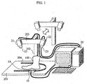
- Fig. 1 illustrates the schematic configuration of a shape measuring device according to an embodiment of the present invention.
- a U-shaped guide rail 204 is fixed to a measuring stand 201, and a foot 100 serving as an object to be measured is put on an area enclosed by the guide rail 204.
- a support 202 which is detachable from the stand 201 is attached to the stand 201, and a horizontal bar 203 is attached to its upper part.
- the shape measuring device comprises a measuring head 10 which is moved on the guide rail 204 by a measuring person, stereo cameras 21 and 22 attached to both ends of the horizontal bar 203, and a control device 30 composed of a personal computer for carrying out their control, various types of operations, and the like.
- a band-pass filter 23 which selectively transmits frequency bands of light beams emitted by six markers 14 shown in Fig. 2 is attached to an imaging lens of each of the stereo cameras 21 and 22.
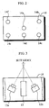
- Figs. 2 and 3 illustrate the schematic configuration of the measuring head 10.
- the measuring head 10 comprises a casing in a rectangular parallelepiped shape and opened forward, two CCD cameras 12a and 12b accommodated in the casing, and a slight light source 13 so constructed that laser light is scanned upward and downward to form slit light. Further, the measuring head 10 comprises a driving mechanism (not shown) for moving in a clockwise direction or in a counterclockwise direction along the guide rail 204.
- the marker 14 comprising six LED light sources 14a and 14f is provided on an upper surface of the casing of the measuring head 10.
- the arrangement of the six LED light sources constituting the marker 14 is not point-symmetrical but line-symmetrical with respect to the center line of the measuring head 10 in order to specify the direction of the measuring head 10.
- the five LED light sources 14b, 14c, 14d, 14e, and 14f are arranged so as to take a rectangle on the upper surface of the casing, and the one LED light source 14a is arranged at the position of its center of gravity.
- LED light sources may be sufficient as the marker 14 in order to measure the position and the direction of the measuring head 10 in a three-dimensional space
- four or more LED light sources are used to improve the measuring precision of the position and the direction of the measuring head 10 in a least square manner.
- the measuring head 10 is attached so as to be movable along the guide rail 204 by a supporting mechanism (not shown). Further, the measuring head 10 comprises an encoder (not shown) for detecting the position of the measuring head 10 using as a basis a predetermined position on the guide rail 204. An output of the encoder 10 is inputted to the control device 30.
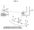
- the coordinates of a certain measuring point A are measured using the measuring head 10 which is moved on the guide rail 204 by the measuring person.
- the measured coordinates are represented by coordinates (x, y, z) in a coordinate system using a measuring head as a basis (centered with respect to a measuring head).
- the coordinate system is a coordinate system which moves as the measuring head 10 moves.
- the shape of the object to be measured 100 is represented by a fixed coordinate system, and the coordinate system is referred to as a world coordinate system.
- the coordinates, in the world coordinate system, of a measuring point measured by the measuring head 10 are taken as (X, Y, Z).
- the shape of the object to be measured 100 must be described by the world coordinate system.
- the coordinates (x, y, z), in the coordinate system using a measuring head as a basis, of the measuring point A measured by the measuring head 10 are converted into the coordinates (X, Y, Z) in the world coordinate system.
- the conversion is performed on the basis of the following equation (1) using a rotating matrix R and a translation vector t which represent the movement of the measuring head 10:
- the coordinates (x, y, z) in the coordinate system using a measuring head as a basis can be converted into the coordinates (X, Y, Z) in the world coordinate system by finding the position and the direction of the measuring head 10 in the world coordinate system as the rotating matrix R and the translation vector t.
- the measurement of the shape by the shape measuring device is made by the following procedure for processing.
- preliminary processing (the following first and second steps) is performed before making actual measurement.
- information related to each or measuring positions of the measuring head 10 in the world coordinate system is stored in a memory (not shown) carried on the control device 30 in correspondence with the output value of the encoder at the measuring position.
- Information related to each of the measuring positions of the measuring head 10 in the world coordinate system is the rotating matrix R and the translation vector t which represent the movement of the measuring head 10 in the world coordinate system.
- the coordinates, in the world coordinate system, of each of the markers 14 provided in the measuring head 10 are measured by the stereo cameras 21 and 22. Since the position measuring method has been well known as a stereo method, the description thereof is omitted.
- the coordinates, in the coordinate system using a measuring head as a basis, of each of the LED light sources 14a to 14f constituting the marker 14 are then respectively taken as (xi, yi, zi), and the coordinates, in the world coordinate system, of each of the LED light sources 14a to 14f measured by the stereo cameras 21 and 22 are respectively taken as (Xi, Yi, Zi), where i is 1, 2, ... 6.
- the coordinates (xi, yi, zi) , in the coordinate system using a measuring head as a basis, of each of the LED light sources 14a to 14f have already been known.
- the rotating matrix R and the translation vector t which represent the movement of the measuring head 10 are found as a matrix R and a vector t which satisfy the following equation (2).
- the found matrix R and vector t are stored in the memory in correspondence with the output value of the encoder at the measuring position of the measuring head 10.
- the measuring head 10 is moved along the guide rail 204, and the above-mentioned processing is repeatedly performed with respect to all the measuring positions on the guide vail 204, to produce a table representing a correspondence between the output value of the encoder and the rotating matrix and the translation vector t at the position.
- the support 202 for supporting the stereo cameras 21 and 22 is removed from the stand 201. In such a manner, the object to be measured 100 is actually measured after the preliminary processing is completed. Description is now made of a case where the object to be measured is a human foot 100.
- the coordinates of a measuring point on the object to be measured (foot) 100 in the coordinate system using a measuring head as a basis are found using the measuring head 10.
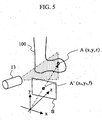
- Fig. 5 illustrates a method of measuring the position of a measuring point by the measuring head 10.
- the coordinate system using a measuring head as a basis is a coordinate system having the optical center of the CCD camera 12 as its origin, having the direction of the optical axis as its z-axis, the horizontal direction of the CCD camera 12 as its x-axis, and the vertical direction of the CCD camera 12 as its y-axis.
- a method of measuring a position by the measuring head 10 is itself a known measuring method called a light-section method.
- a predetermined point on a line irradiated with the slit light from the slit light source 13 on a surface of the object to be measured 100 is taken as a measuring point A.
- the coordinates, in the coordinate system using a measuring head as a basis, of the measuring point A are taken as (x, y, z)
- the coordinates of an observing point A' corresponding to the measuring point A on the image surface S are taken as (xs, ys, f)
- f has already been known as the focal length of the CCD camera 12, and (xs, ys) are found from the pixel position of the slit light observed on the image surface.
- the processing is performed by the control device 30 on the basis of an output of the CCD camera 12.
- the rotating matrix R and the translation vector t which correspond to each other are read out of the memory in the control device 30 on the basis of the output of the encoder.
- the coordinates (x, y, z), in the coordinate system using a measuring head as a basis, which is found in the third step, of the measuring point on the object to be measured (foot) 100 are converted into the coordinates (X, Y, Z) in the world coordinate system on the basis of the rotating matrix R and the translation vector t which are read out in the fourth step.
- the measuring head 10 is moved along the. guide rail 204, and the processing in the third to fifth steps is repeated with respect to all the measuring positions on the guide rail 204, thereby finding the shape of the object to be measured (foot) 100 as a set of the coordinates (X, Y, Z), in the world coordinate system, of the measuring point obtained each time.
- the coordinates, in the coordinate system using a measuring head as a basis, of the measuring point obtained using the measuring head 10 are converted into the coordinates in the world coordinate system using table data representing a correspondence between the position on the guide rail 204 of the measuring head 10 and the rotating matrix R and the translation vector t at the position. Accordingly, the necessity of the stereo cameras 21 and 22 is eliminated in making shape measurement, and a user can measure the shape of the object to be measured without being conscious of the field of view of a.camera and the tangle of a code, thereby making it possible to provide higher usability.
- the foot is placed inside the guide rail 204.
- the foot is placed with the central position of a circular arc portion of the.
- U-shaped guide rail 204 taken as the center of its heel. To thus place the foot makes it possible to measure, with respect to feet of various sizes (various types of feet having different lengths), the respective shapes of the feet.
- Fig. 6 illustrates in a time series manner the movement of the measuring head 10 in a case where the right foot 100 is placed inside the U-shaped guide rail 204 to measure the shape of the right foot.
- the 10a indicates a case where the measuring head 10 is at a left home position LHP.
- the measuring head 10 is moved in a counterclockwise direction along the guide rail 204 from the left home position LHP.
- 10b indicates a case where the measuring head 10 is at the position where the toe of the right foot 100 is detected.
- 10c indicates a case where the measuring head 10 is at a camera switching position for a right foot SWP1 set near the right ankle of the right foot 100.
- 10d indicates a case where the measuring head 10 is at the position where the measurement is terminated, which is calculated from the position where the toe is detected, indicated by 10a.
- 10e indicates a case where the measuring head 10 is at a right home position RHP.
- Fig. 7 shows the procedure for control processing of the measuring head 10 by the control device 300.
- processing in the steps S1 to S4 is performed as measurement preparation processing.
- the direction of measurement is first acquired (step S1). That is, the direction of movement of the measuring head 10 (a clockwise direction or a counterclockwise direction) is acquired.
- the direction of subsequent measurement is stored in the final step S15, described later, so that the stored direction of subsequent measurement is acquired as the current direction of measurement.
- the direction of subsequent measurement is not stored, the direction of measurement in which the movement is started is automatically selected on the basis of a home position near the current position of the measuring head 10.
- the counterclockwise direction is selected as the direction of measurement when the measuring head 10 is at a position near the left home position LHP
- the clockwise direction is selected as the direction of measurement when the measuring head 10 is at a position near the right home position RHP.
- the measuring head 10 is at the position near the left home position LHP, and the counterclockwise direction is acquired as the direction of measurement.
- step S2 The results of selection as to whether the foot to be measured is a right foot or a left foot is then acquired (step S2). Selection as to whether the foot to be measured is a right foot or a left foot is made by an operator performing a predetermined selection operation on a display with respect to the control device 300. In this example, it is assumed that the right foot is selected, as in the example shown in Fig. 6.
- the measuring head 10 is then moved to the home position (HP) determined by the direction of measurement (step S3). That is, the measuring head 10 is moved to the left home position LHP (the position indicated by 10a in Fig. 6) when the direction of measurement is the counterclockwise direction, while being moved to the right home position RHP (the position indicated by 10e in Fig. 6) when the direction of measurement is the clockwise direction. In this example, it is assumed that the measuring head 10 is moved to the left home position LHP because the direction of measurement is the counterclockwise direction.
- the camera first used for the measurement is selected on the basis of the direction of measurement (step S4). That is, out of the two cameras 12a and 12b, the camera positioned on the rear side in the direction of measurement is selected.
- the camera 12a is selected when the direction of movement is the counterclockwise direction
- the camera 12b is selected when the direction of measurement is the clockwise direction.
- the camera 12a is selected as the camera first used for measurement. Consequently, the camera which more easily detects the toe, that is, the camera 12a positioned on the rear side in the direction of movement is selected as the camera first used for measurement, as indicated by 10b in Fig. 6.
- toe search processing in the steps S5 to S7 is performed.
- the toe search processing is processing for detecting the toe of the foot. In the toe search processing, shape measurement is not made.
- step S5 measurement for detecting the toe (the tip of the foot) is first started by increasing the movement speed of the measuring head 10 (step S5). That is, measurement for detecting the toe is made while moving the measuring head 10 at high speed, as indicated by an arrow V1 in Fig. 8.
- step S6 the measuring head 10 is stopped, to store in the memory the position of the detected toe (the position of the tip of the foot) as well as to calculate the position where the measurement is terminated from the position of the detected toe and store the calculated position in the memory (step S7).
- the measuring head leads to the position indicated by 10b in Fig. 6, so that the position of the toe is detected. From the position of the detected toe, the position of a right-hand portion of the guide rail 204 (the position indicated by 10d in Fig. 6) corresponding thereto is calculated as the position where the measurement is terminated.
- the measuring head 10 is moved at high speed, so that the measuring head 10 goes beyond (overruns) the position corresponding to the position of the tip of the foot at the time point where the tip of the foot is found. Therefore, the measuring head 10 is returned by a predetermined distance (approximately 3 to 5 cm) at high speed (step S8). In this example, the measuring head 10 is moved by a predetermined distance in a clockwise direction, as indicated by an arrow V2 in Fig. 8.
- step S9 measurement processing for measuring the shape of the foot is performed.
- measurement processing in a precise mode is first performed (step S9). That is, measurement processing is performed while moving the measuring head 10 at low speed and with the spacing between the measuring positions reduced. In this example, the measurement processing is performed while moving the measuring head 10 at low speed and with the spacing between the measuring positions reduced, as indicated by an arrow V3 in Fig. 8.
- step S10 measurement processing in a normal mode is performed (step S10). That is, after the measuring head 10 passes through the vicinity of the toe, measurement processing is performed while moving the measuring head 10 at intermediate speed and with the spacing between the measuring positions increased. In this example, the measurement processing is performed while moving the measuring head 10 at intermediate speed and with the spacing between the measuring positions increased, as indicated by an arrow V4 in Fig. 8.
- the spacing between the measuring positions in the measurement processing in a normal mode is set to approximately 1.5 times the spacing between the measuring positions in the measurement processing in a precise mode.
- the range in which the measurement processing in a precise mode in the step S9 is performed can be previously set in the control device 30 or automatically set on the basis of the size of the foot.
- the camera used for the measurement is switched (step S11).
- the camera switching position for a right foot SWP1 see Fig. 6 set in the vicinity of the right ankle irrespective of the direction of measurement
- the camera used for the measurement is switched.
- the camera switching position for a left foot SWP2 see Fig. 6 set in the vicinity of the left ankle irrespective of the direction of measurement
- the camera used for the measurement is switched.
- the right foot is measured, and the camera first used for the measurement is the camera 12a.
- the measuring head 10 reaches the camera switching position for a right foot SWP1 shown in Fig. 6, therefore, the camera used for the measurement is switched from the first camera 12a to the second camera 12b.
- step S12 Even after the camera used for the measurement is switched, the measurement processing in a normal mode is performed (step S12).
- the position of the camera used for the measurement is changed, so that operation processing for shape measurement is also switched.
- the camera used for the measurement is switched, so that the effect of a measuring error is small because there are relatively few irregularities at the position of the ankle of the foot even if there occurs such inconvenience that an error or discontinuity slightly occurs in the operation processing for shape measurement.
- step S13 measurement processing in a precise mode is performed.
- the measurement processing is performed while moving the measuring head 10 at low speed and with the spacing between the measuring positions reduced, as indicated by an arrow V5 in Fig. 8.
- the measuring head 10 It is judged whether or not the measuring head 10 reaches the position 5 cm ahead of the toe by taking the position where the measurement is terminated (the position indicated by 10d in Fig. 6 in this example), which is calculated in the step S7, as the position of the toe.
- the measurement processing in the step S13 is continued until the measuring head 10 reaches the position where the measurement is terminated (the position indicated by 10d in Fig. 6 in this example) or a position a predetermined distance (e.g., approximately 2cm) beyond the position.
- the measuring head is moved at high speed to the home position determined by the direction of measurement (step S14).
- the direction of measurement is the counterclockwise direction as in this example, the measuring head 10 is moved to the right home position RHP, as indicated by an arrow V6 in Fig. 8.
- the direction of measurement is the clockwise direction, the measuring head 10 is moved to the left home position LHP.
- step S15 a direction opposite to the direction of current measurement is stored in the memory as the direction of subsequent measurement. The current processing for controlling the measuring head 10 is terminated.
- the guide rail is in a U shape. Accordingly, the size of the object to be measured and particularly, the length of the object to be measured can be made to have a degree of freedom, as compared with a shape measuring device having a guide rail in a loop shape such as a circular shape or an elliptical shape.
- the foot is arranged such that the toe of the foot is directed toward the opened end of the U-shaped guide rail 204 and the heel of the foot is positioned on the side of the curved portion of the guide rail 204
- the foot may be arranged such that the heel is directed toward the opened end of the U-shaped guide rail 204 and the toe is positioned on the side of the curved portion of the guide rail 204. This makes it possible to increase the measuring precision of the toe.
- the rotating matrix R and the translation vector t are found using the outputs of the stereo cameras 21 and 22 , the rotating matrix R and the translation vector t can be found without using the stereo cameras 21 and 22 if the track of the guide rail 204 with respect to the stand 201 is previously specified.
- an embodiment utilizing an elliptical guide rail 204 which is sufficiently long in the longitudinal direction is within the range of the right of the present invention in a case where the measuring head 10 is moved in one of circular arc portions of the guide rail 204 so as to measure the heel, while not being moved in the other circular arc portion, that is, a case where the guide rail 204 is used as a substantially U-shaped guide rail.
- the whole of the elliptical guide rail may be utilized, to make shape measurement of such a system that a measuring head goes around the whole of the guide rail.
- a part of the elliptical guide rail may be utilized as the U-shaped guide rail in the above-mentioned embodiment by arranging the foot in such a manner that the heel of the foot is positioned at the central position of one of circular arcs of the guide rail.
- the measuring head 10 may be one different from that in the above-mentioned embodiment, provided that it measures the position of a measuring point on an object to be measured by an active stereo measuring method.
- the slit light source 13 may be replaced with a spot light source.
- a measuring head comprising one set of measurement optical systems that is , a measuring head comprising a CCD camera and one slit light source may be used.
- the U-shaped guide rail is one comprising a semicircular curved portion and two straight line portions respectively extending from both ends thereof, a guide rail which differs in shape from that shown in Fig. 6 may be used, provided that it is in an approximately U shape.
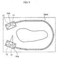
- a guide rail 204A in such a shape that an opened end in a U shape is narrowed down inward may be used, as shown in Fig. 9.
- a measuring head 10A comprising one CCD camera 12 and one slit light source 11, that is, comprising one set of measurement optical systems is used, it is found that the measurable range in the vicinity of the opened end of the guide rail 204A is enlarged.
Landscapes
- Life Sciences & Earth Sciences (AREA)
- Health & Medical Sciences (AREA)
- Biophysics (AREA)
- Physics & Mathematics (AREA)
- Biomedical Technology (AREA)
- Molecular Biology (AREA)
- Pathology (AREA)
- Engineering & Computer Science (AREA)
- Dentistry (AREA)
- Heart & Thoracic Surgery (AREA)
- Medical Informatics (AREA)
- Oral & Maxillofacial Surgery (AREA)
- Surgery (AREA)
- Animal Behavior & Ethology (AREA)
- General Health & Medical Sciences (AREA)
- Public Health (AREA)
- Veterinary Medicine (AREA)
- General Physics & Mathematics (AREA)
- Length Measuring Devices By Optical Means (AREA)
Abstract
In a shape measuring device comprising a measuring head
for measuring the shape of an object to be measured at a
plurality of measuring positions on a guide rail while moving
along the guide rail, the guide rail is in a U shape, and the
measuring head makes measurement for measuring the shape of
the object to be measured which is arranged inside the U-shaped
guide rail at the plurality of measuring positions on
the guide rail while moving along the guide rail.
Description
The present invention relates to a shape measuring
device comprising a measuring head for measuring the shape
of an object to be measured at a plurality of measuring
positions on a guide rail while moving along the guide rail,
and more particularly, to a shape measuring device suited to
measure the shape of a foot.
Conventionally, an active stereo-type shape measuring
device that irradiates a beam of spot tight, slit light, or
the like onto an object to be measured and restores from the
position of a light image observed on a surface of the object
to be measured its three-dimensional shape has been known.
An example of such a shape measuring device is one that scans
spot light or slit light by a rotary mirror in order to measure
the shape of an object to be measured. A magazine "Measurement
and Control" (1999 Vol. 38 No. 4 P285-288) describes a system
for measuring the shape of a foot using such a shape measuring
device.
In the above-mentioned system for measuring the shape
of a foot, one shape measuring device can measure only the
shape of a portion observed from the device and cannot measure
the shape of a portion concealed on the opposite side thereof,
for example. Therefore, 12 shape measuring devices are
arranged around the foot, and the results of the measurement
by the 12 shape measuring devices are synthesized on a
computer, thereby measuring the shape of the whole of the
foot.
In this system, however, the plurality of shape
measuring devices are arranged around the foot. Therefore,
not only the problem that the system increases in size and
increases in cost but also the problem that it is difficult
to synthesize the results of measurement by the plurality of
shape measuring devices with high precision arises.
On the other hand, a shape measuring device that
measures the shape of the whole of an object to be measured
by a measuring person gripping a measuring head and moving
the measuring head around the object to be measured to make
measurement. In the shape measuring device, a plurality of
markers attached to the measuring head are imaged from above
by two cameras, thereby measuring the position and the
direction of the measuring head.
In a case where the shape of a human foot is measured,
it is considered that a guide rail in an elliptical shape (in
such a shape that two sides extending along the lengths of
opposed two semicircles are connected to each other) of such
a size as to enclose the human foot is provided, and a
measuring head is moved along the guide rail.
When the guide rail for moving the measuring head is made
to have a loop shape such as a circular shape or an elliptical.
shape, as described above, the size of an object to be measured
whose shape can be measured is limited by the size of the guide
rail. That is, in a case where the object to be measured is
even slightly larger than a measurable range including the
moving margins of the guide rail and the measuring head, the
shape cannot be measured. Particularly, in a case where the
shape of a foot is measured, the size of the foot differs among
individuals, and differs depending on races. For example,
the feet of the Westerner are larger than those of the
Japanese. Therefore, the foot may not, in some cases, be
arranged inside the guide rail in a loop shape.
The present invention has been made in view of such a
problem and has for its object to provide a shape measuring
device capable of making the size of an object to be measured
which can be measured have a degree of freedom. When a human
foot is measured, for example, an object is to provide a shape
measuring device that can measure the shape of the foot
irrespective of the difference in the size of the foot
depending on adults or children, sex, races, or the like.
In a shape measuring device comprising a measuring head
for measuring the shape of an object to be measured at a
plurality of measuring positions on a guide rail while moving
along the guide rail, a shape measuring device according to
the present invention is characterized in that the guide rail
is in a U shape, and the measuring head makes measurement for
measuring the shape of the object to be measured which is
arranged inside the U-shaped guide rail at the plurality of
measuring positions on the guide rail while moving along the
guide rail.
In a case where the object to be measured is a human foot,
the direction in which the foot is arranged is determined such
that. a direction from inside a curved portion of the U-shaped
guide rail toward an opened portion thereof is a direction
along the length of the foot. In this case, the measuring
head makes measurement for measuring the shape of a foot
arranged inside the U-shaped guide rail at the plurality of
measuring positions on the guide rail while moving along the
guide rail.
In a case where the object to be measured is a human foot,
used as the measuring head is one comprising a light source
for irradiating a light beam toward the foot arranged inside
the U-shaped guide rail and a camera for imaging the light
beam irradiated onto the foot by the light source. The
coordinates of the light beam imaged by the camera are
calculated at the plurality of measuring positions on the
U-shaped guide rail so that the shape of the foot arranged
inside the guide rail is measured.
Description is now made of an embodiment of the present
invention.
Fig. 1 illustrates the schematic configuration of a
shape measuring device according to an embodiment of the
present invention.
A U-shaped guide rail 204 is fixed to a measuring stand
201, and a foot 100 serving as an object to be measured is
put on an area enclosed by the guide rail 204.
Furthermore, a support 202 which is detachable from the
stand 201 is attached to the stand 201, and a horizontal bar
203 is attached to its upper part.
The shape measuring device comprises a measuring head
10 which is moved on the guide rail 204 by a measuring person,
stereo cameras 21 and 22 attached to both ends of the
horizontal bar 203, and a control device 30 composed of a
personal computer for carrying out their control, various
types of operations, and the like. A band-pass filter 23 which
selectively transmits frequency bands of light beams emitted
by six markers 14 shown in Fig. 2 is attached to an imaging
lens of each of the stereo cameras 21 and 22.
Figs. 2 and 3 illustrate the schematic configuration of
the measuring head 10.
The measuring head 10 comprises a casing in a
rectangular parallelepiped shape and opened forward, two CCD
cameras 12a and 12b accommodated in the casing, and a slight
light source 13 so constructed that laser light is scanned
upward and downward to form slit light. Further, the
measuring head 10 comprises a driving mechanism (not shown)
for moving in a clockwise direction or in a counterclockwise
direction along the guide rail 204.
Furthermore, the marker 14 comprising six LED light
sources 14a and 14f is provided on an upper surface of the
casing of the measuring head 10.
The arrangement of the six LED light sources
constituting the marker 14 is not point-symmetrical but
line-symmetrical with respect to the center line of the
measuring head 10 in order to specify the direction of the
measuring head 10. Here, the five LED light sources 14b, 14c,
14d, 14e, and 14f are arranged so as to take a rectangle on
the upper surface of the casing, and the one LED light source
14a is arranged at the position of its center of gravity.
Although at least three LED light sources may be
sufficient as the marker 14 in order to measure the position
and the direction of the measuring head 10 in a three-dimensional
space, four or more LED light sources are used
to improve the measuring precision of the position and the
direction of the measuring head 10 in a least square manner.
The measuring head 10 is attached so as to be movable
along the guide rail 204 by a supporting mechanism (not
shown). Further, the measuring head 10 comprises an encoder
(not shown) for detecting the position of the measuring head
10 using as a basis a predetermined position on the guide rail
204. An output of the encoder 10 is inputted to the control
device 30.
The basic principle of measurement of the shape
measuring device will be described on the basis of Fig. 4.
The coordinates of a certain measuring point A are
measured using the measuring head 10 which is moved on the
guide rail 204 by the measuring person. The measured
coordinates are represented by coordinates (x, y, z) in a
coordinate system using a measuring head as a basis (centered
with respect to a measuring head). The coordinate system is
a coordinate system which moves as the measuring head 10
moves.
On the other hand, the shape of the object to be measured
100 is represented by a fixed coordinate system, and the
coordinate system is referred to as a world coordinate system.
The coordinates, in the world coordinate system, of a
measuring point measured by the measuring head 10 are taken
as (X, Y, Z). The shape of the object to be measured 100 must
be described by the world coordinate system. Accordingly,
the coordinates (x, y, z), in the coordinate system using a
measuring head as a basis, of the measuring point A measured
by the measuring head 10 are converted into the coordinates
(X, Y, Z) in the world coordinate system. The conversion is
performed on the basis of the following equation (1) using
a rotating matrix R and a translation vector t which represent
the movement of the measuring head 10:

Consequently, the coordinates (x, y, z) in the
coordinate system using a measuring head as a basis can be
converted into the coordinates (X, Y, Z) in the world
coordinate system by finding the position and the direction
of the measuring head 10 in the world coordinate system as
the rotating matrix R and the translation vector t.
The measurement of the shape by the shape measuring
device is made by the following procedure for processing.
First, preliminary processing (the following first and
second steps) is performed before making actual measurement.
Specifically, information related to each or measuring
positions of the measuring head 10 in the world coordinate
system is stored in a memory (not shown) carried on the control
device 30 in correspondence with the output value of the
encoder at the measuring position. Information related to
each of the measuring positions of the measuring head 10 in
the world coordinate system is the rotating matrix R and the
translation vector t which represent the movement of the
measuring head 10 in the world coordinate system.
Description is made more concretely.
The coordinates, in the world coordinate system, of each
of the markers 14 provided in the measuring head 10 are
measured by the stereo cameras 21 and 22. Since the position
measuring method has been well known as a stereo method, the
description thereof is omitted.
The coordinates, in the coordinate system using a
measuring head as a basis, of each of the LED light sources
14a to 14f constituting the marker 14 are then respectively
taken as (xi, yi, zi), and the coordinates, in the world
coordinate system, of each of the LED light sources 14a to
14f measured by the stereo cameras 21 and 22 are respectively
taken as (Xi, Yi, Zi), where i is 1, 2, ... 6. The coordinates
(xi, yi, zi) , in the coordinate system using a measuring head
as a basis, of each of the LED light sources 14a to 14f have
already been known.
The rotating matrix R and the translation vector t which
represent the movement of the measuring head 10 are found as
a matrix R and a vector t which satisfy the following equation
(2). The found matrix R and vector t are stored in the memory
in correspondence with the output value of the encoder at the
measuring position of the measuring head 10.

The measuring head 10 is moved along the guide rail 204,
and the above-mentioned processing is repeatedly performed
with respect to all the measuring positions on the guide vail
204, to produce a table representing a correspondence between
the output value of the encoder and the rotating matrix and
the translation vector t at the position.
The support 202 for supporting the stereo cameras 21 and
22 is removed from the stand 201. In such a manner, the object
to be measured 100 is actually measured after the preliminary
processing is completed. Description is now made of a case
where the object to be measured is a human foot 100.
The coordinates of a measuring point on the object to
be measured (foot) 100 in the coordinate system using a
measuring head as a basis are found using the measuring head
10.
Fig. 5 illustrates a method of measuring the position
of a measuring point by the measuring head 10.
As shown in Fig. 5, the coordinate system using a
measuring head as a basis is a coordinate system having the
optical center of the CCD camera 12 as its origin, having the
direction of the optical axis as its z-axis, the horizontal
direction of the CCD camera 12 as its x-axis, and the vertical
direction of the CCD camera 12 as its y-axis. An image surface
S of the CCD camera 12 exists at a position spaced a focal
length f apart from the origin. That is, the image surface
S is a plane parallel to an x-y plane and satisfying z = f.
A method of measuring a position by the measuring head
10 is itself a known measuring method called a light-section
method. A predetermined point on a line irradiated with the
slit light from the slit light source 13 on a surface of the
object to be measured 100 is taken as a measuring point A.
The coordinates, in the coordinate system using a
measuring head as a basis, of the measuring point A are taken
as (x, y, z) , the coordinates of an observing point A'
corresponding to the measuring point A on the image surface
S are taken as (xs, ys, f), and an equation of a plane
representing the slit light is taken as ax + by + cx + d =
0. In the coordinates (xs, ys, f) of the observing point A',
f has already been known as the focal length of the CCD camera
12, and (xs, ys) are found from the pixel position of the slit
light observed on the image surface.
The equation of the plane representing the slit light
is found by the calibration of the measuring head 10.
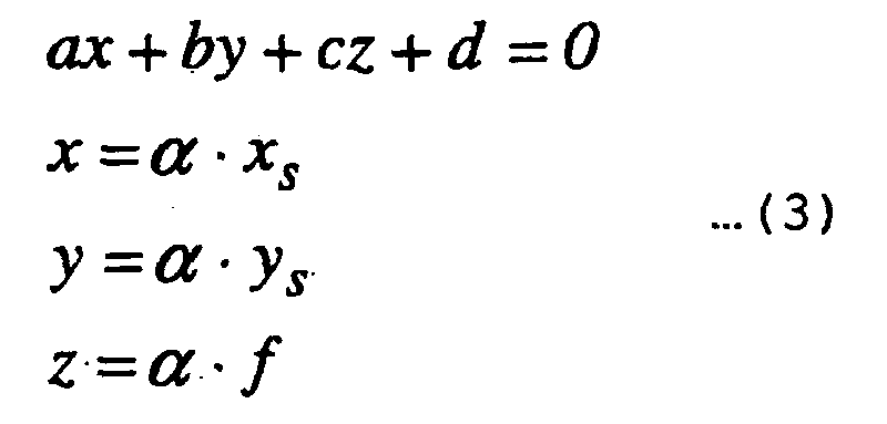
Consequently, a simultaneous equation expressed by the
following equation (3) having x, y, z, and as unknowns is
solved, thereby finding (x, y, z) :
The processing is performed by the control device 30 on
the basis of an output of the CCD camera 12.
In the fourth step, the rotating matrix R and the
translation vector t which correspond to each other are read
out of the memory in the control device 30 on the basis of
the output of the encoder.
In the fifth step, the coordinates (x, y, z), in the
coordinate system using a measuring head as a basis, which
is found in the third step, of the measuring point on the
object to be measured (foot) 100 are converted into the
coordinates (X, Y, Z) in the world coordinate system on the
basis of the rotating matrix R and the translation vector t
which are read out in the fourth step.
The measuring head 10 is moved along the. guide rail 204,
and the processing in the third to fifth steps is repeated
with respect to all the measuring positions on the guide rail
204, thereby finding the shape of the object to be measured
(foot) 100 as a set of the coordinates (X, Y, Z), in the world
coordinate system, of the measuring point obtained each time.
As described in the foregoing, according to the present
embodiment, the coordinates, in the coordinate system using
a measuring head as a basis, of the measuring point obtained
using the measuring head 10 are converted into the coordinates
in the world coordinate system using table data representing
a correspondence between the position on the guide rail 204
of the measuring head 10 and the rotating matrix R and the
translation vector t at the position. Accordingly, the
necessity of the stereo cameras 21 and 22 is eliminated in
making shape measurement, and a user can measure the shape
of the object to be measured without being conscious of the
field of view of a.camera and the tangle of a code, thereby
making it possible to provide higher usability.
Description is made of a method of controlling the
measuring head 10 by the control device 300 in the embodiment
using the U-shaped guide rail 204.
At the time of measurement, the foot is placed inside
the guide rail 204. In this case, the foot is placed with
the central position of a circular arc portion of the. U-shaped
guide rail 204 taken as the center of its heel. To thus place
the foot makes it possible to measure, with respect to feet
of various sizes (various types of feet having different
lengths), the respective shapes of the feet.
Fig. 6 illustrates in a time series manner the movement
of the measuring head 10 in a case where the right foot 100
is placed inside the U-shaped guide rail 204 to measure the
shape of the right foot.
10a indicates a case where the measuring head 10 is at
a left home position LHP. When the measuring head 10 is at
the left home position LHP, the measuring head 10 is moved
in a counterclockwise direction along the guide rail 204 from
the left home position LHP.
10b indicates a case where the measuring head 10 is at
the position where the toe of the right foot 100 is detected.
10c indicates a case where the measuring head 10 is at a camera
switching position for a right foot SWP1 set near the right
ankle of the right foot 100. 10d indicates a case where the
measuring head 10 is at the position where the measurement
is terminated, which is calculated from the position where
the toe is detected, indicated by 10a. 10e indicates a case
where the measuring head 10 is at a right home position RHP.
Fig. 7 shows the procedure for control processing of the
measuring head 10 by the control device 300.
First, processing in the steps S1 to S4 is performed as
measurement preparation processing.
In the measurement preparation processing, the
direction of measurement is first acquired (step S1). That
is, the direction of movement of the measuring head 10 (a
clockwise direction or a counterclockwise direction) is
acquired. When the foot has already been measured, the
direction of subsequent measurement is stored in the final
step S15, described later, so that the stored direction of
subsequent measurement is acquired as the current direction
of measurement. When the direction of subsequent measurement
is not stored, the direction of measurement in which the
movement is started is automatically selected on the basis
of a home position near the current position of the measuring
head 10.
That is, the counterclockwise direction is selected as
the direction of measurement when the measuring head 10 is
at a position near the left home position LHP, while the
clockwise direction is selected as the direction of
measurement when the measuring head 10 is at a position near
the right home position RHP. In this example, it is assumed
that the measuring head 10 is at the position near the left
home position LHP, and the counterclockwise direction is
acquired as the direction of measurement.
The results of selection as to whether the foot to be
measured is a right foot or a left foot is then acquired (step
S2). Selection as to whether the foot to be measured is a
right foot or a left foot is made by an operator performing
a predetermined selection operation on a display with respect
to the control device 300. In this example, it is assumed
that the right foot is selected, as in the example shown in
Fig. 6.
The measuring head 10 is then moved to the home position
(HP) determined by the direction of measurement (step S3).
That is, the measuring head 10 is moved to the left home
position LHP (the position indicated by 10a in Fig. 6) when
the direction of measurement is the counterclockwise
direction, while being moved to the right home position RHP
(the position indicated by 10e in Fig. 6) when the direction
of measurement is the clockwise direction. In this example,
it is assumed that the measuring head 10 is moved to the left
home position LHP because the direction of measurement is the
counterclockwise direction.
Thereafter, the camera first used for the measurement
is selected on the basis of the direction of measurement (step
S4). That is, out of the two cameras 12a and 12b, the camera
positioned on the rear side in the direction of measurement
is selected. The camera 12a is selected when the direction
of movement is the counterclockwise direction, while the
camera 12b is selected when the direction of measurement is
the clockwise direction.
In this example, it is assumed that the camera 12a is
selected as the camera first used for measurement.
Consequently, the camera which more easily detects the toe,
that is, the camera 12a positioned on the rear side in the
direction of movement is selected as the camera first used
for measurement, as indicated by 10b in Fig. 6.
When the measurement preparation processing in the
Steps S1 to S4 is terminated, toe search processing in the
steps S5 to S7 is performed. The toe search processing is
processing for detecting the toe of the foot. In the toe
search processing, shape measurement is not made.
In the toe search processing, measurement for detecting
the toe (the tip of the foot) is first started by increasing
the movement speed of the measuring head 10 (step S5). That
is, measurement for detecting the toe is made while moving
the measuring head 10 at high speed, as indicated by an arrow
V1 in Fig. 8. When the toe is detected (step S6), the measuring
head 10 is stopped, to store in the memory the position of
the detected toe (the position of the tip of the foot) as well
as to calculate the position where the measurement is
terminated from the position of the detected toe and store
the calculated position in the memory (step S7).
In this example, the measuring head leads to the
position indicated by 10b in Fig. 6, so that the position of
the toe is detected. From the position of the detected toe,
the position of a right-hand portion of the guide rail 204
(the position indicated by 10d in Fig. 6) corresponding
thereto is calculated as the position where the measurement
is terminated.
In the toe search processing, the measuring head 10 is
moved at high speed, so that the measuring head 10 goes beyond
(overruns) the position corresponding to the position of the
tip of the foot at the time point where the tip of the foot
is found. Therefore, the measuring head 10 is returned by
a predetermined distance (approximately 3 to 5 cm) at high
speed (step S8). In this example, the measuring head 10 is
moved by a predetermined distance in a clockwise direction,
as indicated by an arrow V2 in Fig. 8.
Actual measurement processing in the steps S9 to S12
will be then performed. In this measurement processing,
measurement processing for measuring the shape of the foot
is performed. In this measurement processing, measurement
processing in a precise mode is first performed (step S9).
That is, measurement processing is performed while moving the
measuring head 10 at low speed and with the spacing between
the measuring positions reduced. In this example, the
measurement processing is performed while moving the
measuring head 10 at low speed and with the spacing between
the measuring positions reduced, as indicated by an arrow V3
in Fig. 8.
The reason why the measurement processing in a precise
mode is thus performed in the vicinity of an opened end of
the guide rail 204 is that the measurement precision is made
lower because the measurement is made by the camera arranged
beside the toe of the foot in the vicinity of the opened end
of the guide rail 204, as compared with that at a curved
portion of the guide rail 204, so that the spacing between
the measuring positions is reduced to heighten the
measurement precision.
When the measuring head 10 goes beyond a range set to
approximately 5 cm, for example, from the position of the toe,
measurement processing in a normal mode is performed (step
S10). That is, after the measuring head 10 passes through
the vicinity of the toe, measurement processing is performed
while moving the measuring head 10 at intermediate speed and
with the spacing between the measuring positions increased.
In this example, the measurement processing is performed
while moving the measuring head 10 at intermediate speed and
with the spacing between the measuring positions increased,
as indicated by an arrow V4 in Fig. 8.
The spacing between the measuring positions in the
measurement processing in a normal mode is set to
approximately 1.5 times the spacing between the measuring
positions in the measurement processing in a precise mode.
The range in which the measurement processing in a precise
mode in the step S9 is performed can be previously set in the
control device 30 or automatically set on the basis of the
size of the foot.
When the measuring head 10 reaches a predetermined
camera switching position while the measurement processing
in a normal mode in the step S10 is being performed, the camera
used for the measurement is switched (step S11). In a case
where the right foot is measured, when the measuring head 10
reaches the camera switching position for a right foot SWP1
(see Fig. 6) set in the vicinity of the right ankle
irrespective of the direction of measurement, the camera used
for the measurement is switched. In a case where the left
foot is measured, when the measuring head 10 reaches the
camera switching position for a left foot SWP2 (see Fig. 6)
set in the vicinity of the left ankle irrespective of the
direction of measurement, the camera used for the measurement
is switched.
In this example, the right foot is measured, and the
camera first used for the measurement is the camera 12a. When
the measuring head 10 reaches the camera switching position
for a right foot SWP1 shown in Fig. 6, therefore, the camera
used for the measurement is switched from the first camera
12a to the second camera 12b.
Even after the camera used for the measurement is
switched, the measurement processing in a normal mode is
performed (step S12).
When the camera used for the measurement is switched,
the position of the camera used for the measurement is
changed, so that operation processing for shape measurement
is also switched. The camera used for the measurement is
switched, so that the effect of a measuring error is small
because there are relatively few irregularities at the
position of the ankle of the foot even if there occurs such
inconvenience that an error or discontinuity slightly occurs
in the operation processing for shape measurement.
Thereafter, when the measuring head 10 reaches a
position 5 cm ahead of the toe, measurement processing in a
precise mode is performed (step S13). In this example, the
measurement processing is performed while moving the
measuring head 10 at low speed and with the spacing between
the measuring positions reduced, as indicated by an arrow V5
in Fig. 8.
It is judged whether or not the measuring head 10 reaches
the position 5 cm ahead of the toe by taking the position where
the measurement is terminated (the position indicated by 10d
in Fig. 6 in this example), which is calculated in the step
S7, as the position of the toe. The measurement processing
in the step S13 is continued until the measuring head 10
reaches the position where the measurement is terminated (the
position indicated by 10d in Fig. 6 in this example) or a
position a predetermined distance (e.g., approximately 2cm)
beyond the position.
As described in the foregoing, when the measurement
processing for measuring the shape of the right foot is
terminated, the measuring head is moved at high speed to the
home position determined by the direction of measurement
(step S14). When the direction of measurement is the
counterclockwise direction as in this example, the measuring
head 10 is moved to the right home position RHP, as indicated
by an arrow V6 in Fig. 8. When the direction of measurement
is the clockwise direction, the measuring head 10 is moved
to the left home position LHP.
Thereafter, a direction opposite to the direction of
current measurement is stored in the memory as the direction
of subsequent measurement (step S15). The current processing
for controlling the measuring head 10 is terminated.
According to the above-mentioned embodiment, the guide
rail is in a U shape. Accordingly, the size of the object
to be measured and particularly, the length of the object to
be measured can be made to have a degree of freedom, as
compared with a shape measuring device having a guide rail
in a loop shape such as a circular shape or an elliptical
shape.
Although in the above-mentioned embodiment, the foot is
arranged such that the toe of the foot is directed toward the
opened end of the U-shaped guide rail 204 and the heel of the
foot is positioned on the side of the curved portion of the
guide rail 204, the foot may be arranged such that the heel
is directed toward the opened end of the U-shaped guide rail
204 and the toe is positioned on the side of the curved portion
of the guide rail 204. This makes it possible to increase
the measuring precision of the toe.
Although in the above-mentioned embodiment,
information related to the position of the measuring head in
the world coordinate system, that is, the rotating matrix R
and the translation vector t are found using the outputs of
the stereo cameras 21 and 22 , the rotating matrix R and the
translation vector t can be found without using the stereo
cameras 21 and 22 if the track of the guide rail 204 with
respect to the stand 201 is previously specified.
Although description was made of the embodiment using
the U-shaped guide rail 204, an embodiment utilizing an
elliptical guide rail 204 which is sufficiently long in the
longitudinal direction is within the range of the right of
the present invention in a case where the measuring head 10
is moved in one of circular arc portions of the guide rail
204 so as to measure the heel, while not being moved in the
other circular arc portion, that is, a case where the guide
rail 204 is used as a substantially U-shaped guide rail.
For example, when the shape of the foot of an adult is
measured, the whole of the elliptical guide rail may be
utilized, to make shape measurement of such a system that a
measuring head goes around the whole of the guide rail. On
the other hand, when the shape of the foot of a child is
measured, a part of the elliptical guide rail may be utilized
as the U-shaped guide rail in the above-mentioned embodiment
by arranging the foot in such a manner that the heel of the
foot is positioned at the central position of one of circular
arcs of the guide rail.
Furthermore, used as the measuring head 10 may be one
different from that in the above-mentioned embodiment,
provided that it measures the position of a measuring point
on an object to be measured by an active stereo measuring
method. For example, the slit light source 13 may be replaced
with a spot light source. Although used as the above-mentioned
measuring head 10 is one comprising two sets of
measurement optical systems, that is, two CCD cameras 12a and
12b and one slit light source 13, a measuring head comprising
one set of measurement optical systems, that is , a measuring
head comprising a CCD camera and one slit light source may
be used.
Although used as the U-shaped guide rail is one
comprising a semicircular curved portion and two straight
line portions respectively extending from both ends thereof,
a guide rail which differs in shape from that shown in Fig.
6 may be used, provided that it is in an approximately U shape.
In order to enlarge the measurable range of the opened
end, for example, a guide rail 204A in such a shape that an
opened end in a U shape is narrowed down inward may be used,
as shown in Fig. 9. As shown in Fig. 9 , even in a case where
a measuring head 10A comprising one CCD camera 12 and one slit
light source 11, that is, comprising one set of measurement
optical systems is used, it is found that the measurable range
in the vicinity of the opened end of the guide rail 204A is
enlarged.
Claims (4)
- In a shape measuring device comprising a measuring head for measuring the shape of an object to be measured at a plurality of measuring positions on a guide rail while moving along the guide rail,
a shape measuring device characterized in that the guide rail is in a U shape, and the measuring head makes measurement for measuring the shape of the object to be measured which is arranged inside the U-shaped guide rail at the plurality of measuring positions on the guide rail while moving along the guide rail. - The shape measuring device according to claim 1, characterized in that the object to be measured is a human foot, and the direction in which the foot is arranged is determined such that a direction from inside a curved portion of the U-shaped guide rail toward an opened portion thereof is a direction along the length of the foot.
- The shape measuring device according to claim 2, characterized in that the measuring head makes measurement for measuring the shape of a foot arranged inside the U-shaped guide rail at the plurality of measuring positions on the guide rail while moving along the guide rail.
- The shape measuring device according to claim 3, characterized in that the measuring head comprises a light source for irradiating a light beam toward the foot arranged inside the U-shaped guide rail and a camera for imaging the light beam irradiated onto the foot by the light source, the coordinates of the light beam imaged by the camera being calculated at the plurality of measuring positions on the U-shaped guide rail so that the shape of the foot arranged inside the guide rail is measured.
Applications Claiming Priority (3)
| Application Number | Priority Date | Filing Date | Title |
|---|---|---|---|
| JP2001217309 | 2001-07-17 | ||
| JP2001217309 | 2001-07-17 | ||
| PCT/JP2002/007186 WO2003008904A1 (en) | 2001-07-17 | 2002-07-15 | Shape measuring device |
Publications (1)
| Publication Number | Publication Date |
|---|---|
| EP1418398A1 true EP1418398A1 (en) | 2004-05-12 |
Family
ID=19051657
Family Applications (1)
| Application Number | Title | Priority Date | Filing Date |
|---|---|---|---|
| EP02746070A Withdrawn EP1418398A1 (en) | 2001-07-17 | 2002-07-15 | Shape measuring device |
Country Status (5)
| Country | Link |
|---|---|
| US (1) | US20040184040A1 (en) |
| EP (1) | EP1418398A1 (en) |
| JP (1) | JPWO2003008904A1 (en) |
| CN (1) | CN1533495A (en) |
| WO (1) | WO2003008904A1 (en) |
Cited By (5)
| Publication number | Priority date | Publication date | Assignee | Title |
|---|---|---|---|---|
| WO2006045285A1 (en) * | 2004-10-29 | 2006-05-04 | Wincor Nixdorf International Gmbh | Device for the three-dimensional measurement of objects |
| WO2009050238A1 (en) * | 2007-10-19 | 2009-04-23 | Ctc | Method and device for the three-dimensional reconstruction of the inner surface of a shoe |
| FR2982664A1 (en) * | 2011-11-10 | 2013-05-17 | Spincontrol | Contactless telemetry table for measurement of position of e.g. subject in medical diagnosis field, has software package allowing sending of data acquisition controls and selection of exploitable data and suppression of aberration |
| WO2018054398A1 (en) * | 2016-09-20 | 2018-03-29 | Tomas Bata University In Zlin | A device for the 3d scanning of spatial objects, in particular of the sole and adjacent parts of the human foot |
| WO2018065803A1 (en) | 2016-10-05 | 2018-04-12 | Last Foot Technology B.V. | Foot shape acquisition using depth sensor and pressure plate technology |
Families Citing this family (9)
| Publication number | Priority date | Publication date | Assignee | Title |
|---|---|---|---|---|
| SI22424A (en) | 2006-11-07 | 2008-06-30 | ALPINA, tovarna obutve, d.d., Žiri | Device and procedure for threedimensional measurement of body shape |
| CN102301201B (en) * | 2009-02-18 | 2013-02-27 | 旭硝子株式会社 | Method for measuring the shape of a rectangular plate and a method for correcting the relative position of an imaging unit |
| CN106377015B (en) * | 2015-04-15 | 2020-04-21 | 郑士超 | a foot scanner |
| CN106307812A (en) * | 2016-07-29 | 2017-01-11 | 成都卡美多鞋业有限公司 | Shoe dimension processing precision measuring system |
| KR101932457B1 (en) * | 2018-03-06 | 2018-12-26 | 이홍규 | Apparatus for generating information regarding inside of shoes, and method using the same |
| KR101972805B1 (en) * | 2018-03-08 | 2019-04-30 | 스코프비전 유한책임회사 | Inspection Method for Shoes Sole |
| FR3081687B1 (en) * | 2018-06-01 | 2021-03-12 | Lyamtech | CUSTOM SHOE COMPONENT MANUFACTURING PROCESS |
| CN111407042A (en) * | 2020-03-12 | 2020-07-14 | 正峰激光自动化(深圳)有限公司 | Shoe shape edge-searching machine |
| CN116929248B (en) * | 2023-07-27 | 2024-03-22 | 浙江卓诗尼鞋业有限公司 | Full-automatic detection table and detection system for shoe body |
Family Cites Families (5)
| Publication number | Priority date | Publication date | Assignee | Title |
|---|---|---|---|---|
| US5198877A (en) * | 1990-10-15 | 1993-03-30 | Pixsys, Inc. | Method and apparatus for three-dimensional non-contact shape sensing |
| JPH06249626A (en) * | 1993-02-26 | 1994-09-09 | Kenji Mimura | Three-dimensional shape measuring device |
| JPH0914930A (en) * | 1995-06-30 | 1997-01-17 | Matsushita Electric Ind Co Ltd | Shape measuring method and its measuring device |
| WO2000073738A1 (en) * | 1999-05-26 | 2000-12-07 | Sanyo Electric Co., Ltd. | Shape measuring device |
| JP3370049B2 (en) * | 1999-05-26 | 2003-01-27 | 三洋電機株式会社 | Shape measuring device |
-
2002
- 2002-07-15 EP EP02746070A patent/EP1418398A1/en not_active Withdrawn
- 2002-07-15 JP JP2003514203A patent/JPWO2003008904A1/en active Pending
- 2002-07-15 WO PCT/JP2002/007186 patent/WO2003008904A1/en not_active Ceased
- 2002-07-15 CN CNA028144228A patent/CN1533495A/en active Pending
- 2002-07-15 US US10/483,832 patent/US20040184040A1/en not_active Abandoned
Non-Patent Citations (1)
| Title |
|---|
| See references of WO03008904A1 * |
Cited By (7)
| Publication number | Priority date | Publication date | Assignee | Title |
|---|---|---|---|---|
| WO2006045285A1 (en) * | 2004-10-29 | 2006-05-04 | Wincor Nixdorf International Gmbh | Device for the three-dimensional measurement of objects |
| WO2009050238A1 (en) * | 2007-10-19 | 2009-04-23 | Ctc | Method and device for the three-dimensional reconstruction of the inner surface of a shoe |
| FR2922640A1 (en) * | 2007-10-19 | 2009-04-24 | Ct Tech Cuir Chaussure Maroqui | METHOD AND DEVICE FOR THREE-DIMENSIONAL RECONSTRUCTION OF THE INTERNAL SURFACE OF A SHOE |
| FR2982664A1 (en) * | 2011-11-10 | 2013-05-17 | Spincontrol | Contactless telemetry table for measurement of position of e.g. subject in medical diagnosis field, has software package allowing sending of data acquisition controls and selection of exploitable data and suppression of aberration |
| WO2018054398A1 (en) * | 2016-09-20 | 2018-03-29 | Tomas Bata University In Zlin | A device for the 3d scanning of spatial objects, in particular of the sole and adjacent parts of the human foot |
| WO2018065803A1 (en) | 2016-10-05 | 2018-04-12 | Last Foot Technology B.V. | Foot shape acquisition using depth sensor and pressure plate technology |
| EP4063782A1 (en) | 2016-10-05 | 2022-09-28 | SafeSize Holding B.V. | Foot shape acquisition using depth sensor and pressure plate technology |
Also Published As
| Publication number | Publication date |
|---|---|
| WO2003008904A1 (en) | 2003-01-30 |
| CN1533495A (en) | 2004-09-29 |
| US20040184040A1 (en) | 2004-09-23 |
| JPWO2003008904A1 (en) | 2004-11-11 |
Similar Documents
| Publication | Publication Date | Title |
|---|---|---|
| US10136970B2 (en) | System, device, and method for dental intraoral scanning | |
| US20040184040A1 (en) | Shape measuring device | |
| JP4888127B2 (en) | Three-dimensional measuring device and portable measuring instrument | |
| US7800643B2 (en) | Image obtaining apparatus | |
| US20150054946A1 (en) | Real-time inspection guidance of triangulation scanner | |
| US20150097931A1 (en) | Calibration of 3d scanning device | |
| CN108225190B (en) | Measuring system | |
| US20120281240A1 (en) | Error Compensation in Three-Dimensional Mapping | |
| EP1197729A1 (en) | Shape measuring device | |
| JP4402458B2 (en) | Method for determining corresponding points in 3D measurement | |
| US20150097968A1 (en) | Integrated calibration cradle | |
| WO2020246047A1 (en) | Lens shape measurement device, lens shape measurement method, lens optical property measurement device, program, and recording medium | |
| JP2024175057A (en) | Medical 3D image measuring device and medical image matching system | |
| JP6702343B2 (en) | Shape measuring device, structure manufacturing system, and shape measuring method | |
| JP2001241928A (en) | Shape measuring device | |
| JP2004077262A (en) | Three-dimensional imaging apparatus and method | |
| JP3408237B2 (en) | Shape measuring device | |
| JP6653048B1 (en) | Lens shape measuring device, lens shape measuring method, lens optical characteristic measuring device, program, and recording medium | |
| JP6287153B2 (en) | Sensor unit, shape measuring device, and structure manufacturing system | |
| JP2003090711A (en) | Three-dimensional image pickup apparatus and method | |
| JP3370049B2 (en) | Shape measuring device | |
| JP2004193947A (en) | Three-dimensional imaging apparatus and method | |
| JP2523420B2 (en) | Image processing method in optical measuring device | |
| JP2001241927A (en) | Shape measuring device | |
| JP4167453B2 (en) | Digitizer and coordinate recognition sheet |
Legal Events
| Date | Code | Title | Description |
|---|---|---|---|
| PUAI | Public reference made under article 153(3) epc to a published international application that has entered the european phase |
Free format text: ORIGINAL CODE: 0009012 |
|
| 17P | Request for examination filed |
Effective date: 20040216 |
|
| AK | Designated contracting states |
Kind code of ref document: A1 Designated state(s): AT BE BG CH CY CZ DE DK EE ES FI FR GB GR IE IT LI LU MC NL PT SE SK TR |
|
| STAA | Information on the status of an ep patent application or granted ep patent |
Free format text: STATUS: THE APPLICATION HAS BEEN WITHDRAWN |
|
| 18W | Application withdrawn |
Effective date: 20060726 |