Technical Field
-
The present invention relates to a connecting
configuration for connecting the tip of the member to a
mounting hole, i.e., a column is connected to a wooden board
such as a top board or a bottom board, which is employed for
a sectional casing for storing and organizing clothes or
small articles, for example.
Background Art
-
As an example of a sectional casing employing wooden
boards, a sectional casing formed of plastic has been
proposed by the present applicant, which is disclosed in
Japanese Registered Utility Model No. 3057166. All the
components including a top board of the aforementioned
sectional casing are formed of plastic, and accordingly, the
sectional casing has the advantage of low costs and the like,
as well as having the advantage of light weight for easy
carrying, and thus, there is a widespread demand for such
sectional casing in the market. On the other hand, in
recent years, in many cases, a wooden top board is employed
in such sectional casing to meet the preference of the user
for natural materials. In general, the tip of a column
formed of plastic is inserted to a mounting hole formed on
the rear face of a wooden board, and is fixed with inserting
screws or the like, so as to connect the column formed of
plastic to the wooden board.
-
However, a preformed wooden board has the disadvantage
of poor precision as compared with a preformed plastic board
or the like, often leading to a problem of looseness between
the mounting hole formed thereon and the tip of the column
inserted thereto.
-
The present invention has been made in order to solve
the above-described problem, and accordingly, it is an
object thereof to provide a connecting configuration for
connecting a column to a mounting hole formed on a wooden
board, without being influenced by margin of error in the.
size of the mounting hole formed of the wooden board.
Disclosure of Invention
-
With a connecting configuration for connecting a member
tip portion to a mounting hole according to the present
invention, a connecting member is introduced between the
member tip portion and the mounting hole, and the connecting
member comprises a member body formed so as to be fit to the
member tip portion, and support portions provided to the
member body, for supporting the member body pushed into the
mounting hole.
-
Furthermore, the aforementioned mounting hole includes
flange portions on the entrance side thereof for securely
supporting the member tip portion or the connecting member.
-
Furthermore, the connecting member may include flexible
tips which bend outward at the time of insertion of the
aforementioned member tip portion.
Brief Description of the Drawings
-
- Fig. 1 is a disassembled perspective view of a
sectional casing according to a first embodiment.
- Fig. 2 is a perspective view of a connecting member.
- Fig. 3 a partially enlarged cross-sectional view of the
sectional casing, taken along line X-X shown in Fig. 1.
- Fig. 4 is a perspective view which illustrates a first
modification.
- Fig. 5 is a perspective view which illustrates a second
modification.
- Fig. 6 is a perspective view which illustrates a third
modification.
- Fig. 7 is a front view which illustrates a mounting
hole and an end mill according to a second embodiment.
- Fig. 8 is a perspective view which illustrates the
mounting hole and the end mill according to the second
embodiment.
- Fig. 9 is a cross-sectional view taken along line A-A
in Fig. 8.
- Fig. 10 is a side view which illustrates a connecting
member according to the second embodiment.
- Fig. 11 is a partial front view which illustrates the
connecting member according to the second embodiment.
- Fig. 12 is a perspective view which illustrates a
mounting hole according to a first modification of the
second embodiment.
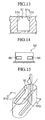
- Fig. 13 is a cross-sectional view taken along line B-B
in Fig. 12.
- Fig. 14 is a side view which illustrates a connecting
member according to the first modification of the second
embodiment.
- Fig. 15 is a perspective view which illustrates a
mounting hole according to a second modification of the
second embodiment.
- Fig. 16 is a cross-sectional view taken along line C-C
in Fig. 15.
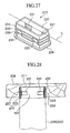
- Fig. 17 is a side view which illustrates a connecting
member according to the second modification of the second
embodiment.
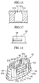
- Fig. 18 is a perspective view which illustrates a
connecting member according to a third embodiment.
- Fig. 19 is a perspective view which illustrates the
inner face of the connecting member according to the third
embodiment.
- Fig. 20 is a cross-sectional view which shows the state
wherein the connecting member according to the third
embodiment is mounted to the mounting hole.
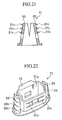
- Fig. 21 is a cross-sectional view which illustrates a
connecting member according to a modification of the third
embodiment.
- Fig. 22 is a perspective view which illustrates a
connecting member according to a fourth embodiment.
- Fig. 23 is a cross-sectional view which shows a state
of the connecting member according to the fourth embodiment
being partway mounted to the mounting hole.
- Fig. 24 is a cross-sectional view which shows a state
wherein the connecting member according to the fourth
embodiment is mounted to the mounting hole.
- Fig. 25 is a disassembled perspective view of a
sectional casing according to a fifth embodiment.
- Fig. 26 is an enlarged view of principal components of
the sectional casing shown in Fig. 25.
- Fig. 27 is a perspective view of a connecting member.
- Fig. 28 is a cross-sectional view of the sectional
casing, taken along line B-B shown in Fig. 26.
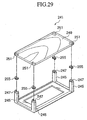
- Fig. 29 is a disassembled perspective view of a
sectional casing according to a modification of the fifth
embodiment.
- Fig. 30 is an enlarged view of principal components of
the sectional casing shown in Fig. 29.
- Fig. 31 is a perspective view of the connecting member
shown in Fig. 29.
-
Best Mode for Carrying Out the Invention
-
Description will be made below regarding a first
embodiment according to the present invention with reference
to the drawings.
-
Note that a sectional casing described in the present
embodiment is an example of application to a connecting
configuration for connecting a column to a wooden board.
The present invention is not restricted to any particular
arrangement, and may be applied to others, e.g., a table
wherein a wooden top board is supported with columns, or the
like. Furthermore, the wooden board may be used as a bottom
board, for example. In a case of the top board, the column
is connected to the rear face of the top board. On the
other hand, in a case of the bottom board, the column is
connected to the front face of the bottom board.
(Basic configuration of sectional casing)
-
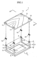
As shown in Fig. 1, a sectional casing 1 comprises a
casing main unit 2 formed of plastic, a wooden top board 9
mounted on the upper side of the casing main unit 2, and a
tray 17 formed of plastic, which is stored in the casing
main unit 2. The casing main unit 2 includes a rectangular
frame 3 forming the bottom thereof, and four columns 5,
5, .., erected from each corner of the rectangular frame 3.
The casing main unit 2 has a configuration wherein the tray
17 denoted by imaginary lines can be detachably mounted in
the direction of the arrow A shown in Fig. 1. While each
column 5 is integrally formed with the rectangular frame 3,
an arrangement may be made wherein separately formed columns
5 and rectangular frame 3 are assembled. Furthermore, an
arrangement may be made wherein a wooden board is employed
instead of the rectangular frame 3. Furthermore, an
arrangement may be made wherein side boards (not shown) are
mounted on the sides of the casing main unit 2, as viewed
from the direction of the tray 17 being detachably mounted.
Note that while the casing main unit 2 of the sectional
casing 1 shown in Fig. 1 has a configuration including a
single casing main unit 2, the sectional casing 1 may have a
configuration wherein multiple casing main units 2 are
stacked.
-
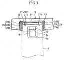
As shown in Fig. 2 and Fig. 3, column tip portions 7,
each serving as a tip of a column 5, include a U-shaped
groove 7a so as to form an elastic bending tip 8.
Furthermore, the elastic bending tip 8 includes an engaging
protrusion 8a on the base thereof. The elastic bending tip
8 has a configuration wherein external force applied to the
elastic bending tip 8 causes change in the shape thereof,
thereby pushing an engaging protrusion 8a into the column
tip portion 7.
(Configuration of wooden top board)
-
As shown in Fig. 1, the wooden top board 9 is formed in
a rectangular shape with a somewhat larger size than the
casing main unit 2. The portions of the wooden top board 9,
each of which match positions of the columns 5 of the casing
main unit 2, include four mounting holes 11, 11, 11, 11,
drilled by an end mill or the like. As a result of
formation of these holes, each mounting hole 11 includes an
inner side face 13 on the side of the inner face thereof
(see Fig. 3). The mounting holes 11 are formed with a
slightly smaller inner size than the outer size of
connecting members 15 so that the connecting members 15 can
be pushed thereinto. The wooden top board 9 may be formed
of a single board formed of wood, or may be formed of
plywood, a particle board formed of wooden particles, or the
like. Furthermore, printing a wood grain pattern on the
surface of the top wooden board 9, or applying paper with a
wood grain pattern print thereupon, is advantageous with
regard to appearance.
(Configuration of connecting member)
-
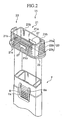
Description will be made regarding the connecting
member 15 with reference to Fig. 2 and Fig. 3. The
connecting member 15 is formed of plastic. The connecting
member 15 generally comprises a member body 21, a pair of
support portions 23 and 23 disposed on both sides of the
member body 21, a mounting flange 25 disposed at the lower
portion of the member body 21. The member body 21 includes
a perimeter wall 21a for surrounding the column tip portion
7 fit thereto, multiple (or a single) slits 21b, ...,
extending downward from the upper end of the perimeter wall
21a, multiple slip-preventing protrusions 21c formed on the
outer face of the perimeter wall 21a. The slits 21b, ...,
improve flexibility for enabling the perimeter wall 21a to
be deformed, or enabling the shape thereof to be changed, at
the time of the connecting member 15 being pushed into the
mounting hole 11. The mounting flange 25 is included for
coming into contact with the rear face of the wooden top
board 9 so as to prevent looseness of the connecting member
15 at the time of the connecting member 15 being pushed into
the mounting hole 11 of the wooden top board 9 as shown in
Fig. 3. The perimeter wall 21a includes engaging openings
27 and 27. The engaging opening 27 engages with the
engaging protrusion 8a of the column top portion 7 so as to
prevent the column tip portion 7 from slipping from the
connecting member 15 (perimeter wall 21a).
-
The support portions 23 comprise connecting arms 23a
and 23a, extending from the perimeter wall 21a in the side
direction thereof, and support wall portions 23b and 23b
disposed at the tips the connecting arms 23a and 23a.
Furthermore, the base portions of the connecting arms 23a
and 23a, and the support wall portions 23b and 23b, are
connected to the upper face of the mounting flange 25 for
improving strength. Furthermore, each support wall portion
23b is tapered slightly upward from the base portion so as
to facilitate pushing the connecting member 15 into the
mounting hole 11, and each support wall portion 23b includes
slip-preventing protrusions 23c, ..., (see Fig. 2). The
connecting arms 23a and the support wall portions 23b have
elasticity for enabling these members to be deformed in a
predetermined range. The slip-preventing protrusions 23c ...,
included in the support portions 23 reduce the influence of
the margin of error in the size of the mounting holes 11 ...,
formed on the wooden board 9, thereby reducing adverse
effects due to the margin of error therein.
-
As shown in Fig. 2 and Fig. 3, each of the slip-preventing
protrusions 21c and 23c are formed with a
triangular cross-sectional shape so as to have a tapered
face on the side of the perimeter wall face 13. These slit-preventing
protrusions have a configuration for facilitating
pushing the connecting member 15 into the mounting hole 11,
as well as the connecting member 15 engaging with the
perimeter wall face 13 of the mounting hole 11 so as to
prevent the connecting member 15 from slipping from the
mounting hole 11 following the connecting member 15 being
pushed into the mounting hole 11. Furthermore, this
configuration has the advantage of reducing influence due to
irregularities in the inner diameter of the mounting hole 11
due to change in degree of engaging between each of the
slip-preventing protrusions 21c and 23c, and the perimeter
wall face 13, even in the event that the mounting hole 11 is
formed with irregularities in the inner diameter.
(Assembling of sectional casing)
-
Description will be made regarding the assembling
procedure for the sectional casing 1 with reference to Fig.
1 through Fig. 3. First, each connecting member 15 is
pushed into the corresponding mounting hole 11 of the wooden
top board 9. The connecting member 15 is formed in a
horizontally symmetric manner, and accordingly, there is no
need to select a particular inserting direction. With the
connecting member 15 pushed into the mounting hole 11, the
slip-preventing protrusions 21c and 23c engage with the
perimeter wall face 13 (curved portion 13a) of the mounting
hole 11 so as to prevent the connecting member 15 from
slipping from the mounting hole 11. In the event that the
size of the mounting hole 11 is too small due to
irregularities in the size thereof, deformation of the
perimeter wall 21a or the support portions 23 of the
connecting member occurs, and on the other hand, in the
event that the size thereof is too large, change in engaging
by the slip-preventing protrusions 21c and 23c occurs,
thereby reducing the influence due to the margin of error in
the size thereof. The slits 21b, ..., enable the perimeter
wall 21a to be deformed for the connecting member 15 being
elastically supported by the mounting hole 11. Next, the
column tip portion 7 of each column 5 is fit to the member
body 21 of the corresponding connecting member 15.
-
At the time of the column tip portion 7 being fit to
the member body 21, the engaging protrusion 8a is pressed
into contact with the end face of the perimeter wall 21a,
whereby the engaging protrusion 8a is retracted, as well as
the elastic bending tip 8 being bent and retracted. The
retracted engaging protrusion 8a engages with the engaging
opening 27 of the perimeter wall 21a, whereby the elastic
bending tip 8 is returned to the normal position due to the
elasticity thereof. As described above, each engaging
protrusion 8a engages with the corresponding engaging
opening 27, whereby connection of the columns 5 to the
wooden top board 9 through the connecting member 15 is
completed. Last, the tray 17 is stored between the columns
5, whereby assembling of the sectional casing 1 is completed.
(Advantages of the first embodiment)
-
With the connecting configuration according to the
present invention, the columns can be connected to the
wooden board without being influenced by the adverse effects
due to the margin of error in the size of the mounting holes
on the wooden board. Thus, the connecting configuration
according to the present invention enables working of wooden
boards, which tend to have poor dimensional precision, to be
easily performed.
-
Furthermore, each column 5 is easily and securely
connected to the corresponding mounting hole 11 on the
wooden top board 9 with the connecting member 15.
(Modifications of the first embodiment)
-
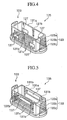
Description will be made regarding modifications of the
present embodiment with reference to Fig. 4 through Fig. 6.
First, the difference between a first modification shown in
Fig. 4 and the present embodiment is the configuration of
the engaging openings 27 and the slits 21b. While the
configuration according to the present embodiment includes
the single engaging opening 27 and the four slits 21b, the
configuration according to the first modifications includes
the four engaging openings and the two slits. That is to
say, a connecting member 125 includes four engaging openings
127, ..., and two slits 121b and 121b, formed on a perimeter
wall 121a thereof. These components have the same functions
as with the engaging openings 27 and the slits 21b according
to the present embodiment. In the same way, a connecting
member 135 according to the second modification shown in Fig.
5 includes two engaging openings 137 and 137, and four slits
131b, .... One, two, or more slits are included as necessary.
-
Description will be made regarding a third modification
of the present embodiment with reference to Fig. 6. A
connecting member 155 according to the third modification
includes a perimeter wall 151a generally in the shape of an
ellipse, wherein the perimeter wall 151a includes four slits
151b, .... The perimeter wall 151a includes support portions
153 and 153, protruding from the outer face thereof.
Furthermore, the perimeter wall 151a includes a fitting
configuration 152 formed therein for the column, which is
not shown in the drawing, to be fit thereto.
-
The above-described modifications of the present
embodiment has the same basic functions and advantages as
with the present embodiment.
-
While with the present embodiment, description has been
made regarding the configuration wherein the column tip
portion 7 of the column 5 serves as a member tip portion, as
an example, the present invention is not restricted to the
particular one, rather the present invention may be applied
to configurations wherein the tip portions of various types
of members are fit to the engaging openings. Note that
other embodiments described later may be applied to the
various types of configurations in the same way.
[Second embodiment]
-
Description will be made regarding a second embodiment
according to the present invention with reference to the
appended drawings.
-
Note that the overall configuration of a sectional
casing according to the present embodiment is generally the
same as with the sectional casing according to the first
embodiment, and accordingly, the same components are denoted
by the same reference numerals, and description thereof will
be omitted.
(Basic configuration of sectional casing)
-
The basic configuration of the sectional casing
according to the present embodiment is the same as with the
sectional casing 1 according to the first embodiment.
(Configuration of wooden top board)
-
While the overall configuration of a wooden top board
according to the present embodiment is the same as with the
wooden top board 9 according to the first embodiment, the
configuration of the mounting holes according to the present
embodiment is different from that of the first embodiment.
-
A mounting hole 51 according to the present embodiment
has a configuration as shown in Fig. 7 through Fig. 9. The
mounting hole 51 is formed with a cross-sectional inverted
T-shape, and is formed generally in the shape of an ellipse
in a plan view thereof. The mounting hole 51 includes
flange portions 51b on the entrance side 51a for narrowing a
part of the entrance thereof as compared with the inside
thereof. The flange portion 51b serve as members for
securely supporting a connecting member 52 described later.
-
The mounting hole 51 is formed by an end mill 53. The
end mil 53 comprises a rotational shaft 53a with a small
diameter, and a large-diameter bit 53b with a large diameter,
mounted to the tip of the rotational shaft 53a, wherein both
the rotational shaft 53a and the large-diameter bit 53b
include cutting teeth 53c on the circumferences thereof. A
hole is formed in the wooden top board 9 such that the
cutting teeth 53c of the large-diameter bit 53b on the tip
of the end mill 53 retracts within the hole, following which
the end mill 53 is moved in the horizontal direction, and
picked up (see Fig. 8). Thus, the mounting hole 51
including the flange portions 51b on the entrance side 51a
is formed T-shaped in a cross-sectional view thereof, and
the inside thereof is formed generally in the shape of an
ellipse in a plan view thereof. That is to say, a hole is
formed by the end mill 53, following which the end mill 53
is moved in the horizontal direction so as to cut the inside
of the mounting hole 51 with the cutting teeth 53c of the
large-diameter bit 53b, as well as cutting the portion on
the entrance side 51a of the mounting hole 51 with the
cutting teeth 53c of the small-diameter rotational shaft 53a,
thereby forming the mounting hole 51c, including the flange
portions 51b on the entrance side 51a of the mounting hole
51, with the inner size of the inside thereof larger than
that on the entrance side. In this case, the end mill 53 is
inserted from one end of the mounting hole 51, and is pulled
out from the other end, and accordingly, the mounting hole
51 includes the flange portions 51b on the center portion
thereof.
(Configuration of connecting member)
-
The connecting member 52 has a configuration as shown
in Fig. 10 and Fig. 11. The connecting member 52 includes
an engaging tip 56 on the side face thereof as a feature.
The engaging tip 56 serves as a member for engaging with the
flange portions 51b of the mounting hole 51. The engaging
tip 56 is included on the center portion of the connecting
member 52, corresponding to the positions of the flange
portions 51b of the mounting hole 51. The engaging tip 56
is formed so as to protrude therefrom in the shape of a
wedge. Thus, with such a configuration, upon the connecting
member 52 being pushed into the mounting hole 51, the
engaging tip 56 of the connecting member 52 engages with the
flange portions 51 of the mounting hole 51, thereby securely
mounting the connecting member 52 to the mounting hole 51.
-
The connecting member 52 has the same basic functions
as with the connecting member 15 according to the first
embodiment, and the connecting member 52 includes the
engaging openings 27 and the like. Furthermore, the
connecting member 52 includes the slip-preventing
protrusions 21c and 23c, support portions 23, and the like,
as necessary.
(Assembling of sectional casing)
-
The assembling procedure for the sectional casing
according to the present embodiment is generally the same as
with the first embodiment.
-
Upon the connecting member 52 being pushed into the
mounting hole 51, the engaging tip 56 of the connecting
member 52 engages with the flange portion 51b of the
mounting hole 51, thereby mounting the connecting member 52
to the mounting hole 51.
(Advantages of the second embodiment)
-
With the connecting configuration according to the
present embodiment, the columns can be connected to the
wooden board without being influenced by the adverse effects
due to the margin of error in the size of the mounting holes
on the wooden board in the same way as with the first
embodiment. Thus, the connecting configuration according to
the present invention enables working of wooden boards,
which tend to have poor dimensional precision, to be easily
performed.
-
Furthermore, each connecting member 52 can be securely
mounted to the corresponding mounting hole 51, and
accordingly, each column 5 is easily and securely connected
to the corresponding mounting hole 51.
(Modifications of the second embodiment)
-
While in the present embodiment, description has been
made regarding a configuration including a connecting member
52, an arrangement may be made wherein each column tip
portion 7 is directly pushed into the corresponding mounting
hole 51 without the connecting member 52. In this case, the
flange portions 51b directly and securely support the column
tip portion 7.
-
While in the present embodiment, description has been
made regarding a configuration wherein the flange portions
51b are disposed on the center portion of the mounting hole
51, an arrangement may be made wherein the flange portions
are disposed on other portions thereof. For example, as
shown in Fig. 12 through Fig. 14, the flange portions 51b.
may be disposed on both sides of the mounting hole 51. In
this case, a hole is formed on the center portion of the
mounting hole 51 by the end mill 53, following which the end
mill 53 is moved in the horizontal direction on both the
left and the right sides, and is picked up from the center
portion thereof. Thus, the mounting hole 51 includes the
flange portions 51b on both sides in the longitudinal
direction thereof. Furthermore, the connecting member 52
includes the four engaging tips 56 corresponding to the
flange portions 51b.
-
Furthermore, as shown in Fig. 15 through Fig. 17, the
mounting hole 51 includes the flange portions 51b over the
entire region thereof, except for one end thereof. In this
case, a hole is formed on the one end of the mounting hole
51 by the end mill 53, following which the end mill 53 is
moved to the other end thereof in the horizontal direction,
is moved back to the one end again, and is pulled out
therefrom. Thus, the mounting hole 51 includes the flange
portions 51b over the entire region thereof, except for the
one end of thereof. Furthermore, the connecting member 52
includes the engaging tips 56 over the entire region thereof,
except for the one end thereof, corresponding to the flange
portions 51b.
-
Furthermore, while description has been made regarding
the end mill 53 having a configuration wherein the large-diameter
bit 53b on the tip thereof has the shape of a
cylinder, the large-diameter bit 53b may have the shape of a
barrel bulging outwards, or a reverse shape. In particular,
with a reverse shape wherein the inner wall of the mounting
hole 51 bulges inwards, the mounting hole 51 narrows at the
intermediate portion thereof, and thus, the connecting
member 52 can be more securely mounted to the mounting hole
51.
[Third embodiment]
-
Next, description will be made regarding a third
embodiment according to the present invention with reference
to the appended drawings.
-
Note that the overall configuration of a sectional
casing according to the present embodiment is generally the
same as with the sectional casing according to the first
embodiment, and accordingly, the same components are denoted
by the same reference numerals, and description thereof will
be omitted. The basic configuration of the sectional casing
and the overall configuration of the wooden top board
according to the present embodiment are the same as with the
sectional casing 1 according to the first embodiment. The
present embodiment has a configuration including a
connecting member 61 as a feature.
-
As shown in Fig. 18 through Fig. 20, while the
configuration of the connecting member 61 is generally the
same as with the connecting member 15 according to the first
embodiment, the difference therebetween is that the
connecting member 61 includes slope ribs 62, guide portions
63, and an elliptic flange 64. Note that while the numbers
of the slip-preventing protrusions 21c and 23c of the
connecting member 61 are smaller than with the connecting
member 15 according to the first embodiment, an appropriate
numbers of the slip-preventing protrusions 21c and 23c may
be included.
-
Of the member body 21, parts of the perimeter wall 21a
between the two slits 21b form flexible tips 65 for bending
outward at the time of the column tip portion 7 being
inserted.
-
The slope ribs 62 serve members for bending the
flexible tips 65 outward at the time of the column tip
portion 7 being inserted into the connecting member 61.
Each slope rib 62 is formed on the inner face of the
flexible tip 65 in the shape of a wedge.
-
The guide portions 63 serve as members for temporarily
fixing the column tip portions 7 to the mounting holes.
Each guide portion 63 is formed as a recessed portion on the
inner wall face of the member body 21. Specifically, the
guide member 63 is a recessed portion formed near an
entrance 61a of the connecting member 61 as to the engaging
opening 27, with generally the same width as with the
engaging opening 27. Thus, at the time of the user mounting
the column tip portion 7 to the mounting hole 11, the column
tip portion 7 is inserted into the connecting member 61 such
that the engaging protrusion 8a is fit to the guide portion
63, thereby temporarily fixing the column tip portion 7 to
the mounting hole 11.
-
The elliptic flange 64 serves as a portion
corresponding to the mounting flange 25 of the member body
21 according to the first embodiment, and serves as a member
for improving the strength of the member body 21. The
elliptic flange 64 is formed in the shape of an ellipse
which protrudes around the flexible tips 65.
(Assembling of sectional casing)
-
At the time of the user mounting the column tip portion
7 to the mounting hole 11, first, the connecting member 61
is inserted into the mounting hole 11. Next, the engaging
protrusion 8a of the column tip portion 7 is fit to the
guide portion 63 of the connecting member 61 so that the
column tip portion 7 is temporarily fixed to the mounting
hole 11. In this state, upon the column tip portion 7 being
pushed into the connecting member 61, the column tip portion
7 comes in contact with the slope ribs 62 on the inner face
of the flexible tips 65. Upon the column tip portion 7
being further pushed thereinto, the flexible tips 65 bend
outward so that the slip-preventing protrusions 21c on the
outer face of the flexible tips 65 are pressed into contact
with the inner face of the mounting hole 11.
-
Furthermore, the engaging protrusion 8a of the column
tip portion 7 engages with the engaging opening 27 of the
connecting member 61, thereby mounting the column tip
portion 7 to the mounting hole 11.
(Advantages of the third embodiment)
-
With the connecting configuration according to the
present embodiment, the columns can be connected to the
wooden board without being influenced by the adverse effects
due to the margin of error in the size of the mounting holes
on the wooden board in the same way as with the first
embodiment. Thus, the connecting configuration according to
the present invention enables working of wooden boards,
which tend to have poor dimensional precision, to be easily
performed.
-
Furthermore, with the present embodiment, the column
tip portion 7 can be temporarily fixed to the mounting hole
11, and thus, the column tip portion 7 can be easily mounted
to the mounting hole 11.
-
Furthermore, with the present embodiment, the flexible
tips 65 bend outward due to the slope ribs 62, thereby
reducing the influence due to irregularities in the inner
diameter of the mounting hole 11, as well as preventing the
connecting member 61 inserted to the mounting hole 11 from
slipping therefrom. As a result, each columns 5 can be
securely mounted to the corresponding mounting hole 11.
-
Furthermore, the elliptic flange 64 improves the
strength of the connecting member 61, thereby securely
mounting the column tip portion 7 to the mounting hole 11.
(Modifications of the third embodiment)
-
In the present embodiment, while description has been
made regarding a configuration wherein the slope ribs 62 are
included so as to bend the flexible tips 65 outward, an
arrangement may be made wherein the flexible tips 65
themselves are inclined inward, as shown in Fig. 21. In
this case, the slip-preventing protrusions 21c on the outer
face of each flexible tip 65 are preferably formed with a
height which is greater the closer to the tip of the
flexible tip 65.
-
Thus, upon the user inserting the column tip portion 7
into the connecting member 61, the column tip portion 7 is
pressed into contact with the inclined flexible tips 65, and
accordingly, the flexible tips 65 are bent outward. Upon
the user further pushing the column tip portion 7 thereinto,
the slip-preventing protrusions 21c on the outer faces of
the flexible tips 65 are pressed into contact with the inner
wall of the mounting hole 11 so as to engage with the inner
wall thereof. As a result, the configuration reduces the
influence due to irregularities in the inner diameter of the
mounting hole 11, as well as preventing the connecting
member 61 inserted to the mounting hole 11 from slipping
therefrom, thereby securely mounting the column tip portion
7 to the mounting hole 11.
[Fourth embodiment]
-
Next, description will be made regarding a fourth
embodiment according to the present invention with reference
to the appended drawings.
-
Note that the overall configuration of a sectional
casing according to the present embodiment is generally the
same as with the sectional casing according to the first
embodiment, and accordingly, the same components are denoted
by the same reference numerals, and description thereof will
be omitted. The basic configuration of the sectional casing
and the like according to the present embodiment are the
same as with the sectional casing 1 according to the first
embodiment. The present embodiment has a configuration
including a connecting member 71 as a feature.
-
The connecting member 71 according to the present
embodiment has a configuration as shown in Fig. 22. The
overall configuration of the connecting member 71 is
generally the same as with the connecting member 15
according to the first embodiment. However, the connecting
member 71 does not include the slits 21b, and has a
configuration wherein the perimeter wall 71a hardly bends.
The connecting member 71 includes a slit-preventing flange
72 on one side of tip of thereof for engaging with the
mounting hole 11. The slip-preventing flange 72 is formed
with the edge of one side thereof sharpened. The connecting
member 71 includes a curve portion 73 on the other side on
the tip thereof. The curve portion 73 serves as a portion
for preventing the slip-preventing flange 72 from becoming
caught partway along the mounting hole 11 at the time of the
user pushing the connecting member 71 into the mounting hole
11.
-
Note that the slip-preventing protrusions 21c, the
support portions 23, and the like, are formed as necessary.
-
The connecting member 71 having such a configuration is
pushed into the mounting hole 11 as follows. First, as
shown in Fig. 23, the slip-preventing flange 72 on one side
of the tip of the connecting member 71 is inserted into the
mounting hole 11, following which the curve portion 73 on
the other side of the tip thereof is pushed into the
mounting hole 11 by beating the connecting member 71 with a
hammer or the like. As a result, as shown in Fig. 24, the
connecting member 71 is completely pushed into the mounting
hole 11, whereby the slip-preventing flange 72 on the tip of
the connecting member 71 engages with the inner face of the
mounting hole 11. As a result, the connecting member 71 is
securely mounted to the mounting hole 11, whereby the column
tip portion 7 is securely mounted to the mounting hole 11.
[Fifth embodiment]
-
Next, description will be made regarding a fifth
embodiment according to the present invention with reference
to the drawings.
(Basic configuration of organizing casing)
-
As shown in Fig. 25, a sectional casing 201 comprises a
casing main unit 202 formed of plastic, a wooden top board
209 mounted on the upper face of the casing main unit 202, a
tray 217 formed of plastic stored within the casing main
unit 202. The casing main unit 202 includes a rectangular
frame member 203 forming the bottom thereof, four columns
205, ..., each erected from the corners of the rectangular
frame member 203. The casing main unit 202 has a
configuration wherein the tray 217 denoted by the imaginary
lines can be detachably mounted in the direction of the
arrow A shown in Fig. 25. While each column 205 is
integrally formed with the rectangular frame 203, an
arrangement may be made wherein separately formed columns
205 and rectangular frame 203 are assembled. Furthermore,
an arrangement may be made wherein side boards (not shown)
are mounted on the sides of the casing main unit 202, as
viewed from the direction of the tray 217 being detachably
mounted. A column tip portion 207 formed on the tip of each
column 205 includes an engaging protrusion 208 on the side
face thereof. The column tip portion 207 is formed in the
shape of a pipe as shown in Fig. 25 and Fig. 26, and
accordingly, upon external force is applied to the engaging
protrusion 208, the engaging protrusion 208 is bent so as to
retract inward. Note that while the casing main unit 202 of
the sectional casing 201 shown in Fig. 25 has a
configuration including a single casing main unit 202, the
sectional casing 201 may have a configuration wherein
multiple casing main units 202 are stacked.
(Configuration of wooden top board)
-
The wooden top board 209 is formed in a rectangular
shape with a somewhat larger size than the casing main unit
202, and includes four mounting holes 211, 211, 211, and 211,
formed at positions corresponding to the columns 205 of the
casing main unit 202, as shown in Fig. 25. Each mounting
hole 211 is formed in a shape such that a connecting member
215 engages therewith. The wooden top board 209 may be
formed of a single board formed of wood, or may be formed of
a plywood, a particle board formed of wooden particles, or
the like. Furthermore, printing a wood grain pattern on the
surface of the top wooden board 209, or applying paper with
a wood grain pattern print thereupon, is advantageous with
regard to appearance.
(Configuration of connecting member)
-
Description will be made regarding the connecting
member 215 with reference to Fig. 25 through Fig. 28. The
connecting member 215 is formed of plastic. The connecting
member 215 includes a pipe member 227 formed such that the
column tip portion 207 can be inserted thereto, a mounting
rib 229 formed on the bottom of the pipe member 227, four
engaging openings 231, 231, 231, and 231, which are through
holes formed on the pipe member 227, engaging ribs 233, 233,
233, and 233, formed on the outer face of the pipe member
227. The mounting rib 229 serves as a member for coming in
contact with the rear face of the wooden top board 209 so as
to prevent looseness of the connecting member 215 at the
time of the connecting member 215 being fit to the mounting
hole 211 of the wooden top board 209 as shown in Fig. 28.
The engaging opening 231 is included for fitting to the
engaging protrusion 208 of the column tip portion 207 so as
to prevent the column tip portion 207 from slipping from the
connecting member 215. That is to say, the engaging
openings 231 and the aforementioned engaging protrusion 208
of the column tip portion 207 form an engaging configuration
according to the present embodiment. While the connecting
member 215 preferably includes multiple engaging ribs 233
for improving engaging effects, an arrangement may be made
wherein the connecting member 215 includes at least a single
engaging rib 233.
-
As shown in Fig. 27 and Fig. 28, each slip-preventing
rib 233 is formed with a triangular cross-sectional shape so
as to have a taper face on the side of the mounting hole 211
of the wooden top board 209. These slit-preventing ribs 233
have a configuration for facilitating pushing the connecting
member 215 into the mounting hole 211, as well as the
connecting member 215 engaging with the inner side face of
the mounting hole 211 so as to prevent the connecting member
215 from slipping from the mounting hole 211. Furthermore,
the connecting member 215 is preferably formed with a
somewhat larger outer diameter than the inner diameter of
the mounting hole 211. The reason is that the connecting
member 215 having such a configuration reduces the influence
due to irregularities in the inner diameter of the mounting
hole 211. That is to say, the connecting member 215
according to the present embodiment is formed of plastic as
described above, and accordingly, the connecting member 215
is somewhat deformed. Even in the event that the mounting
hole 211 is formed with too small an inner diameter, the
connecting member 215 is deformed so as to be fit into the
mounting hole 211. On the other hand, even in the event
that the mounting hole 211 is formed with too large an inner
diameter, the engaging rib 233 reduces the influence due to
the margin of error thereof, thereby preventing the
connecting member 215 fit into the mounting hole 211 from
slipping therefrom.
-
Furthermore, the connecting member 215 is preferably
formed in a horizontally symmetric manner as to the
perpendicular plane passing through the broken line L shown
in Fig. 27. Thus, the user can fit the connecting member
215 into the mounting hole 211 facing either the left or the
right directions indiscriminately. That is to say, at the
time of the user fit the connecting member 215, in the event
that the connecting member 215 shown in Fig. 27 is rotated
by 180° in the horizontal direction, the attitude thereof is
equivalent to that prior to rotation, and thus the user can
fit the connecting member 215 into the mounting hole 211
facing either the left or the right directions
indiscriminately. With the present embodiment, the fact
that the user can fit the connecting member 215 into the
mounting hole 211 markedly facilitate assembling.
(Assembling of sectional casing)
-
Description will be made regarding the assembling
procedure for the sectional casing 201 with reference to Fig.
25, Fig. 26, and Fig. 28. First, each connecting member 215
is fit into the mounting hole 211 of the wooden top board
209. The connecting member 215 is formed in a horizontally
symmetric manner, and accordingly the user can ft the
connecting member 215 into the mounting hole 211 facing
either the left or the right directions indiscriminately.
With the connecting member 215 fit thereinto, the engaging
ribs 233 thereof engage with the inner side face of the
mounting hole 211, thereby preventing the connecting member
215 from slipping therefrom. In the event that the mounting
hole 211 is formed with too small a size due to
irregularities therein, the connecting member 215 is
deformed, and on the other hand, in the event that the
mounting hole 211 is formed with too large a size, the
engaging ribs 233, 233, and 233, reduce the influence due to
the margin of error in the size thereof, and thus the
connecting member 215 can be fit into the mounting hole 211.
Next, the column tip portion 207 of each column 5 is
inserted into the connecting member 215. At the time of
insertion, the engaging protrusion 208 retracts due to
deformation of the column tip portion 207, and upon the
engaging protrusion 208 reaching the engaging opening 231 of
the connecting member 215, the deformed column tip portion
207 returns to the normal state due to elastic restoration.
Upon the column tip portion 207 returning to the normal
state due to elastic restoration, the engaging protrusion
208 engages with the engaging opening 231, thereby
preventing the connecting member 215 from slipping from the
mounting hole 211. Last, the tray 217 is stored between the
columns 205 and 205, whereby assembling of the sectional
casing 201 is completed.
(Advantages of the present embodiment)
-
With the sectional casing according to the present
invention, a wooden top board can be mounted to the column
tip portions formed of plastic without screws or the like,
and without being influenced by adverse effects due the
margin of error in the size of the mounting holes formed on
the wooden top board.
(Modifications of the present embodiment)
-
Description will be made regarding a modification
according to the present embodiment (which will be referred
to as "present modification" hereafter) with reference to
Fig. 29 through Fig. 31. The difference between the present
modification and the present embodiment is only the
configuration of the column tip portion, and the connecting
member and the mounting hole, corresponding thereto, and the
present modification includes the components and members
having the same basic functions as with the present
embodiment. Accordingly, description will be made below
only regarding components having a different configuration
from the present embodiment, and description regarding other
components will be omitted for the purpose of avoiding
redundant description.
-
That is to say, with a sectional casing 241 according
to the present modification, a column tip portion 247 is
formed U-shaped as viewed from the top, on the tip of each
column 245, and includes an engaging protrusion 248 on the
bottom thereof. On the other hand, a connecting member 255
is formed in an overall general U-shape, corresponding to
the shape of the column tip portion 247, and includes a U-shaped
groove 257 for the column tip portion 247 being
inserted thereinto. The connecting member 255 includes a
protrusion 259 protruding inward, which has engaging
openings 261 formed thereon, corresponding to the engaging
protrusion 248. Reference numeral 263 denotes a mounting
rib, and reference numeral 265 denote engaging ribs. The
top board 249 includes mounting holes 251, 251, 251, and 251,
formed on the rear face thereof, for the connecting members
255 being inserted thereinto.
Industrial Applicability
-
While in the above-described embodiments, description
has been made regarding an example wherein the connecting
configuration according to the present invention for
connecting member tip portions to mounting holes is applied
to a sectional casing for storing and organizing clothes,
small articles, or the like, the connecting configuration
according to the present invention may be effectively
applied to a connecting configuration for connecting various
types of members to mounting holes, even cases other than
the sectional casing.
-
Furthermore, while description has been made regarding
a configuration wherein a wooden board includes mounting
holes, the present invention may be applied to an
arrangement employing a board other than a wooden board.