EP1418343B1 - Dispositif de commande d'un actionneur électro-hydraulique intégré - Google Patents
Dispositif de commande d'un actionneur électro-hydraulique intégré Download PDFInfo
- Publication number
- EP1418343B1 EP1418343B1 EP03292697A EP03292697A EP1418343B1 EP 1418343 B1 EP1418343 B1 EP 1418343B1 EP 03292697 A EP03292697 A EP 03292697A EP 03292697 A EP03292697 A EP 03292697A EP 1418343 B1 EP1418343 B1 EP 1418343B1
- Authority
- EP
- European Patent Office
- Prior art keywords
- housing
- control
- hydraulic
- valve system
- valve
- Prior art date
- Legal status (The legal status is an assumption and is not a legal conclusion. Google has not performed a legal analysis and makes no representation as to the accuracy of the status listed.)
- Expired - Lifetime
Links
Images


Classifications
-
- F—MECHANICAL ENGINEERING; LIGHTING; HEATING; WEAPONS; BLASTING
- F15—FLUID-PRESSURE ACTUATORS; HYDRAULICS OR PNEUMATICS IN GENERAL
- F15B—SYSTEMS ACTING BY MEANS OF FLUIDS IN GENERAL; FLUID-PRESSURE ACTUATORS, e.g. SERVOMOTORS; DETAILS OF FLUID-PRESSURE SYSTEMS, NOT OTHERWISE PROVIDED FOR
- F15B9/00—Servomotors with follow-up action, e.g. obtained by feed-back control, i.e. in which the position of the actuated member conforms with that of the controlling member
- F15B9/02—Servomotors with follow-up action, e.g. obtained by feed-back control, i.e. in which the position of the actuated member conforms with that of the controlling member with servomotors of the reciprocatable or oscillatable type
- F15B9/06—Servomotors with follow-up action, e.g. obtained by feed-back control, i.e. in which the position of the actuated member conforms with that of the controlling member with servomotors of the reciprocatable or oscillatable type controlled by means using a fluid jet
- F15B9/07—Servomotors with follow-up action, e.g. obtained by feed-back control, i.e. in which the position of the actuated member conforms with that of the controlling member with servomotors of the reciprocatable or oscillatable type controlled by means using a fluid jet with electrical control means
-
- F—MECHANICAL ENGINEERING; LIGHTING; HEATING; WEAPONS; BLASTING
- F15—FLUID-PRESSURE ACTUATORS; HYDRAULICS OR PNEUMATICS IN GENERAL
- F15B—SYSTEMS ACTING BY MEANS OF FLUIDS IN GENERAL; FLUID-PRESSURE ACTUATORS, e.g. SERVOMOTORS; DETAILS OF FLUID-PRESSURE SYSTEMS, NOT OTHERWISE PROVIDED FOR
- F15B13/00—Details of servomotor systems ; Valves for servomotor systems
- F15B13/02—Fluid distribution or supply devices characterised by their adaptation to the control of servomotors
- F15B13/06—Fluid distribution or supply devices characterised by their adaptation to the control of servomotors for use with two or more servomotors
- F15B13/08—Assemblies of units, each for the control of a single servomotor only
- F15B13/0803—Modular units
- F15B13/0846—Electrical details
- F15B13/0853—Electric circuit boards
-
- F—MECHANICAL ENGINEERING; LIGHTING; HEATING; WEAPONS; BLASTING
- F04—POSITIVE - DISPLACEMENT MACHINES FOR LIQUIDS; PUMPS FOR LIQUIDS OR ELASTIC FLUIDS
- F04B—POSITIVE-DISPLACEMENT MACHINES FOR LIQUIDS; PUMPS
- F04B23/00—Pumping installations or systems
- F04B23/02—Pumping installations or systems having reservoirs
- F04B23/021—Pumping installations or systems having reservoirs the pump being immersed in the reservoir
- F04B23/023—Pumping installations or systems having reservoirs the pump being immersed in the reservoir only the pump-part being immersed, the driving-part being outside the reservoir
-
- F—MECHANICAL ENGINEERING; LIGHTING; HEATING; WEAPONS; BLASTING
- F15—FLUID-PRESSURE ACTUATORS; HYDRAULICS OR PNEUMATICS IN GENERAL
- F15B—SYSTEMS ACTING BY MEANS OF FLUIDS IN GENERAL; FLUID-PRESSURE ACTUATORS, e.g. SERVOMOTORS; DETAILS OF FLUID-PRESSURE SYSTEMS, NOT OTHERWISE PROVIDED FOR
- F15B1/00—Installations or systems with accumulators; Supply reservoir or sump assemblies
- F15B1/26—Supply reservoir or sump assemblies
-
- F—MECHANICAL ENGINEERING; LIGHTING; HEATING; WEAPONS; BLASTING
- F15—FLUID-PRESSURE ACTUATORS; HYDRAULICS OR PNEUMATICS IN GENERAL
- F15B—SYSTEMS ACTING BY MEANS OF FLUIDS IN GENERAL; FLUID-PRESSURE ACTUATORS, e.g. SERVOMOTORS; DETAILS OF FLUID-PRESSURE SYSTEMS, NOT OTHERWISE PROVIDED FOR
- F15B11/00—Servomotor systems without provision for follow-up action; Circuits therefor
- F15B11/16—Servomotor systems without provision for follow-up action; Circuits therefor with two or more servomotors
- F15B11/17—Servomotor systems without provision for follow-up action; Circuits therefor with two or more servomotors using two or more pumps
-
- F—MECHANICAL ENGINEERING; LIGHTING; HEATING; WEAPONS; BLASTING
- F15—FLUID-PRESSURE ACTUATORS; HYDRAULICS OR PNEUMATICS IN GENERAL
- F15B—SYSTEMS ACTING BY MEANS OF FLUIDS IN GENERAL; FLUID-PRESSURE ACTUATORS, e.g. SERVOMOTORS; DETAILS OF FLUID-PRESSURE SYSTEMS, NOT OTHERWISE PROVIDED FOR
- F15B13/00—Details of servomotor systems ; Valves for servomotor systems
- F15B13/02—Fluid distribution or supply devices characterised by their adaptation to the control of servomotors
- F15B13/06—Fluid distribution or supply devices characterised by their adaptation to the control of servomotors for use with two or more servomotors
- F15B13/08—Assemblies of units, each for the control of a single servomotor only
- F15B13/0803—Modular units
- F15B13/0846—Electrical details
- F15B13/0857—Electrical connecting means, e.g. plugs, sockets
-
- F—MECHANICAL ENGINEERING; LIGHTING; HEATING; WEAPONS; BLASTING
- F15—FLUID-PRESSURE ACTUATORS; HYDRAULICS OR PNEUMATICS IN GENERAL
- F15B—SYSTEMS ACTING BY MEANS OF FLUIDS IN GENERAL; FLUID-PRESSURE ACTUATORS, e.g. SERVOMOTORS; DETAILS OF FLUID-PRESSURE SYSTEMS, NOT OTHERWISE PROVIDED FOR
- F15B13/00—Details of servomotor systems ; Valves for servomotor systems
- F15B13/02—Fluid distribution or supply devices characterised by their adaptation to the control of servomotors
- F15B13/06—Fluid distribution or supply devices characterised by their adaptation to the control of servomotors for use with two or more servomotors
- F15B13/08—Assemblies of units, each for the control of a single servomotor only
- F15B13/0803—Modular units
- F15B13/0878—Assembly of modular units
- F15B13/0885—Assembly of modular units using valves combined with other components
- F15B13/0889—Valves combined with electrical components
-
- F—MECHANICAL ENGINEERING; LIGHTING; HEATING; WEAPONS; BLASTING
- F15—FLUID-PRESSURE ACTUATORS; HYDRAULICS OR PNEUMATICS IN GENERAL
- F15B—SYSTEMS ACTING BY MEANS OF FLUIDS IN GENERAL; FLUID-PRESSURE ACTUATORS, e.g. SERVOMOTORS; DETAILS OF FLUID-PRESSURE SYSTEMS, NOT OTHERWISE PROVIDED FOR
- F15B13/00—Details of servomotor systems ; Valves for servomotor systems
- F15B13/02—Fluid distribution or supply devices characterised by their adaptation to the control of servomotors
- F15B13/06—Fluid distribution or supply devices characterised by their adaptation to the control of servomotors for use with two or more servomotors
- F15B13/08—Assemblies of units, each for the control of a single servomotor only
- F15B13/0803—Modular units
- F15B13/0878—Assembly of modular units
- F15B13/0885—Assembly of modular units using valves combined with other components
- F15B13/0892—Valves combined with fluid components
-
- F—MECHANICAL ENGINEERING; LIGHTING; HEATING; WEAPONS; BLASTING
- F15—FLUID-PRESSURE ACTUATORS; HYDRAULICS OR PNEUMATICS IN GENERAL
- F15B—SYSTEMS ACTING BY MEANS OF FLUIDS IN GENERAL; FLUID-PRESSURE ACTUATORS, e.g. SERVOMOTORS; DETAILS OF FLUID-PRESSURE SYSTEMS, NOT OTHERWISE PROVIDED FOR
- F15B21/00—Common features of fluid actuator systems; Fluid-pressure actuator systems or details thereof, not covered by any other group of this subclass
- F15B21/08—Servomotor systems incorporating electrically operated control means
-
- F—MECHANICAL ENGINEERING; LIGHTING; HEATING; WEAPONS; BLASTING
- F15—FLUID-PRESSURE ACTUATORS; HYDRAULICS OR PNEUMATICS IN GENERAL
- F15B—SYSTEMS ACTING BY MEANS OF FLUIDS IN GENERAL; FLUID-PRESSURE ACTUATORS, e.g. SERVOMOTORS; DETAILS OF FLUID-PRESSURE SYSTEMS, NOT OTHERWISE PROVIDED FOR
- F15B2211/00—Circuits for servomotor systems
- F15B2211/70—Output members, e.g. hydraulic motors or cylinders or control therefor
- F15B2211/71—Multiple output members, e.g. multiple hydraulic motors or cylinders
- F15B2211/7142—Multiple output members, e.g. multiple hydraulic motors or cylinders the output members being arranged in multiple groups
Definitions
- the present invention relates to a valve system comprising a valve, an electro-hydraulic actuator for actuating the valve and an actuator control device, particularly in environments where a large number of valves are each connected to the valve. on the one hand to a common source of electric power and on the other hand to a central information processing system, in particular in so-called difficult environments, for example in ships.
- the control device consists of an electric motor, a hydraulic block comprising a hydraulic pump and a hydraulic reservoir, and an electronic assembly for local control of the valve.
- valves of this kind are generally constituted in two parts, namely a first part comprising a housing, in which is located the electric motor and the hydraulic block, comprising a pump and a reservoir, and a second part comprising a cabinet or small cabinet in which there is a local electronic control station, including a PLC.
- the present invention aims to overcome these disadvantages by proposing a new control device of an electro-hydraulic actuator of a valve, which offers more functionalities for controlling and controlling the valve, including, for example, the possibility of manual control in the event of failure of the central control system, monitoring of the engine temperature, its amperage and operating time, end-of-travel discrimination, level monitoring oil, an indication of movement, etc., without the propensity to break down the device when exposed to a difficult environment, especially in a ship, does not increase.
- the system is less sensitive to harsh environments and in particular to marine environments, for example at a high humidity level.
- the system is less bulky than prior art systems, which makes it particularly suitable for use in ships or ships.
- a valve system according to the preamble of claim 1 is known from EP-A-0665381.
- a valve system is as defined in claim 1.
- a local control that is to say independent of the central power supply and control and control systems and assigned respectively to the actuator, is thus possible.
- an operator or a user can manually control the valve in the immediate vicinity of it being assigned to it.
- the common housing comprises an access opening to a part of the electronic assembly, in particular a part for a local control.
- the common housing comprises a second access opening to the connectors for connecting the motor and the electronic assembly to the power and data networks.
- the common housing comprises an auxiliary compartment in which are the connection terminals for the connectors, the auxiliary compartment being sealed against the fluids and dust, relative to the rest of the housing .
- the housing comprises a second auxiliary compartment in which is located said local control part, in particular manual, of the electronics.
- the electronic assembly comprises a microcontroller for integrating the control and control functions of the motor and the pump. It is also possible to provide means for performing the interpretation of the operator's commands. It is also possible to provide a system for restoring end-of-travel positions and digital or proportional electrical signals. It is also possible to provide means for monitoring the engine temperature, the engine amperage or the engine operating time. It is also possible to provide end-of-stroke discrimination means. It is also possible to provide means of monitoring the oil level up and down. It is also possible to provide movement indicating means. Predictive diagnosis and maintenance can also be provided.
- the present invention also relates to a valve system comprising an electro-hydraulic actuator and a control device according to the invention.
- the valve may be a quarter turn valve or a linear valve.
- FIG. 1 is an overview of a valve system in a ship comprising a central data processing system, a central power supply system and a plurality of valves and associated electro-hydraulic actuators each connected to the central systems.
- FIG. 4 is an overview of the hydraulic actuator, its control device and its associated valve.
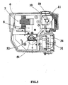
- Figure 5 is a sectional view of the housing of Figure 2 comprising the control device of the hydraulic actuator according to the invention.
- valve system in a boat.
- valves R each have their own hydraulic actuator 1.
- Each of these valve + hydraulic actuator assemblies are connected on the one hand by electrical cables 2 to a central electrical power supply system 3, and on the other hand by communication buses, that is to say data lines, to a central processor 4 controlling the central control and control of these valves R.
- the 5 control device of the hydraulic actuator consists of a housing 6 in which is enclosed a motor 7, a hydraulic block 8 and an electronic assembly 9 (in the form of printed circuit boards for example) for control and control local control device 5 of the hydraulic actuator.
- the hydraulic block 8 comprises a gear pump 10, an oil tank 11 and hydraulic circuits 12 comprising hydraulic valves 12 for connection with the hydraulic actuator 2 for hydraulic control thereof.
- the housing 6 common consists of a side wall 18 all around a bottom 14 and a top 15 which is fixed to the rest of the housing by screws 18 screwed into a rim 17 upper projecting inwards of the side wall 18.
- auxiliary compartment 29 in the common housing in which is received the portion 22 of local manual control of the control device.
- an opening 30 which is discovered by unscrewing a cap 31 which can be screwed tightly on the opening.
- This opening gives access to terminal blocks 32 for the connection of the electrical network and the data network respectively to the motor and to the electronic assembly 9 which are in the housing.
- These terminal blocks 33 are themselves enclosed in an auxiliary compartment 34, so that when the two power and data networks are connected, the rest of the housing is not subjected to a harsh environment, especially at a high humidity.
- the hydraulic pump is a gear pump.
- the local electronic control assembly 9 is constituted by printed circuit boards 40 on which electronic circuits are provided which make it possible to control the electric actuator as a function of a certain number of data obtained from several different sensors arranged either in the tap. either in the actuator or in the control device of the actuator.
- the data signals are either analog signals or digital signals.
- an analog-to-digital converter can be provided upstream of the box which transforms the signals into digital signals before sending them to the boards or printed circuit boards of the electronic assembly.
Landscapes
- Engineering & Computer Science (AREA)
- Mechanical Engineering (AREA)
- General Engineering & Computer Science (AREA)
- Physics & Mathematics (AREA)
- Fluid Mechanics (AREA)
- Analytical Chemistry (AREA)
- Chemical & Material Sciences (AREA)
- Fluid-Pressure Circuits (AREA)
- Fluid-Driven Valves (AREA)
- Supply Devices, Intensifiers, Converters, And Telemotors (AREA)
- Valve Device For Special Equipments (AREA)
- Indication Of The Valve Opening Or Closing Status (AREA)
- Servomotors (AREA)
Description
- La présente invention se rapporte à un système de robinetterie comportant un robinet, un actionneur électro-hydraulique pour l'actionnement du robinet et un dispositif de commande de l'actionneur, en particulier dans des environnements où un grand nombre de robinets sont chacun connectés d'une part à une source commune de courant électrique et d'autre part à un système central de traitement d'informations, en particulier dans des environnements dits difficiles, par exemple dans des navires. Le dispositif de commande est constitué d'un moteur électrique, d'un bloc hydraulique comportant une pompe hydraulique et un réservoir hydraulique, et d'un ensemble électronique de commande locale du robinet.
- Dans la technique antérieure, en particulier dans le domaine des constructions navales, on connaît déjà des systèmes de robinetterie de ce genre. Les dispositifs de commande de l'actionneur y sont généralement constitués en deux parties, à savoir une première partie comportant un boîtier, dans lequel se trouve le moteur électrique et le bloc hydraulique, comportant une pompe et un réservoir, et une deuxième partie comportant un cabinet ou petite armoire dans lequel se trouve un poste électronique de commande locale, notamment un PLC.
- Ce type de dispositif antérieur souffre de plusieurs inconvénients. En premier lieu ces dispositifs n'offrent pas beaucoup de fonctionnalités pour l'utilisateur final. En deuxième lieu, ces dispositifs sont très sensibles aux pannes, notamment lorsqu'ils sont installés dans des environnements dits difficiles, par exemple en milieu marin. Il s'avère d'ailleurs que plus il y a de fonctionnalités proposées par ces dispositifs et plus ils sont susceptibles de tomber en panne lors d'une exposition à des milieux difficiles. Enfin, ces dispositifs, par leur conception même en deux parties, sont volumineux, alors même que dans certains milieux difficiles comme par exemple dans des bateaux, navires ou autres installations confinées, la place disponible est un facteur important.
- La présente invention vise à surmonter ces inconvénients en proposant un nouveau dispositif de commande d'un actionneur électro-hydraulique d'un robinet, qui offre plus de fonctionnalités pour la commande et le contrôle du robinet, notamment, par exemple, la possibilité d'une commande manuelle en cas de défaillance du système central de commande, une surveillance de la température du moteur, de son ampérage et du temps de manoeuvre, une discrimination de fin de course, une surveillance du niveau d'huile, une indication du mouvement, etc., sans pour autant que la propension à tomber en panne du dispositif lorsqu'il est exposé à un milieu difficile, notamment dans un navire, n'augmente. Au contraire, suivant l'invention, le système est moins sensible aux environnements difficiles et notamment aux environnements marins, par exemple à un taux d'humidité élevé. Enfin, le système est moins encombrant que les systèmes de l'art antérieur, ce qui le rend particulièrement approprié pour une utilisation dans des bateaux ou navires. Un système de robinetterie suivant le préambule de la revendication 1 est connu de EP-A-0665381.
- Suivant l'invention, un système de robinetterie est tel que défini à la revendication 1.
- En prévoyant ainsi d'intégrer dans une même enveloppe le moteur électrique, le bloc hydraulique et l'ensemble électronique de commande, il n'est plus nécessaire pour obtenir de nombreuses fonctionnalités du système de prévoir de nombreux fils de transmission des données entre un cabinet de commande (dans lequel était disposé l'ensemble électronique de commande et contrôle local dans le cas de l'art antérieur) et un boîtier dans lequel se trouve le moteur. Or, si l'on prévoit dans les dispositifs antérieurs de nombreux fils pour transmettre des données en vue d'augmenter les fonctionnalités offertes à l'utilisateur final du robinet, il est nécessaire de prévoir de nombreuses ouvertures pour le passage de ces fils dans le boîtier comportant le moteur et le bloc hydraulique. La complexité et le nombre important de fils nécessaires pour transmettre les commandes liés à ces fonctionnalités sont alors tels que la fiabilité de ces fonctionnalités n'est pas d'un niveau acceptable. Suivant l'invention, au contraire, on peut en prévoir autant que l'on souhaite sans avoir à prévoir ni un grand nombre de fils, ni de nombreuses ouvertures de passage. Une commande locale, c'est-à-dire indépendante des systèmes centraux d'alimentation et de commande et de contrôle et affectée respectivement à l'actionneur, est ainsi possible. En particulier un opérateur ou un utilisateur peut commander manuellement le robinet à proximité immédiate de celui-ci en étant affecté à celui-ci.
- Suivant un perfectionnement de l'invention, le boîtier commun comporte une ouverture d'accès à une partie de l'ensemble électronique, notamment une partie pour une commande locale.
- En prévoyant ainsi une ouverture dans le boîtier pour permettre à l'utilisateur de venir commander en direct le système électronique de commande du robinet, on s'assure qu'il n'est pas nécessaire, dès que le système central tombe en panne et que l'on souhaite cependant faire fonctionner le robinet, d'avoir à retirer le boîtier complet et exposer ainsi l'ensemble à des conditions difficiles, notamment à un taux d'humidité élevé, ce qui est très néfaste pour les circuits électroniques, notamment des cartes à circuit imprimé.
- Suivant un perfectionnement de l'invention, le boîtier commun comporte une deuxième ouverture d'accès à la connectique pour le raccordement du moteur et de l'ensemble électronique aux réseaux de puissance électrique et de données. Ainsi, de même que dans le cas de l'ouverture d'accès à la partie de commande électronique, lorsque l'on effectue le branchement des deux réseaux de puissance électrique et de données en provenance du système central de commande et du réseau central d'alimentation en courant électrique, il n'est pas nécessaire de retirer le boîtier, et on évite ainsi de soumettre le dispositif de commande de l'actionneur à des conditions difficiles, notamment un taux d'humidité élevé.
- Suivant encore un perfectionnement de l'invention, le boîtier commun comporte un compartiment auxiliaire dans lequel se trouvent les bornes de raccordement pour la connectique, le compartiment auxiliaire étant rendu étanche vis-à-vis des fluides et poussières, par rapport au reste du boîtier.
- Ainsi, lorsque l'on effectue les branchements, on ne permet pas l'introduction à l'intérieur du boîtier et notamment sur les circuits intégrés de l'ensemble électronique, de poussière et autre humidité.
- Suivant un perfectionnement de l'invention, le boîtier comporte un deuxième compartiment auxiliaire dans lequel se trouve ladite partie de commande locale, notamment manuelle, de l'électronique.
- Suivant un mode de réalisation particulièrement avantageux, l'ensemble électronique comporte un microcontrôleur permettant d'intégrer les fonctions de contrôle et commande du moteur et de la pompe. On peut également prévoir des moyens destinés à effectuer l'interprétation des commandes de l'opérateur. On peut également prévoir un système de restitution des positions de fin de course, et les signaux électriques digitaux ou proportionnels. On peut également prévoir des moyens destinés à surveiller la température du moteur, l'ampérage du moteur ou le temps de manoeuvre du moteur. On peut également prévoir des moyens de discrimination de fin de course. On peut également prévoir des moyens de surveillance du niveau d'huile haut et bas. On peut également prévoir des moyens d'indication de mouvement. On peut également prévoir des moyens de diagnostic et de maintenance prédictive.
- De manière générale, on peut prévoir autant de fonctionnalités que l'on souhaite, sachant que l'on n'est plus limité par le fait d'avoir à faire passer autant de fils que de fonctionnalités entre un cabinet et un boîtier.
- La présente invention vise également un système de robinetterie comportant un actionneur électro-hydraulique et un dispositif de commande suivant l'invention. En particulier, le robinet peut être un robinet quart de tour ou un robinet linéaire.
- Au dessin, donné uniquement à titre d'exemple, la figure 1 est une vue d'ensemble d'un système de robinetterie dans un navire comportant un système central de traitement de données, un système central d'alimentation en courant et une pluralité de robinets et d'actionneurs électro-hydrauliques associés reliés chacun aux systèmes centraux.
- A la figure 2, il est représenté suivant une vue en perspective éclatée un boîtier commun suivant l'invention.
- A la figure 3, il est représenté le dispositif de commande de l'actionneur électro-hydraulique tel qu'incorporé dans le boîtier de la figure 2;
- La figure 4 est une vue d'ensemble de l'actionneur hydraulique, de son dispositif de commande et de son robinet associé.
- La figure 5 est une vue en coupe du boîtier de la figure 2 comportant le dispositif de commande de l'actionneur hydraulique suivant l'invention.
- A la figure 1, il est représenté un système de robinetterie dans un bateau. Plusieurs robinets R comportent chacun leur propre actionneur 1 hydraulique. Chacun de ces ensembles robinet+actionneur hydraulique sont reliés d'une part par des câbles électriques 2 à un système central de fourniture d'énergie électrique 3, et d'autre part, par des bus de communication, c'est-à-dire des lignes de transmission de données, à un processeur 4 central régissant la commande et le contrôle centraux de ces robinets R.
- A la figure 3, il est représenté de manière plus détaillée un dispositif de commande de l'actionneur hydraulique suivant l'invention. Le dispositif 5 de commande de l'actionneur hydraulique est constitué d'un boîtier 6 dans lequel est enfermé un moteur 7, un bloc 8 hydraulique et un ensemble 9 électronique (sous forme de plaquettes à circuits imprimés par exemple) permettant une commande et un contrôle locaux du dispositif 5 de commande de l'actionneur hydraulique. Le bloc 8 hydraulique comporte une pompe 10 à engrenage, un réservoir 11 à huile et des circuits 12 hydrauliques comportant des vannes 12 hydrauliques pour la liaison avec l'actionneur 2 hydraulique en vue de sa commande par l'hydraulique. Le boîtier 6 commun est constitué d'une paroi latérale 18 faisant tout le tour d'un fond 14 et d'un dessus 15 qui est fixé au reste du boîtier par des vis 18 vissées dans un rebord 17 supérieur faisant saillie vers l'intérieur de la paroi 18 latérale. Il est formé dans ce dessus 15 du boîtier 6 une ouverture 20 qui, par enlèvement d'un bouchon 21 adapté de manière étanche, permet l'accès à une partie 22 de commande manuelle locale du dispositif 5 de commande de l'actionneur et donc permet une commande locale du robinet. Ces commandes sont réalisées sous la forme de boutons poussoirs 23 que l'on peut pousser pour commander directement l'ensemble électronique de commande de l'actionneur.
- On peut prévoir une membrane 24 étanche et souple interposée entre les boutons poussoirs 28 et l'extérieur, de sorte que l'opérateur peut appuyer sur les boutons en appuyant sur la membrane qui transmet aux boutons 23 la poussée de l'opérateur, la membrane étant disposée de manière étanche, de sorte qu'ainsi, lorsque l'opérateur effectue la commande en poussant sur les boutons, il n'expose pas l'intérieur du boîtier commun à l'environnement extérieur difficile, notamment à un environnement à taux d'humidité élevé.
- En outre, il est prévu un compartiment 29 auxiliaire dans le boîtier commun dans lequel est reçu la partie 22 de commande manuelle locale du dispositif de commande.
- De même, dans la partie latérale, il est formé une ouverture 30 que l'on découvre en dévissant un bouchon 31 qui peut se visser de manière étanche sur l'ouverture. Cette ouverture donne accès à des blocs 32 à bornes pour le raccordement du réseau électrique et du réseau de données respectivement au moteur et à l'ensemble 9 électronique.qui se trouvent dans le boîtier. Ces blocs 33 à bornes sont eux-mêmes enfermés dans un compartiment 34 auxiliaire, de sorte que lorsque l'on effectue le raccordement des deux réseaux de puissance et de données, le reste du boîtier n'est pas soumis à un environnement difficile, notamment à un taux d'humidité élevé.
- La pompe hydraulique est une pompe à engrenage. On pourrait évidemment prévoir d'autres types de pompes suivant l'invention.
- L'ensemble 9 électronique de commande locale est constitué de cartes à circuit imprimé 40 sur lesquelles sont prévus des circuits électroniques permettant la commande de l'actionneur électrique en fonction d'un certain nombre de données obtenues de plusieurs capteurs différents disposés soit dans le robinet, soit dans l'actionneur, soit dans le dispositif de commande de l'actionneur.
- Ainsi il n'est plus nécessaire, pour fournir une fonctionnalité supplémentaire au robinet, de prévoir le passage d'un fil supplémentaire à travers le boîtier où se trouve le moteur et le bloc hydraulique. Comme l'ensemble électronique se trouve également dans le même boîtier, la liaison entre le moteur et le bloc hydraulique et cet ensemble se fait sans avoir à retirer le boîtier pour effectuer le branchement et sans avoir à prévoir des systèmes d'étanchéité pour chaque fil. Une seule et unique liaison pour les données traverse le boîtier, à savoir entre l'unité 4 centrale et l'ensemble 9 électronique. En outre, lorsque l'on souhaite commander localement le robinet, on n'a pas besoin de retirer le boîtier pour accéder à la partie de commande locale, notamment manuelle, de l'ensemble 9 électronique de commande.
- Les différentes fonctionnalités que l'on peut prévoir sont les suivantes (sans que cette liste ne soit exhaustive, ni limitative) :
- Microcontrôleur pour intégrer les fonctions de contrôle et commande locaux du moteur et de la pompe.
- Interprétation des commandes de l'utilisateur.
- Restitution des positions de fin de course.
- Surveillance de la température du moteur, de l'amperage ou de son temps de manoeuvre.
- Discrimination de fin de course.
- Surveillance du niveau d'huile, haut et bas.
- Indication du mouvement.
- Diagnostic et maintenance prédictives.
- Ces différentes fonctionnalités sont bien connues. Elles sont facilement mises en oeuvre par des circuits électroniques et des capteurs bien connus et que l'on ne décrit pas plus en détail ici, les circuits électroniques étant disposés dans l'ensemble 9 électronique.
- Les signaux de données sont soit de signaux analogiques, soit des signaux numériques. Dans le cas de signaux analogiques, on peut prévoir un convertisseur analogique/numérique en amont du boïtier qui transforme les signaux en signaux numériques avant de les envoyer aux cartes ou plaquettes à circuit imprimé de l'ensemble 9 électronique.
Claims (6)
- Système de robinetterie, comportant au moins deux robinets, chaque robinet étant actionné par un actionneur hydraulique qui lui est associé, chaque actionneur hydraulique étant commandé par un dispositif de commande, chaque dispositif de commande comportant un moteur alimentant une pompe hydraulique qui aspire du fluide hydraulique dans un réservoir hydraulique, et un ensemble électronique (9) de commande locale, les au moins deux moteurs étant alimentés en courant par une alimentation électrique centrale et étant également commandés centralement par une unité centrale de traitement de données à laquelle ils sont reliés par un bus de données, caractérisé en ce que :- pour chaque dispositif de commande, le moteur électrique, la pompe hydraulique, le réservoir et l'ensemble électronique sont enfermés dans une enveloppe commune, notamment un boîtier, de préférence de manière étanche aux fluides ; et le boîtier (16) commun comporte une ouverture (30) d'accès à la connectique pour le raccordement du moteur (7) et de l'ensemble (9) électronique aux réseaux (2, 3, 4) de puissance électrique et de données, et le boîtier (6) commun comporte un compartiment (34) auxiliaire dans lequel se trouvent les bornes (33) de raccordement pour la connectique, le compartiment auxiliaire (34) étant rendu étanche vis-à-vis des fluides et poussières, par rapport à l'ensemble (9) électronique et au reste du boîtier.
- Système de robinetterie suivant la revendication 1, caractérisé en ce que le boîtier (16) commun comporte une ouverture (20) d'accès à une partie (22) de l'ensemble (9) électronique, notamment une partie pour la commande locale.
- Système de robinetterie suivant l'une des revendications 1 ou 2, caractérisé en ce que le boîtier (6) comporte un deuxième compartiment (29) auxiliaire dans lequel se trouve ladite partie (22) de commande locale, notamment manuelle, de l'électronique, et il est possible de prévoir une membrane (24) étanche interposée entre ce compartiment (29) auxiliaire et l'extérieur du boîtier.
- Système de robinetterie suivant l'une des revendications 1 à 3, caractérisé en ce que les signaux échangés entre l'unité (4) centrale et chaque système sont des signaux numériques.
- Système de robinetterie suivant l'une des revendications 1 à 4, caractérisé en ce que les signaux échangés avec l'unité (4) centrale sont des signaux analogiques et il est prévu un convertisseur analogique numérique en amont du boîtier, entre celui-ci et l'unité (4) centrale.
- Navire, notamment bateau ou aéronef comportant un système de robinetterie suivant l'une des revendications 1 à 5.
Applications Claiming Priority (2)
| Application Number | Priority Date | Filing Date | Title |
|---|---|---|---|
| FR0213931 | 2002-11-07 | ||
| FR0213931A FR2847116A1 (fr) | 2002-11-07 | 2002-11-07 | Dispositif de commande d'un actionneur electro-hydraulique integre |
Publications (2)
| Publication Number | Publication Date |
|---|---|
| EP1418343A1 EP1418343A1 (fr) | 2004-05-12 |
| EP1418343B1 true EP1418343B1 (fr) | 2006-07-19 |
Family
ID=32104524
Family Applications (1)
| Application Number | Title | Priority Date | Filing Date |
|---|---|---|---|
| EP03292697A Expired - Lifetime EP1418343B1 (fr) | 2002-11-07 | 2003-10-29 | Dispositif de commande d'un actionneur électro-hydraulique intégré |
Country Status (11)
| Country | Link |
|---|---|
| EP (1) | EP1418343B1 (fr) |
| JP (1) | JP4589616B2 (fr) |
| KR (1) | KR101055681B1 (fr) |
| CN (1) | CN100398844C (fr) |
| AT (1) | ATE333593T1 (fr) |
| CY (1) | CY1106189T1 (fr) |
| DE (1) | DE60306868T2 (fr) |
| DK (1) | DK1418343T3 (fr) |
| ES (1) | ES2268298T3 (fr) |
| FR (1) | FR2847116A1 (fr) |
| PT (1) | PT1418343E (fr) |
Cited By (2)
| Publication number | Priority date | Publication date | Assignee | Title |
|---|---|---|---|---|
| DE102010007152A1 (de) | 2010-02-05 | 2011-08-11 | Hoerbiger Automatisierungstechnik Holding GmbH, 86956 | Fluidbetätigter Stellantrieb an einer Armatur |
| DE102010007137A1 (de) | 2010-02-05 | 2011-08-11 | Hoerbiger Automatisierungstechnik Holding GmbH, 86956 | Fluidbetätigter Stellantrieb an einer Armatur |
Families Citing this family (7)
| Publication number | Priority date | Publication date | Assignee | Title |
|---|---|---|---|---|
| DE102012203821A1 (de) | 2011-04-04 | 2012-10-04 | Schaeffler Technologies AG & Co. KG | Hydraulikmodul |
| DE202011107955U1 (de) * | 2011-11-16 | 2013-02-19 | Liebherr-Aerospace Lindenberg Gmbh | Elektrohydraulischer Stellantrieb |
| DE102013007927B4 (de) | 2013-05-10 | 2014-12-24 | Hoerbiger Automatisierungstechnik Holding Gmbh | Antriebseinheit |
| CN104533746B (zh) * | 2014-12-26 | 2016-09-14 | 东莞光洋信息科技有限公司 | 中央液压泵 |
| DE102016207659A1 (de) * | 2016-05-03 | 2017-11-09 | Robert Bosch Gmbh | Aktuatoreinrichtung für ein Fahrzeug, Bremssystem |
| CN105864482B (zh) * | 2016-06-01 | 2019-03-08 | 颜愚极 | 一种阀门执行系统 |
| CN114458818B (zh) * | 2022-02-14 | 2023-09-22 | 武汉市海益高端装备结构设计有限公司 | 一种便携式远程阀门电液集成控制系统 |
Family Cites Families (7)
| Publication number | Priority date | Publication date | Assignee | Title |
|---|---|---|---|---|
| JP2614128B2 (ja) * | 1990-02-01 | 1997-05-28 | 株式会社シー・オー・シー | 船舶用油圧バルブコントロールシステム |
| JPH03255201A (ja) * | 1990-11-30 | 1991-11-14 | Smc Corp | センサ出力伝送装置 |
| DE4120665A1 (de) * | 1991-06-22 | 1992-12-24 | Teves Gmbh Alfred | Elektromotorisch angetriebene hydraulikpumpe |
| DE59503395D1 (de) * | 1994-01-28 | 1998-10-08 | Pleiger Maschf Paul | Vorrichtung zum Betreiben von hydraulisch betätigten Armaturen |
| WO1998011357A1 (fr) * | 1996-09-12 | 1998-03-19 | Etrema Products, Inc. | Actionneur compact, unite de commande et appareil de pompage afferents |
| US6289259B1 (en) * | 1998-10-16 | 2001-09-11 | Husky Injection Molding Systems Ltd. | Intelligent hydraulic manifold used in an injection molding machine |
| JP3615459B2 (ja) * | 2000-04-18 | 2005-02-02 | 株式会社嶋田 | 油圧シリンダユニット |
-
2002
- 2002-11-07 FR FR0213931A patent/FR2847116A1/fr not_active Withdrawn
-
2003
- 2003-10-29 EP EP03292697A patent/EP1418343B1/fr not_active Expired - Lifetime
- 2003-10-29 DK DK03292697T patent/DK1418343T3/da active
- 2003-10-29 AT AT03292697T patent/ATE333593T1/de not_active IP Right Cessation
- 2003-10-29 ES ES03292697T patent/ES2268298T3/es not_active Expired - Lifetime
- 2003-10-29 PT PT03292697T patent/PT1418343E/pt unknown
- 2003-10-29 DE DE60306868T patent/DE60306868T2/de not_active Expired - Lifetime
- 2003-11-06 KR KR1020030078419A patent/KR101055681B1/ko not_active Expired - Fee Related
- 2003-11-07 JP JP2003378863A patent/JP4589616B2/ja not_active Expired - Fee Related
- 2003-11-07 CN CNB2003101142162A patent/CN100398844C/zh not_active Expired - Fee Related
-
2006
- 2006-10-04 CY CY20061101432T patent/CY1106189T1/el unknown
Cited By (5)
| Publication number | Priority date | Publication date | Assignee | Title |
|---|---|---|---|---|
| DE102010007152A1 (de) | 2010-02-05 | 2011-08-11 | Hoerbiger Automatisierungstechnik Holding GmbH, 86956 | Fluidbetätigter Stellantrieb an einer Armatur |
| WO2011095351A1 (fr) | 2010-02-05 | 2011-08-11 | Hoerbiger Automatisierungstechnik Holding Gmbh | Servomoteur actionné par un fluide dans une robinetterie |
| DE102010007137A1 (de) | 2010-02-05 | 2011-08-11 | Hoerbiger Automatisierungstechnik Holding GmbH, 86956 | Fluidbetätigter Stellantrieb an einer Armatur |
| WO2011095350A1 (fr) | 2010-02-05 | 2011-08-11 | Hoerbiger Automatisierungstechnik Holding Gmbh | Servomoteur actionné par un fluide dans une robinetterie |
| DE102010007152B4 (de) | 2010-02-05 | 2017-03-30 | Hoerbiger Automatisierungstechnik Holding Gmbh | Fluidbetätigter Stellantrieb an einer Armatur |
Also Published As
| Publication number | Publication date |
|---|---|
| KR20040041038A (ko) | 2004-05-13 |
| PT1418343E (pt) | 2006-11-30 |
| DK1418343T3 (da) | 2006-11-13 |
| ATE333593T1 (de) | 2006-08-15 |
| JP4589616B2 (ja) | 2010-12-01 |
| CN100398844C (zh) | 2008-07-02 |
| ES2268298T3 (es) | 2007-03-16 |
| EP1418343A1 (fr) | 2004-05-12 |
| DE60306868T2 (de) | 2007-03-01 |
| JP2004156785A (ja) | 2004-06-03 |
| KR101055681B1 (ko) | 2011-08-09 |
| FR2847116A1 (fr) | 2004-05-14 |
| DE60306868D1 (de) | 2006-08-31 |
| CY1106189T1 (el) | 2011-06-08 |
| CN1499085A (zh) | 2004-05-26 |
Similar Documents
| Publication | Publication Date | Title |
|---|---|---|
| EP1418343B1 (fr) | Dispositif de commande d'un actionneur électro-hydraulique intégré | |
| EP0351272B1 (fr) | Moteur électrique équipé d'un moyen de jonction modulaire | |
| FR2772203A1 (fr) | Dispositif d'interruption electrique comportant un module de communication | |
| CA2785918A1 (fr) | Systeme de commande d'un aeronef | |
| EP3441270B1 (fr) | Systeme de nettoyage d'une surface vitree de vehicule | |
| EP0415317B1 (fr) | Dispositif de sécurité anti-retour | |
| EP1376279A1 (fr) | Système de communication de sécurité. | |
| EP2873560A2 (fr) | Dispositif de pilotage d'une pluralité de blocs lumineux d'un véhicule automobile | |
| FR2660121A1 (fr) | Procede et dispositif pour un systeme de surveillance de commutateurs de prises de transformateurs a prises. | |
| US20140209825A1 (en) | System and method for remote control and monitoring of a valve | |
| EP3474419B1 (fr) | Servomoteur pour vanne ou vantelle industrielle avec carte de raccordement et connecteur | |
| FR2528524A1 (fr) | Dispositif actionneur de vanne | |
| FR2680629A1 (fr) | Dispositif de commande d'un reseau de moyens d'irrigation implantes dans une zone determinee. | |
| FR2688049A1 (fr) | Agencement pour la telecommande du fonctionnement d'une vanne a actionnement hydraulique et tete de puits de gisement petrolier. | |
| CN213512321U (zh) | 一种阀门电液驱动装置 | |
| EP0800248A1 (fr) | Dispositif de commande d'appareillage haute tension comportant un agencement synoptique | |
| EP1642050B1 (fr) | Architecture electrique d un dispositif de selection de vite sses pour une boite de vitesses automatique | |
| EP0947703B1 (fr) | Groupe motopompe submersible à dispositif de commande fixe sur l'enveloppe du moteur | |
| CA2081624A1 (fr) | Systeme servant au controle et a la surveillance de la production d'hydrocarbures, en surface ou sous-marine | |
| Qiu | Power Breakers for Control and Monitoring Subsea Cabled Observatory Instruments | |
| FR2725052A1 (fr) | Dispositif de telecommande d'organes, tels que des vannes, a actionnement hydraulique en milieu sous-marin | |
| EP4425721A1 (fr) | Fiche pour un connecteur sous-marin et méthode de changement de connexion sous-marine entre une fiche et un réceptacle | |
| FR2975544A1 (fr) | Installation de commande permettant de commander l'alimentation electrique d'une pluralite d'organes electriques en courant continu | |
| EP3881024B1 (fr) | Système lance-armes pour un navire submersible | |
| FR2646265A1 (fr) | Commutateur a distance de micro-ordinateur, par ligne telephonique |
Legal Events
| Date | Code | Title | Description |
|---|---|---|---|
| PUAI | Public reference made under article 153(3) epc to a published international application that has entered the european phase |
Free format text: ORIGINAL CODE: 0009012 |
|
| AK | Designated contracting states |
Kind code of ref document: A1 Designated state(s): AT BE BG CH CY CZ DE DK EE ES FI FR GB GR HU IE IT LI LU MC NL PT RO SE SI SK TR |
|
| AX | Request for extension of the european patent |
Extension state: AL LT LV MK |
|
| 17P | Request for examination filed |
Effective date: 20041112 |
|
| AKX | Designation fees paid |
Designated state(s): AT BE BG CH CY CZ DE DK EE ES FI FR GB GR HU IE IT LI LU MC NL PT RO SE SI SK TR |
|
| AXX | Extension fees paid |
Extension state: LT Payment date: 20041112 |
|
| 17Q | First examination report despatched |
Effective date: 20050203 |
|
| GRAP | Despatch of communication of intention to grant a patent |
Free format text: ORIGINAL CODE: EPIDOSNIGR1 |
|
| GRAS | Grant fee paid |
Free format text: ORIGINAL CODE: EPIDOSNIGR3 |
|
| GRAA | (expected) grant |
Free format text: ORIGINAL CODE: 0009210 |
|
| AK | Designated contracting states |
Kind code of ref document: B1 Designated state(s): AT BE BG CH CY CZ DE DK EE ES FI FR GB GR HU IE IT LI LU MC NL PT RO SE SI SK TR |
|
| AX | Request for extension of the european patent |
Extension state: LT |
|
| PG25 | Lapsed in a contracting state [announced via postgrant information from national office to epo] |
Ref country code: CZ Free format text: LAPSE BECAUSE OF FAILURE TO SUBMIT A TRANSLATION OF THE DESCRIPTION OR TO PAY THE FEE WITHIN THE PRESCRIBED TIME-LIMIT Effective date: 20060719 Ref country code: IT Free format text: LAPSE BECAUSE OF FAILURE TO SUBMIT A TRANSLATION OF THE DESCRIPTION OR TO PAY THE FEE WITHIN THE PRESCRIBED TIME-LIMIT;WARNING: LAPSES OF ITALIAN PATENTS WITH EFFECTIVE DATE BEFORE 2007 MAY HAVE OCCURRED AT ANY TIME BEFORE 2007. THE CORRECT EFFECTIVE DATE MAY BE DIFFERENT FROM THE ONE RECORDED. Effective date: 20060719 Ref country code: SK Free format text: LAPSE BECAUSE OF FAILURE TO SUBMIT A TRANSLATION OF THE DESCRIPTION OR TO PAY THE FEE WITHIN THE PRESCRIBED TIME-LIMIT Effective date: 20060719 Ref country code: SI Free format text: LAPSE BECAUSE OF FAILURE TO SUBMIT A TRANSLATION OF THE DESCRIPTION OR TO PAY THE FEE WITHIN THE PRESCRIBED TIME-LIMIT Effective date: 20060719 Ref country code: AT Free format text: LAPSE BECAUSE OF FAILURE TO SUBMIT A TRANSLATION OF THE DESCRIPTION OR TO PAY THE FEE WITHIN THE PRESCRIBED TIME-LIMIT Effective date: 20060719 |
|
| REG | Reference to a national code |
Ref country code: GB Ref legal event code: FG4D Free format text: NOT ENGLISH |
|
| REG | Reference to a national code |
Ref country code: CH Ref legal event code: EP |
|
| REG | Reference to a national code |
Ref country code: IE Ref legal event code: FG4D Free format text: LANGUAGE OF EP DOCUMENT: FRENCH |
|
| REF | Corresponds to: |
Ref document number: 60306868 Country of ref document: DE Date of ref document: 20060831 Kind code of ref document: P |
|
| REG | Reference to a national code |
Ref country code: RO Ref legal event code: EPE |
|
| GBT | Gb: translation of ep patent filed (gb section 77(6)(a)/1977) |
Effective date: 20060928 |
|
| REG | Reference to a national code |
Ref country code: SE Ref legal event code: TRGR |
|
| REG | Reference to a national code |
Ref country code: DK Ref legal event code: T3 |
|
| REG | Reference to a national code |
Ref country code: GR Ref legal event code: EP Ref document number: 20060403516 Country of ref document: GR |
|
| REG | Reference to a national code |
Ref country code: PT Ref legal event code: SC4A Free format text: AVAILABILITY OF NATIONAL TRANSLATION Effective date: 20061004 |
|
| REG | Reference to a national code |
Ref country code: EE Ref legal event code: FG4A Ref document number: E000698 Country of ref document: EE Effective date: 20060927 |
|
| REG | Reference to a national code |
Ref country code: ES Ref legal event code: FG2A Ref document number: 2268298 Country of ref document: ES Kind code of ref document: T3 |
|
| PLBE | No opposition filed within time limit |
Free format text: ORIGINAL CODE: 0009261 |
|
| STAA | Information on the status of an ep patent application or granted ep patent |
Free format text: STATUS: NO OPPOSITION FILED WITHIN TIME LIMIT |
|
| 26N | No opposition filed |
Effective date: 20070420 |
|
| REG | Reference to a national code |
Ref country code: CH Ref legal event code: PL |
|
| PG25 | Lapsed in a contracting state [announced via postgrant information from national office to epo] |
Ref country code: LU Free format text: LAPSE BECAUSE OF NON-PAYMENT OF DUE FEES Effective date: 20061029 Ref country code: CH Free format text: LAPSE BECAUSE OF NON-PAYMENT OF DUE FEES Effective date: 20071031 Ref country code: HU Free format text: LAPSE BECAUSE OF FAILURE TO SUBMIT A TRANSLATION OF THE DESCRIPTION OR TO PAY THE FEE WITHIN THE PRESCRIBED TIME-LIMIT Effective date: 20070120 Ref country code: LI Free format text: LAPSE BECAUSE OF NON-PAYMENT OF DUE FEES Effective date: 20071031 |
|
| PGFP | Annual fee paid to national office [announced via postgrant information from national office to epo] |
Ref country code: RO Payment date: 20100927 Year of fee payment: 8 |
|
| PGFP | Annual fee paid to national office [announced via postgrant information from national office to epo] |
Ref country code: EE Payment date: 20121022 Year of fee payment: 10 Ref country code: IE Payment date: 20121019 Year of fee payment: 10 Ref country code: CY Payment date: 20121025 Year of fee payment: 10 Ref country code: BG Payment date: 20121031 Year of fee payment: 10 Ref country code: BE Payment date: 20121026 Year of fee payment: 10 |
|
| PGFP | Annual fee paid to national office [announced via postgrant information from national office to epo] |
Ref country code: GB Payment date: 20121024 Year of fee payment: 10 Ref country code: SE Payment date: 20121024 Year of fee payment: 10 |
|
| REG | Reference to a national code |
Ref country code: LT Ref legal event code: MM9D Effective date: 20121029 |
|
| BERE | Be: lapsed |
Owner name: *KSB S.A.S Effective date: 20131031 |
|
| REG | Reference to a national code |
Ref country code: SE Ref legal event code: EUG |
|
| REG | Reference to a national code |
Ref country code: EE Ref legal event code: MM4A Ref document number: E000698 Country of ref document: EE Effective date: 20131031 |
|
| GBPC | Gb: european patent ceased through non-payment of renewal fee |
Effective date: 20131029 |
|
| REG | Reference to a national code |
Ref country code: IE Ref legal event code: MM4A |
|
| PG25 | Lapsed in a contracting state [announced via postgrant information from national office to epo] |
Ref country code: EE Free format text: LAPSE BECAUSE OF NON-PAYMENT OF DUE FEES Effective date: 20131031 Ref country code: GB Free format text: LAPSE BECAUSE OF NON-PAYMENT OF DUE FEES Effective date: 20131029 |
|
| PG25 | Lapsed in a contracting state [announced via postgrant information from national office to epo] |
Ref country code: CY Free format text: LAPSE BECAUSE OF NON-PAYMENT OF DUE FEES Effective date: 20131029 Ref country code: RO Free format text: LAPSE BECAUSE OF NON-PAYMENT OF DUE FEES Effective date: 20131029 Ref country code: SE Free format text: LAPSE BECAUSE OF NON-PAYMENT OF DUE FEES Effective date: 20131030 Ref country code: BG Free format text: LAPSE BECAUSE OF NON-PAYMENT OF DUE FEES Effective date: 20140630 |
|
| PG25 | Lapsed in a contracting state [announced via postgrant information from national office to epo] |
Ref country code: BG Free format text: LAPSE BECAUSE OF NON-PAYMENT OF DUE FEES Effective date: 20131031 Ref country code: BE Free format text: LAPSE BECAUSE OF NON-PAYMENT OF DUE FEES Effective date: 20131031 |
|
| PG25 | Lapsed in a contracting state [announced via postgrant information from national office to epo] |
Ref country code: IE Free format text: LAPSE BECAUSE OF NON-PAYMENT OF DUE FEES Effective date: 20131029 Ref country code: BG Free format text: LAPSE BECAUSE OF NON-PAYMENT OF DUE FEES Effective date: 20140930 |
|
| REG | Reference to a national code |
Ref country code: FR Ref legal event code: PLFP Year of fee payment: 13 |
|
| PGFP | Annual fee paid to national office [announced via postgrant information from national office to epo] |
Ref country code: PT Payment date: 20150925 Year of fee payment: 13 |
|
| PGFP | Annual fee paid to national office [announced via postgrant information from national office to epo] |
Ref country code: DK Payment date: 20151022 Year of fee payment: 13 |
|
| PGFP | Annual fee paid to national office [announced via postgrant information from national office to epo] |
Ref country code: TR Payment date: 20151027 Year of fee payment: 13 Ref country code: GR Payment date: 20151027 Year of fee payment: 13 Ref country code: FI Payment date: 20151027 Year of fee payment: 13 Ref country code: IT Payment date: 20151030 Year of fee payment: 13 |
|
| PGFP | Annual fee paid to national office [announced via postgrant information from national office to epo] |
Ref country code: FR Payment date: 20151022 Year of fee payment: 13 Ref country code: NL Payment date: 20151019 Year of fee payment: 13 Ref country code: ES Payment date: 20151013 Year of fee payment: 13 Ref country code: MC Payment date: 20151028 Year of fee payment: 13 |
|
| REG | Reference to a national code |
Ref country code: DK Ref legal event code: EBP Effective date: 20161031 |
|
| REG | Reference to a national code |
Ref country code: NL Ref legal event code: MM Effective date: 20161101 |
|
| PG25 | Lapsed in a contracting state [announced via postgrant information from national office to epo] |
Ref country code: MC Free format text: LAPSE BECAUSE OF NON-PAYMENT OF DUE FEES Effective date: 20161031 |
|
| REG | Reference to a national code |
Ref country code: FR Ref legal event code: ST Effective date: 20170630 |
|
| PG25 | Lapsed in a contracting state [announced via postgrant information from national office to epo] |
Ref country code: FI Free format text: LAPSE BECAUSE OF NON-PAYMENT OF DUE FEES Effective date: 20161029 Ref country code: FR Free format text: LAPSE BECAUSE OF NON-PAYMENT OF DUE FEES Effective date: 20161102 Ref country code: GR Free format text: LAPSE BECAUSE OF NON-PAYMENT OF DUE FEES Effective date: 20170504 |
|
| PG25 | Lapsed in a contracting state [announced via postgrant information from national office to epo] |
Ref country code: PT Free format text: LAPSE BECAUSE OF NON-PAYMENT OF DUE FEES Effective date: 20170502 Ref country code: NL Free format text: LAPSE BECAUSE OF NON-PAYMENT OF DUE FEES Effective date: 20161101 |
|
| PG25 | Lapsed in a contracting state [announced via postgrant information from national office to epo] |
Ref country code: IT Free format text: LAPSE BECAUSE OF NON-PAYMENT OF DUE FEES Effective date: 20161029 |
|
| PG25 | Lapsed in a contracting state [announced via postgrant information from national office to epo] |
Ref country code: DK Free format text: LAPSE BECAUSE OF NON-PAYMENT OF DUE FEES Effective date: 20161031 |
|
| PG25 | Lapsed in a contracting state [announced via postgrant information from national office to epo] |
Ref country code: ES Free format text: LAPSE BECAUSE OF NON-PAYMENT OF DUE FEES Effective date: 20161030 |
|
| REG | Reference to a national code |
Ref country code: ES Ref legal event code: FD2A Effective date: 20181122 |
|
| PG25 | Lapsed in a contracting state [announced via postgrant information from national office to epo] |
Ref country code: TR Free format text: LAPSE BECAUSE OF NON-PAYMENT OF DUE FEES Effective date: 20161029 |
|
| PGFP | Annual fee paid to national office [announced via postgrant information from national office to epo] |
Ref country code: DE Payment date: 20221117 Year of fee payment: 20 |
|
| REG | Reference to a national code |
Ref country code: DE Ref legal event code: R071 Ref document number: 60306868 Country of ref document: DE |