EP1417992A1 - Gaming machine - Google Patents
Gaming machine Download PDFInfo
- Publication number
- EP1417992A1 EP1417992A1 EP03024998A EP03024998A EP1417992A1 EP 1417992 A1 EP1417992 A1 EP 1417992A1 EP 03024998 A EP03024998 A EP 03024998A EP 03024998 A EP03024998 A EP 03024998A EP 1417992 A1 EP1417992 A1 EP 1417992A1
- Authority
- EP
- European Patent Office
- Prior art keywords
- decorative panel
- frame
- cabinet
- gaming machine
- door
- Prior art date
- Legal status (The legal status is an assumption and is not a legal conclusion. Google has not performed a legal analysis and makes no representation as to the accuracy of the status listed.)
- Granted
Links
- 230000002093 peripheral effect Effects 0.000 claims description 14
- 238000003780 insertion Methods 0.000 claims description 4
- 230000037431 insertion Effects 0.000 claims description 4
- 238000003825 pressing Methods 0.000 description 6
- 238000005034 decoration Methods 0.000 description 5
- 230000000694 effects Effects 0.000 description 3
- 230000000903 blocking effect Effects 0.000 description 2
- 239000000463 material Substances 0.000 description 2
- 229920003002 synthetic resin Polymers 0.000 description 2
- 239000000057 synthetic resin Substances 0.000 description 2
- 241001391944 Commicarpus scandens Species 0.000 description 1
- 229910052782 aluminium Inorganic materials 0.000 description 1
- XAGFODPZIPBFFR-UHFFFAOYSA-N aluminium Chemical compound [Al] XAGFODPZIPBFFR-UHFFFAOYSA-N 0.000 description 1
- 239000011521 glass Substances 0.000 description 1
- 230000001678 irradiating effect Effects 0.000 description 1
- 238000004519 manufacturing process Methods 0.000 description 1
- 239000007769 metal material Substances 0.000 description 1
- 238000000034 method Methods 0.000 description 1
- 229920003217 poly(methylsilsesquioxane) Polymers 0.000 description 1
Images



Classifications
-
- G—PHYSICS
- G07—CHECKING-DEVICES
- G07F—COIN-FREED OR LIKE APPARATUS
- G07F17/00—Coin-freed apparatus for hiring articles; Coin-freed facilities or services
- G07F17/32—Coin-freed apparatus for hiring articles; Coin-freed facilities or services for games, toys, sports, or amusements
- G07F17/3202—Hardware aspects of a gaming system, e.g. components, construction, architecture thereof
- G07F17/3216—Construction aspects of a gaming system, e.g. housing, seats, ergonomic aspects
-
- A—HUMAN NECESSITIES
- A63—SPORTS; GAMES; AMUSEMENTS
- A63F—CARD, BOARD, OR ROULETTE GAMES; INDOOR GAMES USING SMALL MOVING PLAYING BODIES; VIDEO GAMES; GAMES NOT OTHERWISE PROVIDED FOR
- A63F13/00—Video games, i.e. games using an electronically generated display having two or more dimensions
- A63F13/20—Input arrangements for video game devices
- A63F13/24—Constructional details thereof, e.g. game controllers with detachable joystick handles
-
- A—HUMAN NECESSITIES
- A63—SPORTS; GAMES; AMUSEMENTS
- A63F—CARD, BOARD, OR ROULETTE GAMES; INDOOR GAMES USING SMALL MOVING PLAYING BODIES; VIDEO GAMES; GAMES NOT OTHERWISE PROVIDED FOR
- A63F2300/00—Features of games using an electronically generated display having two or more dimensions, e.g. on a television screen, showing representations related to the game
- A63F2300/10—Features of games using an electronically generated display having two or more dimensions, e.g. on a television screen, showing representations related to the game characterized by input arrangements for converting player-generated signals into game device control signals
- A63F2300/1043—Features of games using an electronically generated display having two or more dimensions, e.g. on a television screen, showing representations related to the game characterized by input arrangements for converting player-generated signals into game device control signals being characterized by constructional details
-
- Y—GENERAL TAGGING OF NEW TECHNOLOGICAL DEVELOPMENTS; GENERAL TAGGING OF CROSS-SECTIONAL TECHNOLOGIES SPANNING OVER SEVERAL SECTIONS OF THE IPC; TECHNICAL SUBJECTS COVERED BY FORMER USPC CROSS-REFERENCE ART COLLECTIONS [XRACs] AND DIGESTS
- Y10—TECHNICAL SUBJECTS COVERED BY FORMER USPC
- Y10S—TECHNICAL SUBJECTS COVERED BY FORMER USPC CROSS-REFERENCE ART COLLECTIONS [XRACs] AND DIGESTS
- Y10S362/00—Illumination
- Y10S362/806—Ornamental or decorative
Definitions
- the present invention relates to a gaming machine.
- a console to be operatedbygamers and a display unit for displaying details of games are disposed at a position relatively close to the eye level of gamers, whereas the above-mentioned decorative panel is incorporated above and/or below these units.
- Suchadecorativepanelhadbeen fixed beforehand to a frame covering surroundings of the decorative panel, and then the frame has been attached to a gaming machine (see, for example, Japanese Patent Application Laid-Open No. 2001-631).
- Examples of methods for mounting the frame to the gaming machine include those fitting individual sides of the frame into the gamingmachine, those attaching the frame to the gamingmachine in a door-like fashion, etc.
- decorative panels are often illuminated with a light source from behind for their decoration.
- the illuminated parts do not employ aggregates and the like for increasing the strength of the panel and are relatively easy to break. Therefore, the decorative panel must be replaced alone when broken.
- the decorative panel For securing the above-mentioned decorative panel to a frame beforehand, however, the decorative panel must be fastened with screws and the like at its peripheral parts in contact with the frame.
- the gaming machine in accordance with the present invention comprises a cabinet; a light source disposedwi thin the cabinet; andadecorativepanel, disposed in front of the light source, including one surface for receiving light from the light source; and the gamingmachine further comprises support means, provided with the cabinet, for supporting the decorative panel from the one surface; and a frame, detachably attached to the cabinet, including a back face for supporting the decorative panel from the other surface thereof opposite from the one surface in a state where the frame is secured to the cabinet.
- the decorative panel When the frame is fixed to the cabinet in this configuration, the decorative panel is supported by the frame and the support means, whereby no parts for securing the decorative panel to the frame are necessary. This can reduce the cost of parts and the time and trouble to replace the decorative panel.
- a decorative panel had been fixed beforehand with screws and the like to a frame for securing the decorative panel, and then the frame has been secured to the cabinet so that the decorative panel is mounted to the cabinet.
- a configuration requires a large number of parts for securing the decorative panel and the frame to each other.
- the decorative panel has been very hard to remove and attach when needed to be replaced.
- the present invention is configured such that the decorative panel is not fixed to the frame beforehand, but is secured as being held between the frame and the cabinet at the time when fixing the frame to the cabinet.
- This configuration necessitates few parts for securing the decorative panel to the frame. Also, it allows the decorative panel to be replaced quite easily.
- the support means supports the decorative panel while in a state in contact with only a peripheral part of the one surface of the decorative panel.
- This configuration makes it possible to support the decorative panel by the peripheral part thereof alone, whereby functions of the decorative panel can fully be exhibited without blocking the light illuminating the decorative panel from the light source.
- the frame further comprises panel safety means, disposed at a position opposing a bottom end of the decorative panel, for preventing the decorative panel from dropping out.
- the frame is provided with panel safety means for preventing the decorative panel from dropping out, the decorative panel does not drop out even when the frame is not secured to the cabinet. Therefore, the decorative panel can be prevented from breaking because of dropping and the like. As a consequence, operations for opening/closing the frame for replacing the decorative panel and the light source, etc., can be carried out safely.
- the frame is formed with an insertion opening for receiving the decorative panel from a bottom end thereof.
- the decorative panel When the decorative panel is inserted from the insertion opening in this configuration, the decorative panel can be accommodated in a space provided beforehand between the frame and the safety means, whereby it becomes easier to handle the decorative panel.
- the inserting position may be located at a side face.
- a shaft is attached to the cabinet, whereas one end of the frame is axially supported by the shaft.
- This configuration allows the frame to rotate about the shaft, which makes it easier to secure the frame to the cabinet or release the frame from the cabinet.
- the gaming machine of the present invention further comprises a cover, attached to the back face of the frame so as to expose a peripheral part of the one surface of the decorative panel, for covering the light source while having an opening directed to the frame; whereas a space for accommodating the decorative panel is formed between the cover and the frame; the support means supporting the decorative panel while in a state in contact with only the peripheral part in one surface of the decorative panel.
- the decorative panel can be accommodated in the space between the cover for covering the light source and the frame, whereby the decorative panel can be prevented from toppling down when securing the frame to the cabinet or releasing the frame from the cabinet.
- Fig. 1 is a front view of the slot machine 1.
- words indicating directions will be used with reference to the state shown in Fig. 1. Namely, the state in which the gaming machine 1 stands erect is taken as a reference, and the direction from a cabinet 2 to a top frame 4 is defined as upward. The direction from the gaming machine 1 to a position where a gamer plays a game is defined as forward or front side.
- a door 3 is attached to the cabinet 2 so as to be able to open and close.
- the top frame 4 is attached to the upper side of the cabinet 2.
- a decorative panel 41 is provided in front of the top frame 4.
- An image display unit 21 for displaying game information is placed within the cabinet 2.
- a window is formed in the upper part of the door 3, whereas a transparent plate for making the display of the image display unit 21 viewable or protecting the image display unit 21 is attached to the window.
- Formed on both sides of the window are speaker grills for making it easy to hear sound effects or incidental music generated according to states of games.
- a control panel 5 Disposed at the center part on the front face of the door 3 is a control panel 5 in a projecting form. Namely, the control panel 5 projects forward from the door 3. In the slope on the right side of the control panel 5; various operating buttons are arranged together with a coin slot 51 for inserting coins.
- a bill guide 52 Provided on the left side of the control panel 5 is a bill guide 52 for guiding bills into a bill identifier (bill validator) accommodated in the cabinet 2.
- the frame 6 is connected to the door 3 in a freely opening and closing fashion.
- the frame 6 incorporates a decorative panel 61 therein.
- the decorative panel 61 is provided with a decoration indicating the kind of the gaming machine and the like.
- the decorative panel 41 of the top frame 4 located above the screen of the image display unit 21 is also provided with the decoration in an easily viewable fashion.
- a coin tray 30 for receiving coins.
- Fig. 2 is a view showing a state where the frame 6 is opened, the frame 6 being seen from its back face.
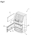
- Fig. 5 is a perspective view showing a state where the frame 6 is opened, the frame 6 being seen from its back face.
- the top frame 4 is not shown in Fig. 5.
- a shaft 64 is disposed at the right side of the frame 6, whereby the frame 6 is rotatably connected to the door 3.
- a cover 62 is attached to the back face of the frame 6 so that the back face is substantially covered therewith.
- the upper end of the cover 62 is set such that a support part 3A in the door 3, which will be explained later, can enter.
- the lower end of the cover 62 is set such that a support part 3A in the door 3 can enter.
- a chain 6B has one end connected to the cover 62, and the other end connected to the door 3. The chain 6B is used for preventing the frame 6 from opening from the door 3 by a predetermined angle or greater.
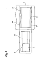
- Fig. 3 is a view showing a state where the frame 6 is opened. This is a view showing a state where both the door 3 and the frame 6 are seen from behind. As shown in Fig. 3, a pair of support parts 3A bent to project toward the frame 6 are formed in the door 3. A pressing member 31 such as sponge is bonded to each support part 3A, for example. When the frame 6 is closed, the upper face of the frame 6 is placed near the bottom face of the control panel 5.
- Fig. 4 is an exploded perspective view of the frame 6.
- the decorative panel 61 has a rectangular form, and is constituted by a light-transparent glass or synthetic resin material.
- the frame 6 includes a frame plate 63.
- the frame plate 63 comprises a front part disposed so as to support the peripheral part of the surface of the decorative panel 61, right and left sides extending in directions intersecting the front part, and an edge 632 extending from the bottom end of the front part into a direction intersecting the front part.
- the upper end of the frame plate 63 is formed with an insertion opening for inserting the decorative panel 61.
- the frame plate 63 is integrally formed from a lightweight metal material or a hard lightweight synthetic resin material.
- the decorative panel 61 is accommodated in a space between the sides of the frame plate 63.
- a window 631 is formed in the front part of the frame plate 63 so that the decoration of the decorative panel 61 is visible when the decorative panel 61 is accommodated in the frame plate 63.
- the edge 632 extends from the frame plate 63 at the bottom part thereof.
- a plate 6A1 for securing a cylinder lock 6A to the frame plate 63 is disposed at the left side of the frame plate 63.
- a stopper 6A2 for locking the frame 6 to the door 3.
- a through hole 633 is formed in the right side of the frame plate 63.
- a shaft 64 is inserted into the through hole 633, whereby the frame plate 63 is rotatably connected to the door 3.
- the cover 62 is fixed to the frame plate 63.
- a pair of sockets 65A, 65B are attached to the inner wall of the cover 62, whereas a fluorescent lamp 65 is attached to the sockets 65A, 65B.
- a gap in which the thickness of the decorative panel 61 can just be inserted is formed between the inner face of the cover 62 and the back wall of the frame plate 63.
- the cover 62 covers the fluorescent lamp 65 while having an opening directed to the back face of the frame plate 63.
- the fluorescent lamp 65 is located within the door 3.
- a gap for accommodating the decorative panel 61 is formed between the cover 62 and the frame plate 63.
- the decorative panel 61 accommodated in the space has a rear face for receiving the light from the fluorescent lamp 65 and a front face for emitting thus received light.
- the cover 62 is attached to the back face of the frame 63 so as to expose the upper and lower end parts of the back face of the decorative panel 61.
- the edge 632 for preventing the decorative panel 61 from dropping out extends from the bottom part of the frame plate 63.
- a gap in which the thickness of the decorative panel 61 can just be inserted is formed between the inner face of the cover 62 and the back wall of the frame plate 63.
- the bottom face of the control panel 5 prevents the decorative panel 61 from projecting.
- the foregoing configuration generates a state in which the decorative panel 61 is accommodated in the frame 6. Namely, the frame plate 63 accommodates, together with the cover 62 attached thereto, the decorative panel 61, thereby preventing the decorative panel plate 61 from dropping out and toppling down.
- the decorative panel 61 is not completely secured by the foregoing alone, but is in an unstable state.
- the pair of pressing members 31 bonded to the support parts 3A of the door 3 press the upper and lower peripheral parts in the rear face of the decorative panel 61.
- peripheral parts in the front face of the decorative panel 61 come into contact with the back face of the frame plate 63.
- the support parts 3A of the door 3 and the frame plate 63, with the pressing members 31 interposed therebetween hold and support the decorative panel 61 therebetween.
- the decorative panel 61 is placed in a stable state.
- the support parts 3A of the door 3 and the pressing members 31 constitute support means.
- the decorative panel 61 attains a free state, which makes it easier for the decorative panel 61 to be pulled out from the upper side.
- the decorative panel 61 can be inserted/pulled from the upper side of the frame plate 63, a side face of the frame plate 63 may be opened such that the decorative panel 61 can be inserted in/pulled out sideways.
- the pressing members 31 bonded to the support parts 3A of the door 3 press the peripheral parts of the decorativepanel 61 in the vicinityof thebottom face thereof as mentioned above.
- the configuration that "the support means supports the decorative panel while in a state in contact with only a peripheral part of the decorative panel” makes it possible to support the decorative panel 61 from behind at only the peripheral part thereof, whereby functions of the decorative panel can fully be exhibited without blocking the light illuminating the decorative panel from the fluorescent panel 65.
- the light irradiating means is not limited to the fluorescent lamp. Any light illuminating means can be used as long as the decorative panel is illuminated from inside thereby.
- the cover 62 is constitutedby a silver-coloredmaterial such as aluminum, so that the backscattering light of the fluorescent lamp 65 is reflected toward the decorative panel 61, which is effective in that the decorative panel 61 becomes brighter than in the case with no reflection by the cover 62.
- the decorative panel 41 of the top frame 4 is brightly illuminated with an internal light source, whereby the existence of the slot machine 1 is shown up by the light-emitting screen of the display unit 21 as well as effects of the decorative panels 41, 61 disposed thereabove and thereunder.
Landscapes
- Engineering & Computer Science (AREA)
- Multimedia (AREA)
- Physics & Mathematics (AREA)
- General Physics & Mathematics (AREA)
- Human Computer Interaction (AREA)
- Slot Machines And Peripheral Devices (AREA)
- Pharmaceuticals Containing Other Organic And Inorganic Compounds (AREA)
- Memory System Of A Hierarchy Structure (AREA)
Abstract
Description
- The present invention relates to a gaming machine.
- In general, slot machines, video slot machines, and the like placed in casinos and arcades are provided with decorations by which kinds of gamingmachines are discernible at a glance even from a distance. However, decorating a cabinet itself is problematic in that the cabinet loses its versatility, so that it fails to be reused, increases the manufacturing cost, and so forth. Therefore, in this regard, many gaming machines are decorated such that a semitransparent decorative panel is fitted therein and electrically illuminated from behind so as to make designs formed on the panel visible.
- Specifically, a console to be operatedbygamers and a display unit for displaying details of games are disposed at a position relatively close to the eye level of gamers, whereas the above-mentioned decorative panel is incorporated above and/or below these units.
- Conventionally, suchadecorativepanelhadbeen fixed beforehand to a frame covering surroundings of the decorative panel, and then the frame has been attached to a gaming machine (see, for example, Japanese Patent Application Laid-Open No. 2001-631). Examples of methods for mounting the frame to the gaming machine include those fitting individual sides of the frame into the gamingmachine, those attaching the frame to the gamingmachine in a door-like fashion, etc.
- However, decorative panels are often illuminated with a light source from behind for their decoration. The illuminated parts do not employ aggregates and the like for increasing the strength of the panel and are relatively easy to break. Therefore, the decorative panel must be replaced alone when broken.
- On the other hand, though the cabinet of such a gaming machine is often reused as it is as mentioned above, its decorative panel must be replaced if a different game is to be installed therein.
- For securing the above-mentioned decorative panel to a frame beforehand, however, the decorative panel must be fastened with screws and the like at its peripheral parts in contact with the frame.
- Therefore, it takes too much time and trouble to remove and attach the decorative panel, and requires a large number of parts for attachment. These parts and manpower in operations have been expensive.
- In view of the foregoingproblems, it is an obj ect of the present invention to provide a gaming machine in which the number of parts for securing a decorative panel is small, whereas the decorative panel is easy to attach thereto and detach therefrom.
- The gaming machine in accordance with the present invention comprises a cabinet; a light source disposedwi thin the cabinet; andadecorativepanel, disposed in front of the light source, including one surface for receiving light from the light source; and the gamingmachine further comprises support means, provided with the cabinet, for supporting the decorative panel from the one surface; and a frame, detachably attached to the cabinet, including a back face for supporting the decorative panel from the other surface thereof opposite from the one surface in a state where the frame is secured to the cabinet.
- When the frame is fixed to the cabinet in this configuration, the decorative panel is supported by the frame and the support means, whereby no parts for securing the decorative panel to the frame are necessary. This can reduce the cost of parts and the time and trouble to replace the decorative panel.
- In conventional gaming machines, a decorative panel had been fixed beforehand with screws and the like to a frame for securing the decorative panel, and then the frame has been secured to the cabinet so that the decorative panel is mounted to the cabinet. However, such a configuration requires a large number of parts for securing the decorative panel and the frame to each other. Further, the decorative panel has been very hard to remove and attach when needed to be replaced.
- Therefore, the present invention is configured such that the decorative panel is not fixed to the frame beforehand, but is secured as being held between the frame and the cabinet at the time when fixing the frame to the cabinet. This configuration necessitates few parts for securing the decorative panel to the frame. Also, it allows the decorative panel to be replaced quite easily.
- Preferably, in the gaming machine of the present invention, the support means supports the decorative panel while in a state in contact with only a peripheral part of the one surface of the decorative panel.
- This configuration makes it possible to support the decorative panel by the peripheral part thereof alone, whereby functions of the decorative panel can fully be exhibited without blocking the light illuminating the decorative panel from the light source.
- Preferably, in the gamingmachine of the present invention, the frame further comprises panel safety means, disposed at a position opposing a bottom end of the decorative panel, for preventing the decorative panel from dropping out.
- Since the frame is provided with panel safety means for preventing the decorative panel from dropping out, the decorative panel does not drop out even when the frame is not secured to the cabinet. Therefore, the decorative panel can be prevented from breaking because of dropping and the like. As a consequence, operations for opening/closing the frame for replacing the decorative panel and the light source, etc., can be carried out safely.
- Preferably, in the gamingmachine of the present invention, the frame is formed with an insertion opening for receiving the decorative panel from a bottom end thereof.
- When the decorative panel is inserted from the insertion opening in this configuration, the decorative panel can be accommodated in a space provided beforehand between the frame and the safety means, whereby it becomes easier to handle the decorative panel.
- Though the decorative panel is inserted from the upper face of the frame in the configuration mentioned above, the inserting position may be located at a side face.
- Preferably, in the gamingmachine of the present invention, a shaft is attached to the cabinet, whereas one end of the frame is axially supported by the shaft. This configuration allows the frame to rotate about the shaft, which makes it easier to secure the frame to the cabinet or release the frame from the cabinet.
- Preferably, the gaming machine of the present invention further comprises a cover, attached to the back face of the frame so as to expose a peripheral part of the one surface of the decorative panel, for covering the light source while having an opening directed to the frame; whereas a space for accommodating the decorative panel is formed between the cover and the frame; the support means supporting the decorative panel while in a state in contact with only the peripheral part in one surface of the decorative panel. In this configuration, the decorative panel can be accommodated in the space between the cover for covering the light source and the frame, whereby the decorative panel can be prevented from toppling down when securing the frame to the cabinet or releasing the frame from the cabinet.
-
- Fig. 1 is a front view of the slot machine in accordance with an embodiment of the present invention;
- Fig. 2 is a view showing a state where the frame in the embodiment is opened;
- Fig. 3 is a view showing a state where the frame in the embodiment is opened;
- Fig. 4 is an exploded perspective view of the frame in the embodiment; and
- Fig. 5 is a perspective view of the state where the frame in the embodiment is opened.
-
- In the following, an embodiment of the present invention will be explained with reference to the drawings. Though this embodiment will be explained while employing the present invention in a slot machine, the present invention is not restricted thereto but is employable in various gaming machines such as video gaming machines, medal gaming machines, and card gaming machines.
- The configuration of the slot machine in accordance with this embodiment will now be explained.
- Fig. 1 is a front view of the slot machine 1. In this specification, words indicating directions will be used with reference to the state shown in Fig. 1. Namely, the state in which the gaming machine 1 stands erect is taken as a reference, and the direction from a
cabinet 2 to a top frame 4 is defined as upward. The direction from the gaming machine 1 to a position where a gamer plays a game is defined as forward or front side. - In the gaming machine 1, a
door 3 is attached to thecabinet 2 so as to be able to open and close. The top frame 4 is attached to the upper side of thecabinet 2. Adecorative panel 41 is provided in front of the top frame 4. - An
image display unit 21 for displaying game information is placed within thecabinet 2. In order for the display of theimage display unit 21 to be viewable, a window is formed in the upper part of thedoor 3, whereas a transparent plate for making the display of theimage display unit 21 viewable or protecting theimage display unit 21 is attached to the window. Formed on both sides of the window are speaker grills for making it easy to hear sound effects or incidental music generated according to states of games. - Disposed at the center part on the front face of the
door 3 is acontrol panel 5 in a projecting form. Namely, thecontrol panel 5 projects forward from thedoor 3. In the slope on the right side of thecontrol panel 5; various operating buttons are arranged together with acoin slot 51 for inserting coins. Provided on the left side of thecontrol panel 5 is abill guide 52 for guiding bills into a bill identifier (bill validator) accommodated in thecabinet 2. - Provided below the
control panel 5 is aframe 6 connected to thedoor 3 in a freely opening and closing fashion. Theframe 6 incorporates adecorative panel 61 therein. Thedecorative panel 61 is provided with a decoration indicating the kind of the gaming machine and the like. Thedecorative panel 41 of the top frame 4 located above the screen of theimage display unit 21 is also provided with the decoration in an easily viewable fashion. - Formed below the
lower frame 6 at the bottom part of thedoor 3 is acoin tray 30 for receiving coins. - Fig. 2 is a view showing a state where the
frame 6 is opened, theframe 6 being seen from its back face. Fig. 5 is a perspective view showing a state where theframe 6 is opened, theframe 6 being seen from its back face. The top frame 4 is not shown in Fig. 5. Ashaft 64 is disposed at the right side of theframe 6, whereby theframe 6 is rotatably connected to thedoor 3. Acover 62 is attached to the back face of theframe 6 so that the back face is substantially covered therewith. - The upper end of the
cover 62 is set such that asupport part 3A in thedoor 3, which will be explained later, can enter. Similarly, the lower end of thecover 62 is set such that asupport part 3A in thedoor 3 can enter. Achain 6B has one end connected to thecover 62, and the other end connected to thedoor 3. Thechain 6B is used for preventing theframe 6 from opening from thedoor 3 by a predetermined angle or greater. - Fig. 3 is a view showing a state where the
frame 6 is opened. This is a view showing a state where both thedoor 3 and theframe 6 are seen from behind. As shown in Fig. 3, a pair ofsupport parts 3A bent to project toward theframe 6 are formed in thedoor 3. A pressingmember 31 such as sponge is bonded to eachsupport part 3A, for example. When theframe 6 is closed, the upper face of theframe 6 is placed near the bottom face of thecontrol panel 5. - Fig. 4 is an exploded perspective view of the
frame 6. Thedecorative panel 61 has a rectangular form, and is constituted by a light-transparent glass or synthetic resin material. - The
frame 6 includes aframe plate 63. Theframe plate 63 comprises a front part disposed so as to support the peripheral part of the surface of thedecorative panel 61, right and left sides extending in directions intersecting the front part, and anedge 632 extending from the bottom end of the front part into a direction intersecting the front part. The upper end of theframe plate 63 is formed with an insertion opening for inserting thedecorative panel 61. - The
frame plate 63 is integrally formed from a lightweight metal material or a hard lightweight synthetic resin material. Thedecorative panel 61 is accommodated in a space between the sides of theframe plate 63. Awindow 631 is formed in the front part of theframe plate 63 so that the decoration of thedecorative panel 61 is visible when thedecorative panel 61 is accommodated in theframe plate 63. For preventing thedecorative panel 61 from dropping out, theedge 632 extends from theframe plate 63 at the bottom part thereof. - A plate 6A1 for securing a
cylinder lock 6A to theframe plate 63 is disposed at the left side of theframe plate 63. Connected to the terminating end of the rotary shaft of thecylinder lock 6A is a stopper 6A2 for locking theframe 6 to thedoor 3. A throughhole 633 is formed in the right side of theframe plate 63. Ashaft 64 is inserted into the throughhole 633, whereby theframe plate 63 is rotatably connected to thedoor 3. - The
cover 62 is fixed to theframe plate 63. A pair ofsockets cover 62, whereas afluorescent lamp 65 is attached to thesockets cover 62 is attached to theframe plate 63, a gap in which the thickness of thedecorative panel 61 can just be inserted is formed between the inner face of thecover 62 and the back wall of theframe plate 63. - Specifically, the
cover 62 covers thefluorescent lamp 65 while having an opening directed to the back face of theframe plate 63. When theframe 6 is secured to thedoor 3, thefluorescent lamp 65 is located within thedoor 3. A gap for accommodating thedecorative panel 61 is formed between thecover 62 and theframe plate 63. Thedecorative panel 61 accommodated in the space has a rear face for receiving the light from thefluorescent lamp 65 and a front face for emitting thus received light. Thecover 62 is attached to the back face of theframe 63 so as to expose the upper and lower end parts of the back face of thedecorative panel 61. - Effects will now be explained.
- As explained in connection with Fig. 4, the
edge 632 for preventing thedecorative panel 61 from dropping out extends from the bottom part of theframe plate 63. In the state where thecover 62 is attached to theframe plate 63, a gap in which the thickness of thedecorative panel 61 can just be inserted is formed between the inner face of thecover 62 and the back wall of theframe plate 63. In the state where theframe 6 is closed, the bottom face of thecontrol panel 5 prevents thedecorative panel 61 from projecting. The foregoing configuration generates a state in which thedecorative panel 61 is accommodated in theframe 6. Namely, theframe plate 63 accommodates, together with thecover 62 attached thereto, thedecorative panel 61, thereby preventing thedecorative panel plate 61 from dropping out and toppling down. - However, the
decorative panel 61 is not completely secured by the foregoing alone, but is in an unstable state. In this embodiment, when theframe 6 is locked to thedoor 3, the pair of pressingmembers 31 bonded to thesupport parts 3A of thedoor 3 press the upper and lower peripheral parts in the rear face of thedecorative panel 61. When the rear face of thedecorative panel 61 is pressed by thepressing members 31, peripheral parts in the front face of thedecorative panel 61 come into contact with the back face of theframe plate 63. Then, thesupport parts 3A of thedoor 3 and theframe plate 63, with thepressing members 31 interposed therebetween, hold and support thedecorative panel 61 therebetween. As such, thedecorative panel 61 is placed in a stable state. Here, thesupport parts 3A of thedoor 3 and thepressing members 31 constitute support means. - In a state where the
frame 6 is opened (unlocked state), on the other hand, thedecorative panel 61 attains a free state, which makes it easier for thedecorative panel 61 to be pulled out from the upper side. Though thedecorative panel 61 can be inserted/pulled from the upper side of theframe plate 63, a side face of theframe plate 63 may be opened such that thedecorative panel 61 can be inserted in/pulled out sideways. - When the
frame 6 is locked to thedoor 3, on the other hand, thepressing members 31 bonded to thesupport parts 3A of thedoor 3 press the peripheral parts of thedecorativepanel 61 in the vicinityof thebottom face thereof as mentioned above. Namely, the configuration that "the support means supports the decorative panel while in a state in contact with only a peripheral part of the decorative panel" makes it possible to support thedecorative panel 61 from behind at only the peripheral part thereof, whereby functions of the decorative panel can fully be exhibited without blocking the light illuminating the decorative panel from thefluorescent panel 65. The light irradiating means is not limited to the fluorescent lamp. Any light illuminating means can be used as long as the decorative panel is illuminated from inside thereby. - In a state where the
decorative panel 61 is removed from theframe plate 63, it becomes easier to replace the fluorescent lamp, since thewindow 631 of theframe plate 63 is open widely. - In the configuration of Fig. 4, the
cover 62 is constitutedby a silver-coloredmaterial such as aluminum, so that the backscattering light of thefluorescent lamp 65 is reflected toward thedecorative panel 61, which is effective in that thedecorative panel 61 becomes brighter than in the case with no reflection by thecover 62. - Further, the
decorative panel 41 of the top frame 4 is brightly illuminated with an internal light source, whereby the existence of the slot machine 1 is shown up by the light-emitting screen of thedisplay unit 21 as well as effects of thedecorative panels
Claims (6)
- A gaming machine comprising:a cabinet;a light source disposed within the cabinet; anda decorative panel, disposed in front of the light source, including one surface for receiving light from the light source;the gaming machine further comprising:support means, provided with the cabinet, for supporting the decorative panel from the one surface; anda frame, detachably attached to the cabinet, including a back face for supporting the decorative panel from the other surface thereof opposite from the one surface in a state where the frame is secured to the cabinet.
- A gaming machine according to claim 1, wherein the support means supports the decorative panel while in a state in contact with only a peripheral part of the one surface of the decorative panel.
- A gaming machine according to claim 1 or claim 2, wherein the frame further comprises panel safety means, disposed at a position opposing a bottom end of the decorative panel, for preventing the decorative panel from dropping out.
- A gaming machine according to one of claims 1 to 3, wherein the frame is formed with an insertion opening for receiving the decorative panel froma bottom end thereof.
- A gaming machine according to one of claims 1 to 4, wherein a shaft is attached to the cabinet; and
wherein one end of the frame is axially supported by the shaft. - A gaming machine according to one of claims 1 to 5, further comprising a cover, attached to the back face of the frame so as to expose a peripheral part of the one surface of the decorative panel, for covering the light source while having an opening directed to the frame; and
wherein a space for accommodating the decorative panel is formed between the cover and the frame; and
wherein the support means supports the decorative panel while in a state in contact with only the peripheral part in the one surface of the decorative panel.
Applications Claiming Priority (2)
| Application Number | Priority Date | Filing Date | Title |
|---|---|---|---|
| JP2002316728A JP2004147878A (en) | 2002-10-30 | 2002-10-30 | Game machine |
| JP2002316728 | 2002-10-30 |
Publications (2)
| Publication Number | Publication Date |
|---|---|
| EP1417992A1 true EP1417992A1 (en) | 2004-05-12 |
| EP1417992B1 EP1417992B1 (en) | 2008-05-28 |
Family
ID=32105398
Family Applications (1)
| Application Number | Title | Priority Date | Filing Date |
|---|---|---|---|
| EP03024998A Expired - Lifetime EP1417992B1 (en) | 2002-10-30 | 2003-10-30 | Gaming machine |
Country Status (8)
| Country | Link |
|---|---|
| US (1) | US6964491B2 (en) |
| EP (1) | EP1417992B1 (en) |
| JP (1) | JP2004147878A (en) |
| AT (1) | ATE396776T1 (en) |
| AU (1) | AU2003259585B2 (en) |
| DE (1) | DE60321290D1 (en) |
| ES (1) | ES2305387T3 (en) |
| ZA (1) | ZA200308477B (en) |
Families Citing this family (5)
| Publication number | Priority date | Publication date | Assignee | Title |
|---|---|---|---|---|
| JP2005348814A (en) * | 2004-06-08 | 2005-12-22 | Olympia:Kk | Game machine |
| US20070021217A1 (en) * | 2005-07-19 | 2007-01-25 | Subsino Co., Ltd. | AD decorative/ protecting structure for base of game machine |
| US8002637B1 (en) | 2005-12-14 | 2011-08-23 | Bally Gaming, Inc. | Method for retrofitting an extended display device to an existing gaming machine assembly |
| US20080102963A1 (en) * | 2006-10-30 | 2008-05-01 | David Scott Flagg | Internally illuminated video game cabinet |
| AU2008252054A1 (en) * | 2007-12-18 | 2009-07-02 | Aristocrat Technologies Australia Pty Limited | A gaming machine and a network of gaming machines |
Citations (3)
| Publication number | Priority date | Publication date | Assignee | Title |
|---|---|---|---|---|
| JPH08131610A (en) * | 1994-11-09 | 1996-05-28 | Yukinobu Torikai | Slot machine |
| WO2001034262A1 (en) * | 1999-11-11 | 2001-05-17 | Aristocrat Technologies Australia Pty Ltd | Light chamber for belly door for gaming machine |
| US20020107067A1 (en) * | 2000-01-05 | 2002-08-08 | International Gaming Technology | Slot reel controller as a peripheral device |
Family Cites Families (4)
| Publication number | Priority date | Publication date | Assignee | Title |
|---|---|---|---|---|
| JP3761316B2 (en) | 1998-01-30 | 2006-03-29 | アルゼ株式会社 | Game machine |
| JP2001000631A (en) | 1999-06-21 | 2001-01-09 | Aruze Corp | Gaming machine |
| JP2002028281A (en) | 2000-07-17 | 2002-01-29 | Aruze Corp | Method of decorating front panel of gaming machine and front panel |
| US6820875B1 (en) * | 2000-10-17 | 2004-11-23 | Igt | Modular cabinets and replaceable laminate panels for a gaming device |
-
2002
- 2002-10-30 JP JP2002316728A patent/JP2004147878A/en active Pending
-
2003
- 2003-10-30 ZA ZA200308477A patent/ZA200308477B/en unknown
- 2003-10-30 US US10/696,031 patent/US6964491B2/en not_active Expired - Lifetime
- 2003-10-30 AU AU2003259585A patent/AU2003259585B2/en not_active Ceased
- 2003-10-30 DE DE60321290T patent/DE60321290D1/en not_active Expired - Lifetime
- 2003-10-30 EP EP03024998A patent/EP1417992B1/en not_active Expired - Lifetime
- 2003-10-30 ES ES03024998T patent/ES2305387T3/en not_active Expired - Lifetime
- 2003-10-30 AT AT03024998T patent/ATE396776T1/en not_active IP Right Cessation
Patent Citations (3)
| Publication number | Priority date | Publication date | Assignee | Title |
|---|---|---|---|---|
| JPH08131610A (en) * | 1994-11-09 | 1996-05-28 | Yukinobu Torikai | Slot machine |
| WO2001034262A1 (en) * | 1999-11-11 | 2001-05-17 | Aristocrat Technologies Australia Pty Ltd | Light chamber for belly door for gaming machine |
| US20020107067A1 (en) * | 2000-01-05 | 2002-08-08 | International Gaming Technology | Slot reel controller as a peripheral device |
Non-Patent Citations (1)
| Title |
|---|
| PATENT ABSTRACTS OF JAPAN vol. 1996, no. 09 30 September 1996 (1996-09-30) * |
Also Published As
| Publication number | Publication date |
|---|---|
| JP2004147878A (en) | 2004-05-27 |
| US6964491B2 (en) | 2005-11-15 |
| EP1417992B1 (en) | 2008-05-28 |
| ES2305387T3 (en) | 2008-11-01 |
| AU2003259585B2 (en) | 2008-11-13 |
| US20040090155A1 (en) | 2004-05-13 |
| AU2003259585A1 (en) | 2004-05-20 |
| DE60321290D1 (en) | 2008-07-10 |
| ZA200308477B (en) | 2004-05-04 |
| ATE396776T1 (en) | 2008-06-15 |
Similar Documents
| Publication | Publication Date | Title |
|---|---|---|
| JP4756538B2 (en) | GAME MEMBER AND GAME MACHINE HAVING THE SAME | |
| JP6942320B2 (en) | Pachinko machine | |
| JP2009118938A (en) | Game machine | |
| JP2009118938A5 (en) | ||
| JP2010201107A (en) | Game machine | |
| JP4377890B2 (en) | Game machine | |
| US6964491B2 (en) | Gaming machine | |
| JP4726819B2 (en) | Amusement stand | |
| JP4040702B2 (en) | Bullet ball machine | |
| JP6788528B2 (en) | Game information display device | |
| JP2001204937A (en) | Pachinko game machine | |
| JP6974574B2 (en) | Game information display device | |
| JP4390672B2 (en) | Game machine | |
| JP4014664B2 (en) | Bullet ball machine | |
| JP5146987B2 (en) | Game machine | |
| JP2007050029A (en) | Game machine | |
| JP2022009574A (en) | Game information display device | |
| JPH08141182A (en) | Amusement machine | |
| JP2007117197A (en) | Game machine | |
| JP4985947B2 (en) | Structure for preventing unauthorized operation of setting change buttons on gaming machines | |
| JP5030210B2 (en) | Structure for preventing the wiring of the gaming machine from coming off | |
| JP2006034513A (en) | Game machine | |
| JP5263850B2 (en) | Structure for preventing unauthorized operation of gaming machines | |
| JP3627936B2 (en) | Opening and closing frame of gaming machine | |
| JP2002113153A (en) | Slot machine |
Legal Events
| Date | Code | Title | Description |
|---|---|---|---|
| PUAI | Public reference made under article 153(3) epc to a published international application that has entered the european phase |
Free format text: ORIGINAL CODE: 0009012 |
|
| 17P | Request for examination filed |
Effective date: 20031030 |
|
| AK | Designated contracting states |
Kind code of ref document: A1 Designated state(s): AT BE BG CH CY CZ DE DK EE ES FI FR GB GR HU IE IT LI LU MC NL PT RO SE SI SK TR |
|
| AX | Request for extension of the european patent |
Extension state: AL LT LV MK |
|
| AKX | Designation fees paid |
Designated state(s): AT BE BG CH CY CZ DE DK EE ES FI FR GB GR HU IE IT LI LU MC NL PT RO SE SI SK TR |
|
| AXX | Extension fees paid |
Extension state: LV Payment date: 20040701 Extension state: LT Payment date: 20040701 Extension state: AL Payment date: 20040701 |
|
| GRAP | Despatch of communication of intention to grant a patent |
Free format text: ORIGINAL CODE: EPIDOSNIGR1 |
|
| GRAS | Grant fee paid |
Free format text: ORIGINAL CODE: EPIDOSNIGR3 |
|
| GRAA | (expected) grant |
Free format text: ORIGINAL CODE: 0009210 |
|
| AK | Designated contracting states |
Kind code of ref document: B1 Designated state(s): AT BE BG CH CY CZ DE DK EE ES FI FR GB GR HU IE IT LI LU MC NL PT RO SE SI SK TR |
|
| AX | Request for extension of the european patent |
Extension state: AL LT LV |
|
| REG | Reference to a national code |
Ref country code: GB Ref legal event code: FG4D |
|
| REG | Reference to a national code |
Ref country code: CH Ref legal event code: EP |
|
| REF | Corresponds to: |
Ref document number: 60321290 Country of ref document: DE Date of ref document: 20080710 Kind code of ref document: P |
|
| REG | Reference to a national code |
Ref country code: IE Ref legal event code: FG4D |
|
| PG25 | Lapsed in a contracting state [announced via postgrant information from national office to epo] |
Ref country code: SI Free format text: LAPSE BECAUSE OF FAILURE TO SUBMIT A TRANSLATION OF THE DESCRIPTION OR TO PAY THE FEE WITHIN THE PRESCRIBED TIME-LIMIT Effective date: 20080528 |
|
| PG25 | Lapsed in a contracting state [announced via postgrant information from national office to epo] |
Ref country code: FI Free format text: LAPSE BECAUSE OF FAILURE TO SUBMIT A TRANSLATION OF THE DESCRIPTION OR TO PAY THE FEE WITHIN THE PRESCRIBED TIME-LIMIT Effective date: 20080528 |
|
| REG | Reference to a national code |
Ref country code: ES Ref legal event code: FG2A Ref document number: 2305387 Country of ref document: ES Kind code of ref document: T3 |
|
| PG25 | Lapsed in a contracting state [announced via postgrant information from national office to epo] |
Ref country code: NL Free format text: LAPSE BECAUSE OF FAILURE TO SUBMIT A TRANSLATION OF THE DESCRIPTION OR TO PAY THE FEE WITHIN THE PRESCRIBED TIME-LIMIT Effective date: 20080528 Ref country code: AT Free format text: LAPSE BECAUSE OF FAILURE TO SUBMIT A TRANSLATION OF THE DESCRIPTION OR TO PAY THE FEE WITHIN THE PRESCRIBED TIME-LIMIT Effective date: 20080528 |
|
| NLV1 | Nl: lapsed or annulled due to failure to fulfill the requirements of art. 29p and 29m of the patents act | ||
| PG25 | Lapsed in a contracting state [announced via postgrant information from national office to epo] |
Ref country code: SE Free format text: LAPSE BECAUSE OF FAILURE TO SUBMIT A TRANSLATION OF THE DESCRIPTION OR TO PAY THE FEE WITHIN THE PRESCRIBED TIME-LIMIT Effective date: 20080828 Ref country code: CZ Free format text: LAPSE BECAUSE OF FAILURE TO SUBMIT A TRANSLATION OF THE DESCRIPTION OR TO PAY THE FEE WITHIN THE PRESCRIBED TIME-LIMIT Effective date: 20080528 Ref country code: DK Free format text: LAPSE BECAUSE OF FAILURE TO SUBMIT A TRANSLATION OF THE DESCRIPTION OR TO PAY THE FEE WITHIN THE PRESCRIBED TIME-LIMIT Effective date: 20080528 Ref country code: PT Free format text: LAPSE BECAUSE OF FAILURE TO SUBMIT A TRANSLATION OF THE DESCRIPTION OR TO PAY THE FEE WITHIN THE PRESCRIBED TIME-LIMIT Effective date: 20081028 |
|
| PG25 | Lapsed in a contracting state [announced via postgrant information from national office to epo] |
Ref country code: SK Free format text: LAPSE BECAUSE OF FAILURE TO SUBMIT A TRANSLATION OF THE DESCRIPTION OR TO PAY THE FEE WITHIN THE PRESCRIBED TIME-LIMIT Effective date: 20080528 Ref country code: BE Free format text: LAPSE BECAUSE OF FAILURE TO SUBMIT A TRANSLATION OF THE DESCRIPTION OR TO PAY THE FEE WITHIN THE PRESCRIBED TIME-LIMIT Effective date: 20080528 Ref country code: RO Free format text: LAPSE BECAUSE OF FAILURE TO SUBMIT A TRANSLATION OF THE DESCRIPTION OR TO PAY THE FEE WITHIN THE PRESCRIBED TIME-LIMIT Effective date: 20080528 |
|
| PLBE | No opposition filed within time limit |
Free format text: ORIGINAL CODE: 0009261 |
|
| STAA | Information on the status of an ep patent application or granted ep patent |
Free format text: STATUS: NO OPPOSITION FILED WITHIN TIME LIMIT |
|
| PG25 | Lapsed in a contracting state [announced via postgrant information from national office to epo] |
Ref country code: EE Free format text: LAPSE BECAUSE OF FAILURE TO SUBMIT A TRANSLATION OF THE DESCRIPTION OR TO PAY THE FEE WITHIN THE PRESCRIBED TIME-LIMIT Effective date: 20080528 Ref country code: BG Free format text: LAPSE BECAUSE OF FAILURE TO SUBMIT A TRANSLATION OF THE DESCRIPTION OR TO PAY THE FEE WITHIN THE PRESCRIBED TIME-LIMIT Effective date: 20080828 |
|
| 26N | No opposition filed |
Effective date: 20090303 |
|
| PG25 | Lapsed in a contracting state [announced via postgrant information from national office to epo] |
Ref country code: MC Free format text: LAPSE BECAUSE OF NON-PAYMENT OF DUE FEES Effective date: 20081031 |
|
| REG | Reference to a national code |
Ref country code: CH Ref legal event code: PL |
|
| REG | Reference to a national code |
Ref country code: FR Ref legal event code: ST Effective date: 20090630 |
|
| PG25 | Lapsed in a contracting state [announced via postgrant information from national office to epo] |
Ref country code: LI Free format text: LAPSE BECAUSE OF NON-PAYMENT OF DUE FEES Effective date: 20081031 Ref country code: IE Free format text: LAPSE BECAUSE OF NON-PAYMENT OF DUE FEES Effective date: 20081030 Ref country code: FR Free format text: LAPSE BECAUSE OF NON-PAYMENT OF DUE FEES Effective date: 20081031 Ref country code: CH Free format text: LAPSE BECAUSE OF NON-PAYMENT OF DUE FEES Effective date: 20081031 |
|
| PG25 | Lapsed in a contracting state [announced via postgrant information from national office to epo] |
Ref country code: CY Free format text: LAPSE BECAUSE OF FAILURE TO SUBMIT A TRANSLATION OF THE DESCRIPTION OR TO PAY THE FEE WITHIN THE PRESCRIBED TIME-LIMIT Effective date: 20080528 Ref country code: LU Free format text: LAPSE BECAUSE OF NON-PAYMENT OF DUE FEES Effective date: 20081030 Ref country code: HU Free format text: LAPSE BECAUSE OF FAILURE TO SUBMIT A TRANSLATION OF THE DESCRIPTION OR TO PAY THE FEE WITHIN THE PRESCRIBED TIME-LIMIT Effective date: 20081129 |
|
| PG25 | Lapsed in a contracting state [announced via postgrant information from national office to epo] |
Ref country code: TR Free format text: LAPSE BECAUSE OF FAILURE TO SUBMIT A TRANSLATION OF THE DESCRIPTION OR TO PAY THE FEE WITHIN THE PRESCRIBED TIME-LIMIT Effective date: 20080528 |
|
| PG25 | Lapsed in a contracting state [announced via postgrant information from national office to epo] |
Ref country code: GR Free format text: LAPSE BECAUSE OF FAILURE TO SUBMIT A TRANSLATION OF THE DESCRIPTION OR TO PAY THE FEE WITHIN THE PRESCRIBED TIME-LIMIT Effective date: 20080829 |
|
| PGFP | Annual fee paid to national office [announced via postgrant information from national office to epo] |
Ref country code: IT Payment date: 20101025 Year of fee payment: 8 |
|
| PGFP | Annual fee paid to national office [announced via postgrant information from national office to epo] |
Ref country code: ES Payment date: 20111026 Year of fee payment: 9 |
|
| REG | Reference to a national code |
Ref country code: ES Ref legal event code: PC2A Owner name: UNIVERSAL ENTERTAINMENT CORPORATION Effective date: 20120207 |
|
| REG | Reference to a national code |
Ref country code: DE Ref legal event code: R082 Ref document number: 60321290 Country of ref document: DE Representative=s name: HOFFMANN - EITLE, DE |
|
| REG | Reference to a national code |
Ref country code: DE Ref legal event code: R081 Ref document number: 60321290 Country of ref document: DE Owner name: UNIVERSAL ENTERTAINMENT CORP., JP Free format text: FORMER OWNER: ARUZE CORP., TOKIO/TOKYO, JP Effective date: 20120423 Ref country code: DE Ref legal event code: R082 Ref document number: 60321290 Country of ref document: DE Representative=s name: HOFFMANN - EITLE, DE Effective date: 20120423 Ref country code: DE Ref legal event code: R082 Ref document number: 60321290 Country of ref document: DE Representative=s name: HOFFMANN - EITLE PATENT- UND RECHTSANWAELTE PA, DE Effective date: 20120423 |
|
| PG25 | Lapsed in a contracting state [announced via postgrant information from national office to epo] |
Ref country code: IT Free format text: LAPSE BECAUSE OF NON-PAYMENT OF DUE FEES Effective date: 20121030 |
|
| REG | Reference to a national code |
Ref country code: ES Ref legal event code: FD2A Effective date: 20140115 |
|
| PG25 | Lapsed in a contracting state [announced via postgrant information from national office to epo] |
Ref country code: ES Free format text: LAPSE BECAUSE OF NON-PAYMENT OF DUE FEES Effective date: 20121031 |
|
| PGFP | Annual fee paid to national office [announced via postgrant information from national office to epo] |
Ref country code: GB Payment date: 20151021 Year of fee payment: 13 Ref country code: DE Payment date: 20151022 Year of fee payment: 13 |
|
| REG | Reference to a national code |
Ref country code: DE Ref legal event code: R119 Ref document number: 60321290 Country of ref document: DE |
|
| GBPC | Gb: european patent ceased through non-payment of renewal fee |
Effective date: 20161030 |
|
| PG25 | Lapsed in a contracting state [announced via postgrant information from national office to epo] |
Ref country code: DE Free format text: LAPSE BECAUSE OF NON-PAYMENT OF DUE FEES Effective date: 20170503 Ref country code: GB Free format text: LAPSE BECAUSE OF NON-PAYMENT OF DUE FEES Effective date: 20161030 |