EP1417988A1 - Respirator - Google Patents
Respirator Download PDFInfo
- Publication number
- EP1417988A1 EP1417988A1 EP02714530A EP02714530A EP1417988A1 EP 1417988 A1 EP1417988 A1 EP 1417988A1 EP 02714530 A EP02714530 A EP 02714530A EP 02714530 A EP02714530 A EP 02714530A EP 1417988 A1 EP1417988 A1 EP 1417988A1
- Authority
- EP
- European Patent Office
- Prior art keywords
- valve
- inhalation
- exhalation
- breathing apparatus
- opening
- Prior art date
- Legal status (The legal status is an assumption and is not a legal conclusion. Google has not performed a legal analysis and makes no representation as to the accuracy of the status listed.)
- Granted
Links
Images


Classifications
-
- A—HUMAN NECESSITIES
- A62—LIFE-SAVING; FIRE-FIGHTING
- A62B—DEVICES, APPARATUS OR METHODS FOR LIFE-SAVING
- A62B7/00—Respiratory apparatus
-
- A—HUMAN NECESSITIES
- A62—LIFE-SAVING; FIRE-FIGHTING
- A62B—DEVICES, APPARATUS OR METHODS FOR LIFE-SAVING
- A62B18/00—Breathing masks or helmets, e.g. affording protection against chemical agents or for use at high altitudes or incorporating a pump or compressor for reducing the inhalation effort
- A62B18/08—Component parts for gas-masks or gas-helmets, e.g. windows, straps, speech transmitters, signal-devices
- A62B18/10—Valves
-
- A—HUMAN NECESSITIES
- A62—LIFE-SAVING; FIRE-FIGHTING
- A62B—DEVICES, APPARATUS OR METHODS FOR LIFE-SAVING
- A62B18/00—Breathing masks or helmets, e.g. affording protection against chemical agents or for use at high altitudes or incorporating a pump or compressor for reducing the inhalation effort
- A62B18/006—Breathing masks or helmets, e.g. affording protection against chemical agents or for use at high altitudes or incorporating a pump or compressor for reducing the inhalation effort with pumps for forced ventilation
Definitions
- the present invention relates to a breathing apparatus suitable for full-face masks and half-face masks used with the object of protecting from dust, gases, and the like.
- filtration materials such as filters, absorption canisters, and the like, with good purification efficiency typically have a large draft resistance.
- a blower operated by electric power has been mounted on a dust mask in front or behind the filtration material in a draft channel and the suction force created by the rotation of the blower facilitated breathing.
- the exhalation resistance is practically equal to the exhalation valve resistance, and the exhalation resistance is typically lower than that in the above-described dust masks equipped with a blower.
- a breathing apparatus comprising a fan driven by a motor, a filter arranged opposite the fan, and a mask facepiece receiving the air that passed through the filter has been disclosed in Japanese Patent Application Laid-open No. H2-74267 (and in the US Patent No. 4,971,053 corresponding thereto).
- This breathing apparatus also comprises a differential pressure sensor composed of a pressure-responsive member (diaphragm) connected so that one side thereof faces the pressure downstream of the fan and the other side faces the pressure upstream of the fan, and control means for controlling the operation of the fan motor in response to the differential pressure sensor.
- the first channel connecting one side of the pressure-responsive member to the zone downstream of the fan and the second channel connecting the other side of the pressure-responsive member to the zone upstream of the fan have to be provided separately from the main inhalation channel.
- the mask structure is very complex and the differential pressure sensor is difficult to mount in a compact manner.
- the opening of the first channel or second channel had to be provided between the filter and the fan, the size of the entire breathing apparatus was inevitably increased.
- a diaphragm is used as the pressure-responsive member, but the diaphragm is easily fatigued or damaged and the set values of the reaction pressure of the differential pressure sensor are difficult to maintain.
- the present invention provides a breathing apparatus comprising a facepiece with an inhalation opening and an exhalation opening formed therein, an inhalation valve disposed adjacent to the inhalation opening so as to be open during inhalation and closed during exhalation, an exhalation valve disposed adjacent to the exhalation opening so as to be closed during inhalation and opened during exhalation, a blower for blowing the outside air into the facepiece through the inhalation opening, and a sensor which is sensitive to the opening or closing operation of the exhalation valve or inhalation valve. If the sensor detects that the inhalation valve has been opened or that the exhalation valve has been closed, electric power is supplied to the motor, which drives the blower, the blower is activated, and the outside air is forcibly introduced into the facepiece.
- the sensor comprises a photointerrupter disposed in the vicinity of the exhalation valve or inhalation valve and sensing the position of the exhalation valve or inhalation valve.
- the sensor comprises the exhalation valve or inhalation valve formed from an electrically conductive material and a valve seat from an electrically conductive material secured to the facepiece, and detects that the exhalation valve or inhalation valve has been closed by sensing the electric current from the exhalation valve or inhalation valve to the valve seat.
- the motor serving to drive the blower operates in a normal mode only during inhalation and does not operate or operates at a low speed during exhalation, based on the signals from the sensor. Therefore, the exhaustion of the filtration material and power consumption by the motor can be reduced. Moreover, the risk of pressure rising inside the facepiece and exhalation resistance increasing during exhalation is eliminated.
- control signals for the motor are generated using the operation of the exhalation valve or inhalation valve originally provided in the breathing apparatus. Therefore, the structure is simple and parts that are brittle or easy to deform, such as the diaphragms, are not required which results in improved resistance to breakdown.
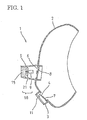
- an exhalation opening 4 and an inhalation opening 6 are formed in a facepiece 2 of a breathing apparatus 1.
- the exhalation opening 4 is covered on the outer surface thereof with an exhalation valve cover 3 provided on the facepiece 2.
- the inhalation opening 6 is covered on the outer surface thereof with a filtration material cover 5 provided on the facepiece 2.
- An exhalation valve 7 which is open during exhalation and closed during inhalation is provided in the exhalation opening 4.
- an inhalation valve 8 which is closed during exhalation and open during inhalation is provided in the inhalation opening 6.
- a filtration material 15 and a blower 16 are disposed opposite each other inside the filtration material cover 5 on the outer side of the inhalation valve 8.
- the blower 16 is composed of an impeller 21 and a motor 9 for rotationally driving the impeller 21.
- the shaft of the impeller 21 is directly connected to the output shaft of the motor 9. If the motor 9 is activated and the impeller 21 is rotated, the outer air passes through the filtration material 15 and is blown inside of the facepiece 2 via the inhalation opening 6.
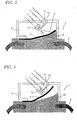
- An exhalation valve seat 10 is mounted on the periphery of the exhalation opening 4 of the facepiece 2, and the exhalation valve 7 is mounted on the exhalation valve seat 10. Further, a sensor composed of the photointerrupter 11 which is sensitive to the movement of the exhalation valve 7 is disposed on the outer side of the exhalation valve 7 in the position close to the exhalation valve 7.
- the photointerrupter 11 comprises a light-emitting diode 12 and a transistor receiver 13.
- the light-emitting surface of the light-emitting diode 12 and the light-receiving surface of the transistor receiver 13 face the exhalation valve 7. If the IR radiation that was output from the light-emitting diode 12 is received by the transistor receiver 13, the photointerrupter 11 generates a signal.
- the exhalation valve 7 comes in tight contact with the exhalation valve seat 10, as shown in FIG. 2.
- the exhalation valve 7 recedes from the photointerrupter 11 at no less than the set distance d. Accordingly, the IR radiation that was output from the light-emitting diode 12 and reflected by the exhalation valve 7 does not fall on the light-receiving surface of the transistor receiver 13 and, therefore, no signal is generated by the photointerrupter 11.
- the exhalation valve 7 recedes from the exhalation valve seat 10 and approaches the photointerrupter 11, as shown in FIG. 3.
- the distance from the exhalation valve to the photointerrupter 11 becomes less than the set distance d.
- the IR radiation that was output from the light-emitting diode 12 and reflected by the exhalation valve 7 falls on the light-receiving surface of the transistor receiver 13.
- the photointerrupter 11 generates a signal.
- a first transistor 17 is connected to a second transistor 18 and the operation of the first transistor is controlled by the second transistor 18.
- the second transistor 18 is connected to the transistor receiver 13 of the photointerrupter 11 via a conductor 19.
- the transistor receiver 13 When the exhalation valve 7 is closed and the IR radiation that was output from the light-receiving diode 12 and reflected by the exhalation valve 7 does not fall on the transistor receiver 13, the transistor receiver 13 generates no output. Therefore, the second transistor 18 is not actuated. For this reason, the operation of the first transistor 17 is not controlled. As a result, because the first transistor 17 operates so as to supply electric power to the motor 9, the motor 9 operates in a usual mode and drives the blower 16, thereby introducing the outside air inside the facepiece 2 through the inhalation opening 6.
- the inner surface of the inhalation opening 6 formed in the facepiece 2 of the breathing apparatus is covered with the inhalation valve cover 20 provided on the facepiece 2.
- the inhalation valve 8 is disposed inside the inhalation valve cover 20. During inhalation, the inhalation valve 8 moves so as to recede from the inhalation opening 6 and introduces the outside air through the inhalation opening 6. During exhalation, the valve moves so as to approach the inhalation opening 6, comes in tight contact with the inhalation opening 6, and closes the inhalation opening 6.
- the photointerrupter 11 is mounted on the surface of the inhalation valve cover 20 which faces the inhalation valve 8.
- the photointerrupter 11 is composed of a light-emitting diode and a transistor receiver, similarly to the first embodiment.
- the inhalation valve 8 If the inhalation valve 8 is open and approaches the surface of the inhalation valve cover 20 where the photointerrupter 11 is located, that is, if the distance between the inhalation valve 8 and photointerrupter 11 becomes close to the prescribed distance d, the IR radiation that was output from the light-emitting diode and reflected by the inhalation valve 8, falls on the transistor receiver. As a consequence, the above-mentioned transistor receiver that has received the IR radiation generates an output which causes the motor 9 to execute normal operation and to drive the blower 16, thereby blowing the air through the inhalation opening 6 into the facepiece 2.
- the inhalation valve 8 is closed, the distance between the inhalation valve 8 and photointerrupter 11 exceeds the preset distance d, and the IR radiation that was output from the light-emitting diode and reflected by the inhalation valve 8 does not fall on the transistor receiver. As a result, the transistor receiver generates no output. As a consequence, blowing of the blower 16 is slowed down or is terminated.
- the transistor receiver when the inhalation valve 8 is open and the distance to the photointerrupter 11 decreases, the transistor receiver receives the IR radiation, whereas when the inhalation valve 8 is closed and the distance to the photointerrupter 11 is increased, the transistor receiver does not receive the IR radiation. Conversely, it is also possible that the transistor receiver receives no IR radiation when the inhalation valve is open and the distance to the photointerrupter 11 is decreased, whereas the transistor receiver receives the IR radiation when the inhalation valve 8 is closed and the distance to the photointerrupter 11 is increased. In such a case, the relationship between the reception of IR radiation by the transistor receiver and control of the motor 9 for driving the blower is identical to that of the first embodiment and the circuit shown in FIG. 4 can be used as is.
- the light-emitting surface of the light-emitting diode and the light-receiving surface of the transistor receiver are disposed opposite each other via a certain clearance, and only when the inhalation valve 8 is closed or only when it is open to a certain degree, at least part of the inhalation valve 8 is introduced between the light-emitting diode and transistor receiver, and the light that was output from the light-emitting diode is shielded and does not reach the transistor receiver.
- the photointerrupter can send a signal corresponding to the position of the inhalation valve 8 to the second transistor 18 (FIG. 4) for driving the motor.
- the photointerrupter 11 was arranged in the position facing the surface of the inhalation valve 8.
- the photointerrupter 11 may be instead arranged around the inhalation valve 8, such an arrangement enabling the photointerrupter 11 to sense the movement of the end surface of the inhalation valve 8.
- Both the exhalation valve 7 and the exhalation valve seat 10 are formed from an electrically conductive material such as an electrically conductive rubber or the like or from an electrically conductive material subjected to processing inducing electric conductivity.
- the exhalation valve seat 10 is mounted on the facepiece of the breathing apparatus upon splitting into at least two parts. A plus pole is formed on one of the two parts of the exhalation valve seat 10 and a minus pole is formed on the other part.
- the exhalation valve seat 10 functions as a sensor sensitive to the movement of the exhalation valve 7.
- the exhalation valve 7 is closed and brought in contact with the exhalation valve seat 10.
- the plus pole and minus pole of the exhalation valve seat 10 are connected to each other via the exhalation valve 7, causing electric current (signal) to flow.
- electric power is supplied to the motor 9, the motor 9 operates in a normal mode, and ventilation is conducted by the blower 16.
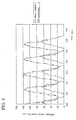
- the increase in the draft resistance of filtration material 15 was studied by using the breathing apparatus 1 in accordance with the present invention and conducting breathing at a rate of 15 times per minute and 0.75 L per inhalation at a dust concentration of 30 mg/m 3 .
- the draft resistance of the filtration material was studied under identical conditions on the conventional breathing apparatus in which ventilation with the blower was also conducted during exhalation. The test results are shown in FIG. 7.
- the conventional breathing apparatus required only 90 minutes to reach a draft resistance of 190 Pa which is a replacement criterion for the filtration material, whereas in the breathing apparatus 1 in accordance with the present invention, this interval was 180 minutes, that is, twice as long.
- test results show that in the conventional breathing apparatus the battery had to be replaced in 75 minutes, whereas in the breathing apparatus 1 in accordance with the present invention, the replacement period was more than 260 minutes, that is, longer by a factor of about 3.5.
- the peak of pressure during exhalation in the facepiece 2 was at 120 Pa in the conventional breathing apparatus and at less than 70 Pa in the breathing apparatus 1 in accordance with the present invention.
- the breathing apparatus 1 in accordance with the present invention reduced the exhalation resistance during exhalation by about 40% relative to that of the conventional breathing apparatus.
- the exhalation valve or inhalation valve which is originally provided in the breathing apparatus, is employed to conduct switching of the blower ventilation linked to breathing, a large number of parts are not necessary and complex air channels are not required. Therefore, the structure can be simple.
Landscapes
- Health & Medical Sciences (AREA)
- Pulmonology (AREA)
- General Health & Medical Sciences (AREA)
- Business, Economics & Management (AREA)
- Emergency Management (AREA)
- Respiratory Apparatuses And Protective Means (AREA)
- Check Valves (AREA)
- Indication Of The Valve Opening Or Closing Status (AREA)
Abstract
Description
Claims (3)
- A breathing apparatus, comprising:wherein power supply to said motor is controlled based on the signals from said sensor.a facepiece with an inhalation opening and an exhalation opening formed therein;an inhalation valve disposed adjacent to said inhalation opening so as to be open during inhalation and closed during exhalation;an exhalation valve disposed adjacent to said exhalation opening so as to be closed during inhalation and open during exhalation;a blower driven by a motor for blowing the outside air into said facepiece through said inhalation opening; anda sensor which is sensitive to the opening or closing operation of said exhalation valve or inhalation valve,
- The breathing apparatus according to claim 1, wherein said sensor comprises a photointerrupter disposed in the vicinity of said exhalation valve or inhalation valve and sensing the position of said exhalation valve or inhalation valve.
- The breathing apparatus according to claim 1, wherein said sensor comprises said exhalation valve or inhalation valve formed from an electrically conductive material and a valve seat formed from an electrically conductive material secured to the facepiece and detects that said exhalation valve or inhalation valve has been closed by sensing the electric current from said exhalation valve or inhalation valve to the valve seat.
Applications Claiming Priority (3)
| Application Number | Priority Date | Filing Date | Title |
|---|---|---|---|
| JP2001198494 | 2001-06-29 | ||
| JP2001198494A JP3726886B2 (en) | 2001-06-29 | 2001-06-29 | Breathing apparatus |
| PCT/JP2002/003484 WO2003002205A1 (en) | 2001-06-29 | 2002-04-08 | Respirator |
Publications (3)
| Publication Number | Publication Date |
|---|---|
| EP1417988A1 true EP1417988A1 (en) | 2004-05-12 |
| EP1417988A4 EP1417988A4 (en) | 2008-05-07 |
| EP1417988B1 EP1417988B1 (en) | 2014-08-20 |
Family
ID=19035936
Family Applications (1)
| Application Number | Title | Priority Date | Filing Date |
|---|---|---|---|
| EP02714530.9A Expired - Lifetime EP1417988B1 (en) | 2001-06-29 | 2002-04-08 | Respirator |
Country Status (8)
| Country | Link |
|---|---|
| US (1) | US7195015B2 (en) |
| EP (1) | EP1417988B1 (en) |
| JP (1) | JP3726886B2 (en) |
| KR (1) | KR100525027B1 (en) |
| CN (1) | CN1276783C (en) |
| AU (1) | AU2002246378B2 (en) |
| CA (1) | CA2452576C (en) |
| WO (1) | WO2003002205A1 (en) |
Cited By (12)
| Publication number | Priority date | Publication date | Assignee | Title |
|---|---|---|---|---|
| WO2015009679A3 (en) * | 2013-07-15 | 2015-03-19 | 3M Innovative Properties Company | Respirator having optically active exhalation valve |
| EP2070563A4 (en) * | 2006-10-04 | 2015-05-06 | Koken Kk | MASK DEVICE WITH BLOWER |
| US9192795B2 (en) | 2011-10-07 | 2015-11-24 | Honeywell International Inc. | System and method of calibration in a powered air purifying respirator |
| WO2017098329A1 (en) * | 2015-12-07 | 2017-06-15 | Christopher Dobbing | Respirator mask management system |
| US9808656B2 (en) | 2012-01-09 | 2017-11-07 | Honeywell International Inc. | System and method of oxygen deficiency warning in a powered air purifying respirator |
| DE102016218659A1 (en) | 2016-09-28 | 2018-03-29 | Ford Global Technologies, Llc | check valve |
| EP3406301A1 (en) * | 2017-05-22 | 2018-11-28 | Koninklijke Philips N.V. | A mask-based breathing apparatus and control method |
| US10493974B2 (en) | 2016-09-28 | 2019-12-03 | Ford Global Technologies, Llc | Method for diagnosing fault in a vacuum system including a check valve |
| US11813581B2 (en) | 2017-07-14 | 2023-11-14 | 3M Innovative Properties Company | Method and adapter for conveying plural liquid streams |
| US11877604B2 (en) | 2007-05-03 | 2024-01-23 | 3M Innovative Properties Company | Maintenance-free respirator that has concave portions on opposing sides of mask top section |
| US11904191B2 (en) | 2007-05-03 | 2024-02-20 | 3M Innovative Properties Company | Anti-fog respirator |
| US12616258B2 (en) | 2014-12-04 | 2026-05-05 | 3M Innovative Properties Company | Respirator tab |
Families Citing this family (48)
| Publication number | Priority date | Publication date | Assignee | Title |
|---|---|---|---|---|
| US7188622B2 (en) * | 2003-06-19 | 2007-03-13 | 3M Innovative Properties Company | Filtering face mask that has a resilient seal surface in its exhalation valve |
| FR2856930B1 (en) * | 2003-07-04 | 2007-09-07 | Saime Sarl | MODULAR TURBINE BREATHING AIDING DEVICE. |
| GB2404866B (en) | 2003-08-15 | 2008-02-27 | Shahar Hayek | Respiratory apparatus |
| CN101816814B (en) * | 2003-09-25 | 2012-11-07 | 雷斯梅德有限公司 | Ventilator mask and system |
| US8584676B2 (en) * | 2003-11-19 | 2013-11-19 | Immediate Response Technologies | Breath responsive filter blower respirator system |
| SA05260065B1 (en) | 2004-03-26 | 2009-12-29 | سينجنتا بارتيسيبيشنزا ايه جى | A Herbicidal Combination |
| JP4969796B2 (en) * | 2005-05-24 | 2012-07-04 | ゆり 山口 | Breathing pattern improvement device by inhalation synchronized scent stimulation |
| US20070000493A1 (en) * | 2005-06-01 | 2007-01-04 | Cox Kingsley J | Apparatus for maintaining airway patency |
| JP4708313B2 (en) * | 2006-11-14 | 2011-06-22 | 興研株式会社 | Breath-linked blower mask system |
| JP4931626B2 (en) * | 2007-02-08 | 2012-05-16 | 興研株式会社 | Breath-linked blower mask system |
| KR100828132B1 (en) | 2007-04-25 | 2008-05-08 | 김경진 | Anti-vibration device for exercise with minimal respiratory resistance |
| JP2008289600A (en) * | 2007-05-23 | 2008-12-04 | Koken Ltd | Breath-linked blower mask device |
| JP2008295922A (en) * | 2007-06-04 | 2008-12-11 | Shigematsu Works Co Ltd | Respiratory protection device with electric fan by use of hole element |
| JP5041596B2 (en) | 2007-12-07 | 2012-10-03 | 株式会社重松製作所 | Breathing apparatus |
| FR2931643B1 (en) * | 2008-06-03 | 2011-10-14 | Dior Christian Parfums | MASCARA BRUSH COMPONENT, MASCARA BRUSH, AND MASCARA APPLICATION ASSEMBLY |
| JP2010012280A (en) * | 2009-09-02 | 2010-01-21 | Koken Ltd | Mask device with blower |
| BR112012011337A2 (en) * | 2009-10-20 | 2019-09-24 | Deshum Medical Llc | "integrated positive airway pressure apparatus" |
| EP2368592B1 (en) * | 2010-03-26 | 2013-04-24 | Dräger Medical GmbH | Combi-valve for a blower driven ventilator |
| CN102284149B (en) * | 2010-06-18 | 2013-03-20 | 中国人民解放军总参谋部工程兵科研三所 | Breath-synchronized powered air supply type breathing mask |
| SE534951C2 (en) * | 2010-06-18 | 2012-02-28 | Facecover Sweden Ab | Motor-driven Air Purifying Respirator (PAPR) |
| US9084859B2 (en) | 2011-03-14 | 2015-07-21 | Sleepnea Llc | Energy-harvesting respiratory method and device |
| CN102793312B (en) * | 2012-08-13 | 2016-01-20 | 北京华创矿安科技有限公司 | There is the anti-dust respirator that dynamic property is breathed |
| USD746974S1 (en) | 2013-07-15 | 2016-01-05 | 3M Innovative Properties Company | Exhalation valve flap |
| KR101505648B1 (en) * | 2013-10-29 | 2015-03-24 | 유태곤 | Nose mask |
| CN103751919B (en) * | 2014-01-27 | 2016-05-11 | 胡昀 | Can form with face the mouth mask of airtight respiratory cavity |
| KR101733470B1 (en) | 2015-05-06 | 2017-05-25 | 주식회사 아이카이스트 | Pressure sensor-based electric respiratory system with real-time breath control function |
| GB201508114D0 (en) | 2015-05-12 | 2015-06-24 | 3M Innovative Properties Co | Respirator tab |
| US10342999B2 (en) * | 2015-10-16 | 2019-07-09 | Yang Song | Particulate filter face mask having fan breathing assist |
| CN105476116B (en) * | 2016-01-18 | 2018-05-15 | 北京华创矿安科技有限公司 | A kind of power spray mask with sensor |
| WO2017147109A1 (en) | 2016-02-24 | 2017-08-31 | Colborn John C | Low pressure surface supplied air system and method |
| CN105935473A (en) * | 2016-06-28 | 2016-09-14 | 中山市赛夫特劳保用品有限公司 | Auxiliary air supply gas mask connector |
| CN106820346A (en) * | 2017-03-10 | 2017-06-13 | 马文清 | Aid in into outlet haze mouth mask |
| CN106730227A (en) * | 2017-03-15 | 2017-05-31 | 徐州医科大学附属医院 | Anaesthetic mask with exhaust-gas treatment function |
| KR20190025467A (en) * | 2017-09-01 | 2019-03-11 | 쓰리엠 이노베이티브 프로퍼티즈 캄파니 | Respirator |
| US11541974B2 (en) | 2017-12-01 | 2023-01-03 | Setaysha Technical Solutions, Llc | Low pressure respiration gas delivery method |
| US20210162153A1 (en) * | 2017-12-06 | 2021-06-03 | The Regents Of The University Of California | Systems And Methods For Monitoring Tracheotomy Patients |
| CN108371361A (en) * | 2018-01-08 | 2018-08-07 | 赵辉 | A kind of mask and its method of ventilation |
| CN108201665B (en) * | 2018-02-24 | 2022-11-18 | 荆州思创科技开发有限公司 | Protective mask with detection device |
| JP7411948B2 (en) * | 2018-03-30 | 2024-01-12 | 公立大学法人公立諏訪東京理科大学 | Clothes, heat stroke prevention system and hydration warning system |
| WO2020129006A1 (en) | 2018-12-21 | 2020-06-25 | 3M Innovative Properties Company | Systems and methods for automated respirator |
| WO2020129017A2 (en) | 2018-12-21 | 2020-06-25 | 3M Innovative Properties Company | Systems and methods for automated respirator |
| KR102079726B1 (en) * | 2019-07-26 | 2020-02-19 | 현한울 | Adhering mask |
| CN111165937A (en) * | 2020-01-27 | 2020-05-19 | 梅雪竹 | Local extruded disinfection formula gauze mask of different facial recesses of adaptation |
| KR102151670B1 (en) * | 2020-03-26 | 2020-09-03 | 김형준 | Air valve for Mask |
| JP7515044B2 (en) * | 2020-10-22 | 2024-07-12 | 特定非営利活動法人e自警ネットワーク研究会 | Method and management system for managing mask wearing status and contact with others |
| US12473900B2 (en) | 2021-06-07 | 2025-11-18 | Setaysha Technical Solutions LLC | High volume, low pressure oilless pump |
| JP7764596B2 (en) * | 2021-10-20 | 2025-11-05 | 深▲ジェン▼引望智能技術有限公司 | Valves and Electronic Devices |
| CN116251265B (en) * | 2023-03-17 | 2026-04-28 | 深圳市康冠医疗设备有限公司 | Atomizer |
Family Cites Families (17)
| Publication number | Priority date | Publication date | Assignee | Title |
|---|---|---|---|---|
| US4430995A (en) * | 1981-05-29 | 1984-02-14 | Hilton Joseph R | Power assisted air-purifying respirators |
| GB8315589D0 (en) * | 1983-06-07 | 1983-07-13 | Racal Safety Ltd | Breathing apparatus |
| DE3471008D1 (en) | 1983-06-07 | 1988-06-16 | Racal Safety Ltd | Improvements in and relating to breathing apparatus |
| GB8721040D0 (en) * | 1987-09-08 | 1987-10-14 | Chapman & Smith Ltd | Respirators |
| GB2215615B (en) * | 1988-03-21 | 1991-12-18 | Sabre Safety Ltd | Breathing apparatus |
| EP0352938B1 (en) * | 1988-07-26 | 1993-10-06 | RACAL HEALTH & SAFETY LIMITED | Breathing apparatus |
| DE3843486A1 (en) * | 1988-12-23 | 1990-06-28 | Draegerwerk Ag | BREATHING DEVICE WITH FAN SUPPORT AND REGENERATION OF THE BREATHING FILTER |
| US4899740A (en) * | 1989-01-17 | 1990-02-13 | E. D. Bullard Company | Respirator system for use with a hood or face mask |
| FR2680467B1 (en) * | 1991-08-21 | 1997-04-04 | Intertechnique Sa | RESPIRATORY PROTECTION EQUIPMENT AGAINST POLLUTANTS. |
| DE4132680C2 (en) * | 1991-10-01 | 1994-02-10 | Draegerwerk Ag | Respirator mask with inner half mask and pollutant indicator |
| DE4202025C2 (en) * | 1992-01-25 | 1995-02-02 | Draegerwerk Ag | Fan-assisted breathing apparatus with adjustable fan performance |
| DE4207533C2 (en) * | 1992-03-10 | 1994-03-31 | Draegerwerk Ag | Respirator with breathing air return |
| GB9307733D0 (en) * | 1993-04-14 | 1993-06-02 | Msa Britain Ltd | Respiratory protective device |
| US5906203A (en) * | 1994-08-01 | 1999-05-25 | Safety Equipment Sweden Ab | Breathing apparatus |
| AUPN191095A0 (en) * | 1995-03-23 | 1995-04-27 | Safety Equipment Australia Pty Ltd | Positive air-purifying respirator management system |
| JPH10118183A (en) * | 1996-10-21 | 1998-05-12 | Nobel Igaku Kenkyusho:Kk | Nose covering |
| US6135106A (en) * | 1997-08-22 | 2000-10-24 | Nellcor Puritan-Bennett, Inc. | CPAP pressure and flow transducer |
-
2001
- 2001-06-29 JP JP2001198494A patent/JP3726886B2/en not_active Expired - Lifetime
-
2002
- 2002-04-08 WO PCT/JP2002/003484 patent/WO2003002205A1/en not_active Ceased
- 2002-04-08 AU AU2002246378A patent/AU2002246378B2/en not_active Ceased
- 2002-04-08 US US10/482,272 patent/US7195015B2/en not_active Expired - Fee Related
- 2002-04-08 CA CA2452576A patent/CA2452576C/en not_active Expired - Fee Related
- 2002-04-08 EP EP02714530.9A patent/EP1417988B1/en not_active Expired - Lifetime
- 2002-04-08 KR KR10-2003-7002811A patent/KR100525027B1/en not_active Expired - Fee Related
- 2002-04-08 CN CNB02802205XA patent/CN1276783C/en not_active Expired - Fee Related
Cited By (20)
| Publication number | Priority date | Publication date | Assignee | Title |
|---|---|---|---|---|
| EP2070563A4 (en) * | 2006-10-04 | 2015-05-06 | Koken Kk | MASK DEVICE WITH BLOWER |
| US11877604B2 (en) | 2007-05-03 | 2024-01-23 | 3M Innovative Properties Company | Maintenance-free respirator that has concave portions on opposing sides of mask top section |
| US11904191B2 (en) | 2007-05-03 | 2024-02-20 | 3M Innovative Properties Company | Anti-fog respirator |
| US9192795B2 (en) | 2011-10-07 | 2015-11-24 | Honeywell International Inc. | System and method of calibration in a powered air purifying respirator |
| US9808656B2 (en) | 2012-01-09 | 2017-11-07 | Honeywell International Inc. | System and method of oxygen deficiency warning in a powered air purifying respirator |
| JP2016525174A (en) * | 2013-07-15 | 2016-08-22 | スリーエム イノベイティブ プロパティズ カンパニー | Respirator with optically active exhalation valve |
| WO2015009679A3 (en) * | 2013-07-15 | 2015-03-19 | 3M Innovative Properties Company | Respirator having optically active exhalation valve |
| RU2642340C2 (en) * | 2013-07-15 | 2018-01-24 | 3М Инновейтив Пропертиз Компани | Respirator with optically active exhalation valve |
| US12005277B2 (en) | 2013-07-15 | 2024-06-11 | 3M Innovative Properties Company | Respirator having optically active exhalation valve |
| AU2014290207B2 (en) * | 2013-07-15 | 2017-05-11 | 3M Innovative Properties Company | Respirator having optically active exhalation valve |
| EP4272840A1 (en) * | 2013-07-15 | 2023-11-08 | 3M Innovative Properties Co. | Respirator having optically active exhalation valve |
| US10905903B2 (en) | 2013-07-15 | 2021-02-02 | 3M Innovative Properties Company | Respirator having optically active exhalation valve |
| US12616258B2 (en) | 2014-12-04 | 2026-05-05 | 3M Innovative Properties Company | Respirator tab |
| WO2017098329A1 (en) * | 2015-12-07 | 2017-06-15 | Christopher Dobbing | Respirator mask management system |
| US10493974B2 (en) | 2016-09-28 | 2019-12-03 | Ford Global Technologies, Llc | Method for diagnosing fault in a vacuum system including a check valve |
| DE102016218659B4 (en) | 2016-09-28 | 2025-02-20 | Ford Global Technologies, Llc | check valve |
| DE102016218659A1 (en) | 2016-09-28 | 2018-03-29 | Ford Global Technologies, Llc | check valve |
| WO2018215441A1 (en) * | 2017-05-22 | 2018-11-29 | Koninklijke Philips N.V. | A mask-based breathing apparatus and control method |
| EP3406301A1 (en) * | 2017-05-22 | 2018-11-28 | Koninklijke Philips N.V. | A mask-based breathing apparatus and control method |
| US11813581B2 (en) | 2017-07-14 | 2023-11-14 | 3M Innovative Properties Company | Method and adapter for conveying plural liquid streams |
Also Published As
| Publication number | Publication date |
|---|---|
| KR20030096215A (en) | 2003-12-24 |
| CN1464793A (en) | 2003-12-31 |
| AU2002246378B2 (en) | 2006-08-03 |
| JP2003010349A (en) | 2003-01-14 |
| CN1276783C (en) | 2006-09-27 |
| WO2003002205A1 (en) | 2003-01-09 |
| CA2452576C (en) | 2011-01-18 |
| KR100525027B1 (en) | 2005-10-31 |
| EP1417988A4 (en) | 2008-05-07 |
| US7195015B2 (en) | 2007-03-27 |
| JP3726886B2 (en) | 2005-12-14 |
| EP1417988B1 (en) | 2014-08-20 |
| CA2452576A1 (en) | 2003-01-09 |
| US20040168689A1 (en) | 2004-09-02 |
Similar Documents
| Publication | Publication Date | Title |
|---|---|---|
| EP1417988B1 (en) | Respirator | |
| CA1310248C (en) | Breathing apparatus | |
| US8584676B2 (en) | Breath responsive filter blower respirator system | |
| EP2070563B1 (en) | Mask device with blower | |
| US4886056A (en) | Breathing apparatus | |
| US4590951A (en) | Breathing apparatus | |
| EP2486959B1 (en) | Respiratory device | |
| US5018518A (en) | Gas work with sensing and alarm means | |
| JP2008289600A (en) | Breath-linked blower mask device | |
| JP4931626B2 (en) | Breath-linked blower mask system | |
| CN118949306A (en) | Intelligent breathing follow-up electric air supply mask and method | |
| HK1065497A (en) | Respirator | |
| JP3780455B2 (en) | Mask device with blower | |
| JP3682420B2 (en) | Breathing apparatus | |
| SE447792B (en) | DEVICE FOR SAFETY MASK | |
| CN117180655A (en) | A breathing follow-up gas mask air supply device and air supply control method |
Legal Events
| Date | Code | Title | Description |
|---|---|---|---|
| PUAI | Public reference made under article 153(3) epc to a published international application that has entered the european phase |
Free format text: ORIGINAL CODE: 0009012 |
|
| 17P | Request for examination filed |
Effective date: 20040105 |
|
| AK | Designated contracting states |
Kind code of ref document: A1 Designated state(s): AT BE CH CY DE DK ES FI FR GB GR IE IT LI LU MC NL PT SE TR |
|
| REG | Reference to a national code |
Ref country code: HK Ref legal event code: DE Ref document number: 1065497 Country of ref document: HK |
|
| A4 | Supplementary search report drawn up and despatched |
Effective date: 20080404 |
|
| 17Q | First examination report despatched |
Effective date: 20090202 |
|
| REG | Reference to a national code |
Ref country code: HK Ref legal event code: WD Ref document number: 1065497 Country of ref document: HK |
|
| REG | Reference to a national code |
Ref country code: DE Ref legal event code: R079 Ref document number: 60246551 Country of ref document: DE Free format text: PREVIOUS MAIN CLASS: A62B0009000000 Ipc: A62B0018000000 |
|
| GRAP | Despatch of communication of intention to grant a patent |
Free format text: ORIGINAL CODE: EPIDOSNIGR1 |
|
| RIC1 | Information provided on ipc code assigned before grant |
Ipc: A62B 18/10 20060101ALI20140213BHEP Ipc: A62B 18/00 20060101AFI20140213BHEP |
|
| INTG | Intention to grant announced |
Effective date: 20140227 |
|
| RAP1 | Party data changed (applicant data changed or rights of an application transferred) |
Owner name: KOKEN LTD. |
|
| GRAS | Grant fee paid |
Free format text: ORIGINAL CODE: EPIDOSNIGR3 |
|
| GRAA | (expected) grant |
Free format text: ORIGINAL CODE: 0009210 |
|
| AK | Designated contracting states |
Kind code of ref document: B1 Designated state(s): CH DE FR GB IT LI SE |
|
| REG | Reference to a national code |
Ref country code: GB Ref legal event code: FG4D |
|
| REG | Reference to a national code |
Ref country code: CH Ref legal event code: EP |
|
| REG | Reference to a national code |
Ref country code: DE Ref legal event code: R096 Ref document number: 60246551 Country of ref document: DE Effective date: 20140925 |
|
| REG | Reference to a national code |
Ref country code: SE Ref legal event code: TRGR |
|
| REG | Reference to a national code |
Ref country code: DE Ref legal event code: R097 Ref document number: 60246551 Country of ref document: DE |
|
| PLBE | No opposition filed within time limit |
Free format text: ORIGINAL CODE: 0009261 |
|
| STAA | Information on the status of an ep patent application or granted ep patent |
Free format text: STATUS: NO OPPOSITION FILED WITHIN TIME LIMIT |
|
| 26N | No opposition filed |
Effective date: 20150521 |
|
| REG | Reference to a national code |
Ref country code: CH Ref legal event code: PL |
|
| PG25 | Lapsed in a contracting state [announced via postgrant information from national office to epo] |
Ref country code: CH Free format text: LAPSE BECAUSE OF NON-PAYMENT OF DUE FEES Effective date: 20150430 Ref country code: LI Free format text: LAPSE BECAUSE OF NON-PAYMENT OF DUE FEES Effective date: 20150430 |
|
| REG | Reference to a national code |
Ref country code: FR Ref legal event code: PLFP Year of fee payment: 15 |
|
| PGFP | Annual fee paid to national office [announced via postgrant information from national office to epo] |
Ref country code: DE Payment date: 20160405 Year of fee payment: 15 Ref country code: GB Payment date: 20160406 Year of fee payment: 15 |
|
| PGFP | Annual fee paid to national office [announced via postgrant information from national office to epo] |
Ref country code: IT Payment date: 20160418 Year of fee payment: 15 Ref country code: SE Payment date: 20160412 Year of fee payment: 15 |
|
| REG | Reference to a national code |
Ref country code: FR Ref legal event code: PLFP Year of fee payment: 16 |
|
| PGFP | Annual fee paid to national office [announced via postgrant information from national office to epo] |
Ref country code: FR Payment date: 20170313 Year of fee payment: 16 |
|
| REG | Reference to a national code |
Ref country code: DE Ref legal event code: R119 Ref document number: 60246551 Country of ref document: DE |
|
| GBPC | Gb: european patent ceased through non-payment of renewal fee |
Effective date: 20170408 |
|
| PG25 | Lapsed in a contracting state [announced via postgrant information from national office to epo] |
Ref country code: DE Free format text: LAPSE BECAUSE OF NON-PAYMENT OF DUE FEES Effective date: 20171103 |
|
| PG25 | Lapsed in a contracting state [announced via postgrant information from national office to epo] |
Ref country code: SE Free format text: LAPSE BECAUSE OF NON-PAYMENT OF DUE FEES Effective date: 20170409 Ref country code: GB Free format text: LAPSE BECAUSE OF NON-PAYMENT OF DUE FEES Effective date: 20170408 |
|
| PG25 | Lapsed in a contracting state [announced via postgrant information from national office to epo] |
Ref country code: IT Free format text: LAPSE BECAUSE OF NON-PAYMENT OF DUE FEES Effective date: 20170408 |
|
| PG25 | Lapsed in a contracting state [announced via postgrant information from national office to epo] |
Ref country code: FR Free format text: LAPSE BECAUSE OF NON-PAYMENT OF DUE FEES Effective date: 20180430 |