EP1416507A1 - Disjoncteur comprenant un ensemble de commande et une chambre de coupure, son procédé d'assemblage et organe auxiliaire pour cet assemblage - Google Patents
Disjoncteur comprenant un ensemble de commande et une chambre de coupure, son procédé d'assemblage et organe auxiliaire pour cet assemblage Download PDFInfo
- Publication number
- EP1416507A1 EP1416507A1 EP03356168A EP03356168A EP1416507A1 EP 1416507 A1 EP1416507 A1 EP 1416507A1 EP 03356168 A EP03356168 A EP 03356168A EP 03356168 A EP03356168 A EP 03356168A EP 1416507 A1 EP1416507 A1 EP 1416507A1
- Authority
- EP
- European Patent Office
- Prior art keywords
- shaft
- circuit breaker
- elements
- auxiliary member
- crown
- Prior art date
- Legal status (The legal status is an assumption and is not a legal conclusion. Google has not performed a legal analysis and makes no representation as to the accuracy of the status listed.)
- Granted
Links
Images

Classifications
-
- H—ELECTRICITY
- H01—ELECTRIC ELEMENTS
- H01H—ELECTRIC SWITCHES; RELAYS; SELECTORS; EMERGENCY PROTECTIVE DEVICES
- H01H33/00—High-tension or heavy-current switches with arc-extinguishing or arc-preventing means
- H01H33/02—Details
- H01H33/42—Driving mechanisms
-
- F—MECHANICAL ENGINEERING; LIGHTING; HEATING; WEAPONS; BLASTING
- F16—ENGINEERING ELEMENTS AND UNITS; GENERAL MEASURES FOR PRODUCING AND MAINTAINING EFFECTIVE FUNCTIONING OF MACHINES OR INSTALLATIONS; THERMAL INSULATION IN GENERAL
- F16D—COUPLINGS FOR TRANSMITTING ROTATION; CLUTCHES; BRAKES
- F16D1/00—Couplings for rigidly connecting two coaxial shafts or other movable machine elements
- F16D1/12—Couplings for rigidly connecting two coaxial shafts or other movable machine elements allowing adjustment of the parts about the axis
Definitions
- the present invention relates to a circuit breaker comprising a control unit and a breaking, a method of assembling this circuit breaker, as well an auxiliary member allowing this assembly.
- such a circuit breaker comprises a control assembly which is associated with a cut.
- This room contains a pair of contacts arc, at least one of which is movable under the action of the control assembly.
- This mobile contact can thus be moved between two separate positions, corresponding respectively at the opening and closing of the breaker.
- the aforementioned control assembly is able to store mechanical energy, in particular thanks to the presence of springs. It is also provided with a control shaft serrated, which can be rotated during the release of mechanical energy stored in the control assembly.
- the breaking chamber is provided with another shaft of serrated control, the rotation of which moves the movable contact between the two aforementioned positions. It is finally provided a set of synchronization between these two control trees, which is made in the form of a deformable parallelogram.
- this synchronization set first includes two levers, each of which is provided a crown capable of cooperating with a serrated shaft corresponding.
- the opposite ends of these levers are also mutually connected by means of rods, articulated on these levers.
- the operator When he wishes to assemble the circuit breaker described above, the operator has a set of controls, including the serrated shaft is in a given position, so than a switching chamber, whose control shaft is also found in a given position. From these positions he then has to adapt the set of synchronization, in particular by making the two crowns with the two serrated trees above.
- the invention proposes to carry out a circuit breaker to overcome the drawbacks mentioned above.
- the invention aims to propose such a circuit breaker, whose synchronization set has games reduced, in service, while having flexibility satisfactory, particularly with regard to its assembly and disassembly.
- a circuit breaker comprising a control assembly which comprises a first serrated control shaft, or motor shaft, this circuit breaker also comprising a breaking chamber which comprises at least one movable arcing contact, as well as a second serrated control shaft, or follower shaft, capable of moving the movable contact between open and closed positions, this circuit breaker finally comprising a set of synchronization of these shafts, respectively motor and follower, which comprises two levers, each of which is provided with a serrated crown capable of cooperating with a corresponding shaft, as well as two connecting rods, each of which is articulated at its two ends on said levers, characterized in that one of said serrated rings has a number of meshing elements which is different from the number of meshing elements of the serrated shaft with which it cooperates, and in that a connecting member is interposed between this crown and this shaft, this connecting member having internal meshing elements able to cooperate with the meshing elements of the motor shaft, as well as external meshing elements able to cooperate with the elements
- the invention finally relates to an auxiliary organ for the implementation of the assembly process such as defined above, this hollow auxiliary member having meshing elements arranged on its periphery interior, as well as radial marks, distributed regularly, which are provided in a number identical to that of these interior meshing elements.
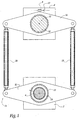
- the circuit breaker illustrated in Figure 1 includes a control unit, shown schematically under form of a block 2.
- This control assembly 2 which is known manner capable of storing mechanical energy, in particular thanks to the presence of springs not shown, is provided with a serrated control shaft 4.
- the term serrated means that the mechanical organ in question is provided mesh elements, which can in particular be teeth or grooves.
- mesh elements can in particular be teeth or grooves.
- the circuit breaker also includes a cut, which is also represented schematic, in the form of a block 6.
- This break 6 has, in a conventional manner, contacts fixed 8 and mobile 10 respectively, both illustrated with also schematically.
- Trees 4 and 12 are connected to each other by through a synchronization assembly, designated as a whole by reference 14.
- This set 14 firstly comprises a first lever 16, in which a serrated crown is formed central 18, intended to cooperate directly with the tree 12.
- a serrated crown is formed central 18, intended to cooperate directly with the tree 12.
- this tree 12 and this crown 18 have the same number of splines.
- the synchronization assembly 14 also includes a second lever 20, the same length as the first lever 16, in which a central serrated crown is hollowed out 22. This cooperates indirectly with the shaft 4, in this sense that their mutual engagement is ensured by through a liaison body plus particularly visible in Figure 2.
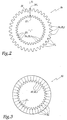
- This connecting member 24 which is hollow, has internal grooves 24 1 capable of cooperating with the external grooves 4 1 of the shaft 4, as well as external grooves 24 2 capable of cooperating with the internal grooves 22 1 of the crown 22. These grooves 4 1 and 22 1 are visible in FIG. 4A.
- N 1 the number of splines 4 1 and 24 1 , present respectively on the shaft 4 and inside the connecting member 24, as well as N 2 the number of splines 24 2 and 22 1 , provided respectively outside the connecting member 24 and on the crown 22.
- N 1 and N 2 are different, that they are advantageously prime numbers between them, in particular that the absolute value of their difference is equal to 1.
- N 1 is equal to 36, while N 2 is equal to 35.
- a visual marker 26 produced by any suitable means, extends along this axis A.
- the function of this reference 26, which is here a radial line, will be explained in the following.
- the synchronization assembly 14 comprises two connecting rods 28 (Figure 1), of the same length, each of which connects two ends opposite levers 16 and 20. It is note that these levers 16 and 20 thus form a deformable parallelogram with these connecting rods 28.
- a control signal is sent, in a manner known as such, to the control assembly 2.
- the latter then releases the accumulated energy, so rotating the control shaft 4, which is says engine.
- This motor shaft 4 then drives, via the assembly of synchronization 14, the rotation of the chamber shaft break 12, says follower. The latter then initiates the displacement of the movable contact 10 relative to the contact fixed 8, so as to place the circuit breaker in its position desired.
- the grooves of one of the control shafts 4 or 12 may not be located opposite the recesses of the corresponding toothed crown 22 or 18, which prevents their mutual cooperation.
- the only economically viable solution then consists in rotating the follower shaft 12, at a consequent angle of up to 5 °, or 180 ° / N 1 , which modifies the position of the movable contact 10 in an unacceptable manner.
- this connecting member 24 there is a certain angular position of this connecting member 24, allowing it to be inserted optimally in this intermediate space 29.
- This optimal angular orientation corresponds to cooperation between, on the one hand, the splines 4 1 of the shaft 4 and the inner splines 24 1 of the member 24 as well as, on the other hand, between the splines 22 1 of the crown 22 and the outer splines 24 2 of the member 24.
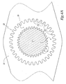
- This auxiliary member which is hollow, is generally designated by the reference 30. It is provided with internal grooves 30 1 , the number and pitch of which are identical to those 24 1 of the connecting member.
- the auxiliary member 30 is smooth, namely that it is devoid of grooves. Its outer diameter corresponds substantially to that of the connecting member 24, taken at the base of the outer grooves 24 2 .
- radial lines 32 are formed on the body of the auxiliary member 30. These lines 32, the number N 1 of which corresponds to that of the grooves 30 1 , pass through the centers of the different hollows 31 1 , located between two grooves 30 1 adjacent.
- the aim is to identify the line 32 ′ which is best centered, at its outer radial end, with respect to a corresponding recess 23 1 of the crown 22.
- This recess says optimal, assigned the reference 23 ′ 1 , is identified by means of a reference 26 ′, provided by the operator facing the crown.
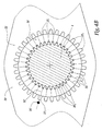
- the outer grooves 24 2 of this connecting member are optimally centered on the recesses 23 1 formed at the inner periphery of the ring 22.
- the reference 26 is coincident, in FIG. 4C, with the line 32 'of FIG. 4B, which we have seen has an optimal centering, with respect to the recess 23' 1 .
- the “optimal” line 132 ′ has an angular offset, assigned to the reference ⁇ , relative to the median axis A 2 of the recess 123 ′ 1 .
- this angle ⁇ can be determined from the number of splines N 1 and N 2 .
- this maximum value is equal, expressed in degrees, to 180 * ABS ((N 2 - N 1 ) / (N 1 * N 2 )), where ABS corresponds to the absolute value of the number expressed in parentheses.
- the different lines 32, formed on the auxiliary member 30, not to be aligned with the median axis of each recess 31 1 , but for example with the median axis of each groove 30 1 .
- the mark 26 then extends between an inner groove and an outer recess of the connecting member.
- each benchmark can be practiced other than radially, especially so angular.
Landscapes
- Engineering & Computer Science (AREA)
- General Engineering & Computer Science (AREA)
- Mechanical Engineering (AREA)
- Driving Mechanisms And Operating Circuits Of Arc-Extinguishing High-Tension Switches (AREA)
- Steering Controls (AREA)
Abstract
Description
caractérisé en ce que l'une desdites couronnes dentelées possède un nombre d'éléments d'engrènement qui est différent du nombre d'éléments d'engrènement de l'arbre dentelé avec lequel elle coopère, et en ce qu'un organe de liaison est intercalé entre cette couronne et cet arbre, cet organe de liaison possédant des éléments d'engrènement intérieurs aptes à coopérer avec les éléments d'engrènement de l'arbre moteur, ainsi que des éléments d'engrènement extérieurs aptes à coopérer avec les éléments d'engrènement de ladite couronne dentelée.
- le nombre d'éléments d'engrènement de ladite couronne dentelée et le nombre d'éléments d'engrènement de l'arbre de commande sont des nombres premiers entre eux ;
- la valeur absolue de la différence entre, d'une part, le nombre d'éléments d'engrènement de l'arbre de commande et, d'autre part, le nombre d'éléments d'engrènement de ladite couronne dentelée est égale à 1 ;
- le plus petit des nombres d'éléments d'engrènement de l'arbre de commande et d'éléments d'engrènement de la couronne dentelée est supérieur à douze, de préférence à vingt-six ;
- l'arbre de commande possède trente-six éléments d'engrènement, alors que la couronne dentée possède trente-cinq éléments d'engrènement ;
- l'organe de liaison est marqué d'un repère d'identification s'étendant radialement et/ou angulairement ;
- le repère d'identification s'étend entre un renfoncement intérieur et un élément d'engrènement extérieur, tous deux alignés, de l'organe de liaison ;
- le repère d'identification se trouve radialement en regard d'un autre repère, ménagé sur la couronne dentelée et/ou sur l'arbre de commande ;
- l'autre couronne dentelée possède le même nombre d'éléments d'engrènement que l'arbre de commande sur laquelle elle est montée, de manière à coopérer directement avec cet arbre de commande.
- on monte l'autre couronne dentelée sur son arbre;
- on dispose la périphérie intérieure de la couronne dentelée au voisinage de la périphérie extérieure de son arbre de commande, de sorte que ces périphéries respectivement intérieure et extérieure forment un espace intercalaire ; et
- on introduit l'organe de liaison dans cet espace intercalaire, de manière à le faire coopérer à la fois avec l'arbre de commande et avec la première couronne dentelée.
- avant d'introduire l'organe de liaison dans l'espace intercalaire :
- on utilise un organe auxiliaire creux, possédant des éléments d'engrènement intérieurs identiques aux éléments d'engrènement intérieurs de l'organe de liaison, cet organe auxiliaire possédant une périphérie extérieure telle qu'il peut être introduit dans l'espace intercalaire, sans interférer avec la couronne dentelée, cet organe auxiliaire étant pourvu de marques radiales, reparties régulièrement, qui sont prévues en un nombre identique à celui desdits éléments d'engrènement intérieurs de l'organe auxiliaire,
- on introduit cet organe auxiliaire dans l'espace intercalaire,
- on identifie l'une, dite optimale, desdites marques radiales correspondant à une position de libre introduction de l'organe de liaison dans l'espace intercalaire,
- on réalise, sur ladite couronne dentelée et/ou l'arbre, ledit autre repère correspondant à cette position de libre introduction,
- on enlève cet organe auxiliaire hors de l'espace intercalaire, et
- on introduit l'organe de liaison dans cet espace intercalaire, dans ladite position d'introduction optimale ;
- Lors de l'introduction de l'organe de liaison dans l'espace intercalaire, on aligne le repère d'identification de l'organe de liaison avec ledit autre repère de la couronne dentelée et/ou de l'arbre,
- Chaque marque radiale de l'organe auxiliaire s'étend à partir d'un renfoncement intérieur de cet organe auxiliaire, ménagé entre deux éléments d'engrènement adjacents.
- On identifie la marque radiale optimale, qui se trouve centrée de façon optimale par rapport à un renfoncement, en regard, de la couronne dentelée, et/ou par rapport à un élément d'engrènement, en regard, de l'arbre.
- chaque marque radiale s'étend à partir d'un renfoncement ménagé entre deux éléments d'engrènement intérieurs,
- l'organe auxiliaire possède une périphérie extérieure lisse, notamment cylindrique de section circulaire.
- la figure 1 est une vue schématique, illustrant un disjoncteur conforme à l'invention ;
- la figure 2 est une vue de face, illustrant un organe de liaison, appartenant à l'ensemble de synchronisation dont est pourvu le disjoncteur de la figure 1 ;
- la figure 3 est une vue de face, analogue à la figure 2, illustrant un organe auxiliaire intervenant dans l'assemblage du disjoncteur de la figure 1 ;
- les figures 4A à 4C sont des vues de face, illustrant différentes étapes du montage du disjoncteur de la figure 1 ; et
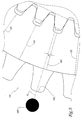
- la figure 5 est une vue de face, à plus grande échelle, illustrant une configuration différente du disjoncteur, lors de son montage.
Claims (17)
- Disjoncteur comprenant un ensemble de commande (2) qui comporte un premier arbre de commande dentelé (4), ou arbre moteur, ce disjoncteur comprenant également une chambre de coupure (6) qui comporte au moins un contact d'arc mobile (10), ainsi qu'un second arbre de commande dentelé (12), ou arbre suiveur, apte à déplacer le contact mobile (10) entre des positions d'ouverture et de fermeture, ce disjoncteur comprenant enfin un ensemble de synchronisation de ces arbres respectivement moteur (4) et suiveur (12), qui comporte deux leviers (16, 20), dont chacun est pourvu d'une couronne dentelée (18, 22) apte à coopérer avec un arbre correspondant (12, 4), ainsi que deux bielles (28), dont chacune est articulée à ses deux extrémités sur lesdits leviers (16, 20),
caractérisé en ce que l'une (22) desdites couronnes dentelées possède un nombre (N2) d'éléments d'engrènement (221) qui est différent du nombre (N1) d'éléments d'engrènement (41) de l'arbre dentelé (4) avec lequel elle coopère, et en ce qu'un organe de liaison (24) est intercalé entre cette couronne et cet arbre, cet organe de liaison possédant des éléments d'engrènement intérieurs (241) aptes à coopérer avec les éléments d'engrènement (41) de l'arbre moteur, ainsi que des éléments d'engrènement extérieurs (242) aptes à coopérer avec les éléments d'engrènement (221) de ladite couronne dentelée. - Disjoncteur selon la revendication 1, caractérisé en ce que le nombre (N2) d'éléments d'engrènement (221) de ladite couronne dentelée (22) et le nombre (N1) d'éléments d'engrènement (41) de l'arbre de commande (4) sont des nombres premiers entre eux.
- Disjoncteur selon la revendication 1 ou 2, caractérisé en ce que la valeur absolue de la différence entre, d'une part, le nombre (N1) d'éléments d'engrènement (41) de l'arbre de commande (4) et, d'autre part, le nombre (N2) d'éléments d'engrènement (221) de ladite couronne dentelée (22) est égale à 1.
- Disjoncteur selon l'une quelconque des revendications précédentes, caractérisé en ce que le plus petit des nombres (N1, N2) d'éléments d'engrènement de l'arbre de commande (4) et d'éléments d'engrènement de la couronne dentelée (22) est supérieur à douze, de préférence à vingt-six.
- Disjoncteur selon les revendications 2, 3 et 4, caractérisé en ce que l'arbre de commande (4) possède trente-six éléments d'engrènement (41), alors que la couronne dentée (22) possède trente-cinq éléments d'engrènement (221).
- Disjoncteur selon l'une quelconque des revendications précédentes, caractérisé en ce que l'organe de liaison (24) est marqué d'un repère d'identification (26) s'étendant radialement et/ou angulairement.
- Disjoncteur selon la revendication 6, caractérisé en ce que le repère d'identification (26) s'étend entre un renfoncement intérieur (25'1) et un élément d'engrènement extérieur (24'2), tous deux alignés, de l'organe de liaison (24).
- Disjoncteur selon la revendication 6 ou 7, caractérisé en ce que le repère d'identification (26) se trouve radialement en regard d'un autre repère (26'), ménagé sur la couronne dentelée (22) et/ou sur l'arbre de commande (4).
- Disjoncteur selon l'une quelconque des revendications précédentes, caractérisé en ce que l'autre couronne dentelée (18) possède le même nombre d'éléments d'engrènement que l'arbre de commande (12) sur laquelle elle est montée, de manière à coopérer directement avec cet arbre de commande.
- Procédé d'assemblage du disjoncteur conforme à l'une quelconque des revendications précédentes, caractérisé en ce qu'il comprend les étapes suivantes :on monte l'autre couronne dentelée (18) sur son arbre (12) ;on dispose la périphérie intérieure de la couronne dentelée (22) au voisinage de la périphérie extérieure de son arbre de commande (4), de sorte que ces périphéries respectivement intérieure et extérieure forment un espace intercalaire (29) ; eton introduit l'organe de liaison (24) dans cet espace intercalaire (29), de manière à le faire coopérer à la fois avec l'arbre de commande (4) et avec la première couronne dentelée (22).
- Procédé d'assemblage selon la revendication 10, pour l'assemblage du disjoncteur selon la revendication 8 ou 9, caractérisé en ce que, avant d'introduire l'organe de liaison (24) dans l'espace intercalaire (29) :on utilise un organe auxiliaire (30) creux, possédant des éléments d'engrènement intérieurs (301) identiques aux éléments d'engrènement intérieurs (241) de l'organe de liaison, cet organe auxiliaire (30) possédant une périphérie extérieure telle qu'il peut être introduit dans l'espace intercalaire (29), sans interférer avec la couronne dentelée (22), cet organe auxiliaire (30) étant pourvu de marques radiales (32), reparties régulièrement, qui sont prévues en un nombre identique à celui desdits éléments d'engrènement intérieurs (301) de l'organe auxiliaire,on introduit cet organe auxiliaire (30) dans l'espace intercalaire (29),on identifie l'une (32'), dite optimale, desdites marques radiales (32) correspondant à une position de libre introduction de l'organe de liaison (24) dans l'espace intercalaire (29),on réalise, sur ladite couronne dentelée (22) et/ou l'arbre (4), ledit autre repère (26') correspondant à cette position de libre introduction,on enlève cet organe auxiliaire (30) hors de l'espace intercalaire (29), eton introduit l'organe de liaison (24) dans cet espace intercalaire (29), dans ladite position d'introduction optimale.
- Procédé d'assemblage selon la revendication 11, caractérisé en ce que, lors de l'introduction de l'organe de liaison (24) dans l'espace intercalaire (29), on aligne le repère d'identification (26) de l'organe de liaison (24) avec ledit autre repère (26') de la couronne dentelée (22) et/ou de l'arbre (4).
- Procédé d'assemblage selon la revendication 11 ou 12, caractérisé en ce que chaque marque radiale (32) de l'organe auxiliaire (30) s'étend à partir d'un renfoncement intérieur (311) de cet organe auxiliaire, ménagé entre deux éléments d'engrènement (301) adjacents.
- Procédé d'assemblage selon la revendication 13, caractérisé en ce qu'on identifie la marque radiale optimale (32'), qui se trouve centrée de façon optimale par rapport à un renfoncement (23'1), en regard, de la couronne dentelée (22), et/ou par rapport à un élément d'engrènement, en regard, de l'arbre (4).
- Organe auxiliaire (30) pour la mise en oeuvre du procédé d'assemblage selon l'une quelconque des revendications 10 à 14, cet organe auxiliaire creux possédant des éléments d'engrènement (301) ménagés sur sa périphérie intérieure, ainsi que des marques radiales (32), réparties régulièrement, qui sont prévues en un nombre (N1) identique à celui de ces éléments d'engrènement intérieurs (301).
- Organe auxiliaire selon la revendication 15, caractérisé en ce que chaque marque radiale (32) s'étend à partir d'un renfoncement (311) ménagé entre deux éléments d'engrènement intérieurs (301).
- Organe auxiliaire selon la revendication 15 ou 16, caractérisé en ce qu'il possède une périphérie extérieure lisse, notamment cylindrique de section circulaire.
Applications Claiming Priority (2)
| Application Number | Priority Date | Filing Date | Title |
|---|---|---|---|
| FR0213598A FR2846779B1 (fr) | 2002-10-30 | 2002-10-30 | Disjoncteur comprenant un ensemble de commande et une chambre de coupure, son procede d'assemblage et organe auxiliaire pour cet assemblage |
| FR0213598 | 2002-10-30 |
Publications (2)
| Publication Number | Publication Date |
|---|---|
| EP1416507A1 true EP1416507A1 (fr) | 2004-05-06 |
| EP1416507B1 EP1416507B1 (fr) | 2013-12-11 |
Family
ID=32088413
Family Applications (1)
| Application Number | Title | Priority Date | Filing Date |
|---|---|---|---|
| EP03356168.9A Expired - Lifetime EP1416507B1 (fr) | 2002-10-30 | 2003-10-29 | Disjoncteur comprenant un ensemble de commande et une chambre de coupure et son procédé d'assemblage |
Country Status (5)
| Country | Link |
|---|---|
| US (1) | US6987234B2 (fr) |
| EP (1) | EP1416507B1 (fr) |
| JP (1) | JP4583018B2 (fr) |
| CN (1) | CN1326176C (fr) |
| FR (1) | FR2846779B1 (fr) |
Families Citing this family (4)
| Publication number | Priority date | Publication date | Assignee | Title |
|---|---|---|---|---|
| US8701027B2 (en) * | 2000-03-16 | 2014-04-15 | Microsoft Corporation | Scope user interface for displaying the priorities and properties of multiple informational items |
| CN100423158C (zh) * | 2006-09-10 | 2008-10-01 | 浙江纪元电气集团有限公司 | 断路器捆绑式动触头专用安装工具 |
| JP4972119B2 (ja) * | 2009-04-07 | 2012-07-11 | カヤバ工業株式会社 | パワーステアリング用駆動装置 |
| FR2996346B1 (fr) | 2012-10-02 | 2014-10-31 | Tn Int | Emballage pour le transport et/ou l'entreposage de matieres radioactives, comprenant des moyens ameliores de fixation d'un capot amortisseur de chocs |
Citations (3)
| Publication number | Priority date | Publication date | Assignee | Title |
|---|---|---|---|---|
| FR598412A (fr) * | 1924-09-08 | 1925-12-16 | Mors Electricite | Système de réglage pour commutatateur ou contrôleur |
| FR1383339A (fr) * | 1963-02-15 | 1964-12-24 | Bbc Brown Boveri & Cie | Bielle à longueur effective réglable |
| EP0727340A1 (fr) * | 1995-02-14 | 1996-08-21 | Ecia - Equipements Et Composants Pour L'industrie Automobile | Dispositif de montage d'un volant de direction de véhicule automobile sur un arbre de direction |
Family Cites Families (8)
| Publication number | Priority date | Publication date | Assignee | Title |
|---|---|---|---|---|
| JPS56496Y2 (fr) * | 1975-06-24 | 1981-01-08 | ||
| JPS5324458U (fr) * | 1976-08-07 | 1978-03-01 | ||
| JPS6136036Y2 (fr) * | 1978-12-08 | 1986-10-20 | ||
| JPH0466026U (fr) * | 1990-10-15 | 1992-06-10 | ||
| JP2505071Y2 (ja) * | 1990-11-29 | 1996-07-24 | 株式会社明電舎 | 開閉器の操作機構 |
| JP2582756Y2 (ja) * | 1992-11-30 | 1998-10-08 | 日新電機株式会社 | 開閉装置用操作装置 |
| EP0651409B1 (fr) * | 1993-11-03 | 1997-09-10 | GEC Alsthom T&D AG | Entraînement à ressort pour un appareil de commutation |
| FR2770929B1 (fr) * | 1997-11-13 | 2000-01-28 | Alsthom Gec | Mecanisme d'entrainement a ressort pour un appareil de commutation, en particulier un disjoncteur |
-
2002
- 2002-10-30 FR FR0213598A patent/FR2846779B1/fr not_active Expired - Lifetime
-
2003
- 2003-10-29 US US10/695,447 patent/US6987234B2/en not_active Expired - Fee Related
- 2003-10-29 EP EP03356168.9A patent/EP1416507B1/fr not_active Expired - Lifetime
- 2003-10-29 CN CNB2003101033610A patent/CN1326176C/zh not_active Expired - Fee Related
- 2003-10-30 JP JP2003371201A patent/JP4583018B2/ja not_active Expired - Fee Related
Patent Citations (3)
| Publication number | Priority date | Publication date | Assignee | Title |
|---|---|---|---|---|
| FR598412A (fr) * | 1924-09-08 | 1925-12-16 | Mors Electricite | Système de réglage pour commutatateur ou contrôleur |
| FR1383339A (fr) * | 1963-02-15 | 1964-12-24 | Bbc Brown Boveri & Cie | Bielle à longueur effective réglable |
| EP0727340A1 (fr) * | 1995-02-14 | 1996-08-21 | Ecia - Equipements Et Composants Pour L'industrie Automobile | Dispositif de montage d'un volant de direction de véhicule automobile sur un arbre de direction |
Also Published As
| Publication number | Publication date |
|---|---|
| JP2004152772A (ja) | 2004-05-27 |
| US6987234B2 (en) | 2006-01-17 |
| CN1326176C (zh) | 2007-07-11 |
| FR2846779B1 (fr) | 2005-01-28 |
| FR2846779A1 (fr) | 2004-05-07 |
| EP1416507B1 (fr) | 2013-12-11 |
| JP4583018B2 (ja) | 2010-11-17 |
| CN1499560A (zh) | 2004-05-26 |
| US20040216991A1 (en) | 2004-11-04 |
Similar Documents
| Publication | Publication Date | Title |
|---|---|---|
| EP0421907A1 (fr) | Dispositif de serrage, respectivement de desserage, de la queue de fraise d'un instrument de dentisterie | |
| CA2606065A1 (fr) | Assemblage d'un dispositif rotulant sur une chape de renvoi d'angle, systeme de commande d'un redresseur a calage variable le comportant, et moteur d'aeronef en etant muni | |
| FR2712654A1 (fr) | Boîte de vitesses. | |
| WO2005089666A1 (fr) | Piece a main a usage dentaire ou chirurgical avec mecanisme de serrage | |
| WO2001018417A1 (fr) | Boîte de vitesses a clavetage | |
| EP1416507B1 (fr) | Disjoncteur comprenant un ensemble de commande et une chambre de coupure et son procédé d'assemblage | |
| EP0500466B1 (fr) | Dispositif pour obturer une cavité de contact d'un connecteur électrique ou optique | |
| FR3032756A1 (fr) | ||
| EP3063418B1 (fr) | Ensemble de liaison par anneau d'arrêt pour tronçon d'arbre. procédé de montage d'un tel ensemble de liaison | |
| EP4185483A1 (fr) | Dispositif de transmission et engin roulant équipé d'un tel dispositif de transmission | |
| EP1026418B1 (fr) | Ensemble synchroniseur pour une transmission d'un véhicule automobile | |
| EP0891688B1 (fr) | Fixation améliorée et rapide pour outils de travail d'une machine agricole | |
| CH316497A (fr) | Dispositif d'accouplement débrayable de deux éléments rotatifs coaxiaux | |
| WO2000047904A1 (fr) | Dispositif de connexion de profiles | |
| EP0333539B1 (fr) | Moteur pas à pas linéaire débrayable à rotor recentré | |
| EP0891687B1 (fr) | Outil amovible pour machine de travail du sol | |
| EP3569799B1 (fr) | Ensemble de commande de verrouillage à clé | |
| FR2802233A1 (fr) | Barillet de surete muni d'un moyen anti-vibreur | |
| FR2802234A1 (fr) | Barillet de surete muni d'un moyen anti-crochetage | |
| EP0940529A1 (fr) | Cylindre de sûreté à barillet double | |
| EP0522973A1 (fr) | Procédé et dispositif de réalisation d'un élément de connecteur coaxial muni d'au moins un téton | |
| FR3068100A1 (fr) | Dispositif pour l'equilibrage d'une piece tournante | |
| EP1437633A1 (fr) | Rouage de chronographe | |
| EP0093056B1 (fr) | Dispositif de raccordement électrique | |
| WO2025214605A1 (fr) | Pince de serrage pour machine-outil |
Legal Events
| Date | Code | Title | Description |
|---|---|---|---|
| PUAI | Public reference made under article 153(3) epc to a published international application that has entered the european phase |
Free format text: ORIGINAL CODE: 0009012 |
|
| AK | Designated contracting states |
Kind code of ref document: A1 Designated state(s): AT BE BG CH CY CZ DE DK EE ES FI FR GB GR HU IE IT LI LU MC NL PT RO SE SI SK TR |
|
| AX | Request for extension of the european patent |
Extension state: AL LT LV MK |
|
| RAP1 | Party data changed (applicant data changed or rights of an application transferred) |
Owner name: AREVA T&D SA |
|
| 17P | Request for examination filed |
Effective date: 20041105 |
|
| AKX | Designation fees paid |
Designated state(s): AT BE BG CH CY CZ DE DK EE ES FI FR GB GR HU IE IT LI LU MC NL PT RO SE SI SK TR |
|
| RAP1 | Party data changed (applicant data changed or rights of an application transferred) |
Owner name: AREVA T&D SA |
|
| RAP1 | Party data changed (applicant data changed or rights of an application transferred) |
Owner name: AREVA T&D SAS |
|
| RAP1 | Party data changed (applicant data changed or rights of an application transferred) |
Owner name: AREVA T&D SAS |
|
| 17Q | First examination report despatched |
Effective date: 20110316 |
|
| RAP1 | Party data changed (applicant data changed or rights of an application transferred) |
Owner name: ALSTOM GRID SAS |
|
| RAP1 | Party data changed (applicant data changed or rights of an application transferred) |
Owner name: ALSTOM TECHNOLOGY LTD |
|
| GRAP | Despatch of communication of intention to grant a patent |
Free format text: ORIGINAL CODE: EPIDOSNIGR1 |
|
| INTG | Intention to grant announced |
Effective date: 20130710 |
|
| GRAS | Grant fee paid |
Free format text: ORIGINAL CODE: EPIDOSNIGR3 |
|
| GRAA | (expected) grant |
Free format text: ORIGINAL CODE: 0009210 |
|
| AK | Designated contracting states |
Kind code of ref document: B1 Designated state(s): AT BE BG CH CY CZ DE DK EE ES FI FR GB GR HU IE IT LI LU MC NL PT RO SE SI SK TR |
|
| REG | Reference to a national code |
Ref country code: GB Ref legal event code: FG4D Free format text: NOT ENGLISH |
|
| REG | Reference to a national code |
Ref country code: CH Ref legal event code: EP |
|
| REG | Reference to a national code |
Ref country code: CH Ref legal event code: NV Representative=s name: BOVARD AG, CH |
|
| REG | Reference to a national code |
Ref country code: AT Ref legal event code: REF Ref document number: 644957 Country of ref document: AT Kind code of ref document: T Effective date: 20140115 |
|
| REG | Reference to a national code |
Ref country code: IE Ref legal event code: FG4D Free format text: LANGUAGE OF EP DOCUMENT: FRENCH |
|
| REG | Reference to a national code |
Ref country code: DE Ref legal event code: R096 Ref document number: 60345421 Country of ref document: DE Effective date: 20140206 |
|
| REG | Reference to a national code |
Ref country code: NL Ref legal event code: VDEP Effective date: 20131211 |
|
| REG | Reference to a national code |
Ref country code: AT Ref legal event code: MK05 Ref document number: 644957 Country of ref document: AT Kind code of ref document: T Effective date: 20131211 |
|
| PG25 | Lapsed in a contracting state [announced via postgrant information from national office to epo] |
Ref country code: NL Free format text: LAPSE BECAUSE OF FAILURE TO SUBMIT A TRANSLATION OF THE DESCRIPTION OR TO PAY THE FEE WITHIN THE PRESCRIBED TIME-LIMIT Effective date: 20131211 Ref country code: FI Free format text: LAPSE BECAUSE OF FAILURE TO SUBMIT A TRANSLATION OF THE DESCRIPTION OR TO PAY THE FEE WITHIN THE PRESCRIBED TIME-LIMIT Effective date: 20131211 Ref country code: SE Free format text: LAPSE BECAUSE OF FAILURE TO SUBMIT A TRANSLATION OF THE DESCRIPTION OR TO PAY THE FEE WITHIN THE PRESCRIBED TIME-LIMIT Effective date: 20131211 |
|
| PG25 | Lapsed in a contracting state [announced via postgrant information from national office to epo] |
Ref country code: CY Free format text: LAPSE BECAUSE OF FAILURE TO SUBMIT A TRANSLATION OF THE DESCRIPTION OR TO PAY THE FEE WITHIN THE PRESCRIBED TIME-LIMIT Effective date: 20131211 Ref country code: AT Free format text: LAPSE BECAUSE OF FAILURE TO SUBMIT A TRANSLATION OF THE DESCRIPTION OR TO PAY THE FEE WITHIN THE PRESCRIBED TIME-LIMIT Effective date: 20131211 |
|
| PG25 | Lapsed in a contracting state [announced via postgrant information from national office to epo] |
Ref country code: EE Free format text: LAPSE BECAUSE OF FAILURE TO SUBMIT A TRANSLATION OF THE DESCRIPTION OR TO PAY THE FEE WITHIN THE PRESCRIBED TIME-LIMIT Effective date: 20131211 |
|
| PG25 | Lapsed in a contracting state [announced via postgrant information from national office to epo] |
Ref country code: SK Free format text: LAPSE BECAUSE OF FAILURE TO SUBMIT A TRANSLATION OF THE DESCRIPTION OR TO PAY THE FEE WITHIN THE PRESCRIBED TIME-LIMIT Effective date: 20131211 Ref country code: RO Free format text: LAPSE BECAUSE OF FAILURE TO SUBMIT A TRANSLATION OF THE DESCRIPTION OR TO PAY THE FEE WITHIN THE PRESCRIBED TIME-LIMIT Effective date: 20131211 Ref country code: ES Free format text: LAPSE BECAUSE OF FAILURE TO SUBMIT A TRANSLATION OF THE DESCRIPTION OR TO PAY THE FEE WITHIN THE PRESCRIBED TIME-LIMIT Effective date: 20131211 Ref country code: CZ Free format text: LAPSE BECAUSE OF FAILURE TO SUBMIT A TRANSLATION OF THE DESCRIPTION OR TO PAY THE FEE WITHIN THE PRESCRIBED TIME-LIMIT Effective date: 20131211 Ref country code: PT Free format text: LAPSE BECAUSE OF FAILURE TO SUBMIT A TRANSLATION OF THE DESCRIPTION OR TO PAY THE FEE WITHIN THE PRESCRIBED TIME-LIMIT Effective date: 20140411 |
|
| REG | Reference to a national code |
Ref country code: DE Ref legal event code: R097 Ref document number: 60345421 Country of ref document: DE |
|
| PLBE | No opposition filed within time limit |
Free format text: ORIGINAL CODE: 0009261 |
|
| STAA | Information on the status of an ep patent application or granted ep patent |
Free format text: STATUS: NO OPPOSITION FILED WITHIN TIME LIMIT |
|
| PG25 | Lapsed in a contracting state [announced via postgrant information from national office to epo] |
Ref country code: DK Free format text: LAPSE BECAUSE OF FAILURE TO SUBMIT A TRANSLATION OF THE DESCRIPTION OR TO PAY THE FEE WITHIN THE PRESCRIBED TIME-LIMIT Effective date: 20131211 |
|
| 26N | No opposition filed |
Effective date: 20140912 |
|
| REG | Reference to a national code |
Ref country code: DE Ref legal event code: R097 Ref document number: 60345421 Country of ref document: DE Effective date: 20140912 |
|
| PG25 | Lapsed in a contracting state [announced via postgrant information from national office to epo] |
Ref country code: SI Free format text: LAPSE BECAUSE OF FAILURE TO SUBMIT A TRANSLATION OF THE DESCRIPTION OR TO PAY THE FEE WITHIN THE PRESCRIBED TIME-LIMIT Effective date: 20131211 |
|
| PG25 | Lapsed in a contracting state [announced via postgrant information from national office to epo] |
Ref country code: MC Free format text: LAPSE BECAUSE OF FAILURE TO SUBMIT A TRANSLATION OF THE DESCRIPTION OR TO PAY THE FEE WITHIN THE PRESCRIBED TIME-LIMIT Effective date: 20131211 Ref country code: LU Free format text: LAPSE BECAUSE OF FAILURE TO SUBMIT A TRANSLATION OF THE DESCRIPTION OR TO PAY THE FEE WITHIN THE PRESCRIBED TIME-LIMIT Effective date: 20141029 |
|
| GBPC | Gb: european patent ceased through non-payment of renewal fee |
Effective date: 20141029 |
|
| PG25 | Lapsed in a contracting state [announced via postgrant information from national office to epo] |
Ref country code: BE Free format text: LAPSE BECAUSE OF NON-PAYMENT OF DUE FEES Effective date: 20141031 |
|
| REG | Reference to a national code |
Ref country code: IE Ref legal event code: MM4A |
|
| PG25 | Lapsed in a contracting state [announced via postgrant information from national office to epo] |
Ref country code: GB Free format text: LAPSE BECAUSE OF NON-PAYMENT OF DUE FEES Effective date: 20141029 |
|
| PG25 | Lapsed in a contracting state [announced via postgrant information from national office to epo] |
Ref country code: IE Free format text: LAPSE BECAUSE OF NON-PAYMENT OF DUE FEES Effective date: 20141029 |
|
| REG | Reference to a national code |
Ref country code: FR Ref legal event code: PLFP Year of fee payment: 13 |
|
| PG25 | Lapsed in a contracting state [announced via postgrant information from national office to epo] |
Ref country code: BG Free format text: LAPSE BECAUSE OF FAILURE TO SUBMIT A TRANSLATION OF THE DESCRIPTION OR TO PAY THE FEE WITHIN THE PRESCRIBED TIME-LIMIT Effective date: 20131211 |
|
| PG25 | Lapsed in a contracting state [announced via postgrant information from national office to epo] |
Ref country code: IT Free format text: LAPSE BECAUSE OF FAILURE TO SUBMIT A TRANSLATION OF THE DESCRIPTION OR TO PAY THE FEE WITHIN THE PRESCRIBED TIME-LIMIT Effective date: 20131211 Ref country code: GR Free format text: LAPSE BECAUSE OF FAILURE TO SUBMIT A TRANSLATION OF THE DESCRIPTION OR TO PAY THE FEE WITHIN THE PRESCRIBED TIME-LIMIT Effective date: 20140312 |
|
| PG25 | Lapsed in a contracting state [announced via postgrant information from national office to epo] |
Ref country code: TR Free format text: LAPSE BECAUSE OF FAILURE TO SUBMIT A TRANSLATION OF THE DESCRIPTION OR TO PAY THE FEE WITHIN THE PRESCRIBED TIME-LIMIT Effective date: 20131211 Ref country code: HU Free format text: LAPSE BECAUSE OF FAILURE TO SUBMIT A TRANSLATION OF THE DESCRIPTION OR TO PAY THE FEE WITHIN THE PRESCRIBED TIME-LIMIT; INVALID AB INITIO Effective date: 20031029 |
|
| REG | Reference to a national code |
Ref country code: FR Ref legal event code: PLFP Year of fee payment: 14 |
|
| REG | Reference to a national code |
Ref country code: FR Ref legal event code: PLFP Year of fee payment: 15 |
|
| PGFP | Annual fee paid to national office [announced via postgrant information from national office to epo] |
Ref country code: FR Payment date: 20171025 Year of fee payment: 15 |
|
| PG25 | Lapsed in a contracting state [announced via postgrant information from national office to epo] |
Ref country code: FR Free format text: LAPSE BECAUSE OF NON-PAYMENT OF DUE FEES Effective date: 20181031 |
|
| PGFP | Annual fee paid to national office [announced via postgrant information from national office to epo] |
Ref country code: DE Payment date: 20220616 Year of fee payment: 20 |
|
| PGFP | Annual fee paid to national office [announced via postgrant information from national office to epo] |
Ref country code: CH Payment date: 20221101 Year of fee payment: 20 |
|
| P01 | Opt-out of the competence of the unified patent court (upc) registered |
Effective date: 20230522 |
|
| REG | Reference to a national code |
Ref country code: DE Ref legal event code: R071 Ref document number: 60345421 Country of ref document: DE |
|
| REG | Reference to a national code |
Ref country code: CH Ref legal event code: PL |