EP1416453A2 - Gaming machine with bill insertion slot - Google Patents
Gaming machine with bill insertion slot Download PDFInfo
- Publication number
- EP1416453A2 EP1416453A2 EP03025018A EP03025018A EP1416453A2 EP 1416453 A2 EP1416453 A2 EP 1416453A2 EP 03025018 A EP03025018 A EP 03025018A EP 03025018 A EP03025018 A EP 03025018A EP 1416453 A2 EP1416453 A2 EP 1416453A2
- Authority
- EP
- European Patent Office
- Prior art keywords
- bill
- door
- container
- foreign matter
- gaming machine
- Prior art date
- Legal status (The legal status is an assumption and is not a legal conclusion. Google has not performed a legal analysis and makes no representation as to the accuracy of the status listed.)
- Granted
Links
Images





Classifications
-
- G—PHYSICS
- G07—CHECKING-DEVICES
- G07F—COIN-FREED OR LIKE APPARATUS
- G07F7/00—Mechanisms actuated by objects other than coins to free or to actuate vending, hiring, coin or paper currency dispensing or refunding apparatus
- G07F7/04—Mechanisms actuated by objects other than coins to free or to actuate vending, hiring, coin or paper currency dispensing or refunding apparatus by paper currency
-
- G—PHYSICS
- G07—CHECKING-DEVICES
- G07F—COIN-FREED OR LIKE APPARATUS
- G07F1/00—Coin inlet arrangements; Coins specially adapted to operate coin-freed mechanisms
- G07F1/04—Coin chutes
- G07F1/041—Coin chutes with means, other than for testing currency, for dealing with inserted foreign matter, e.g. "stuffing", "stringing" or "salting"
- G07F1/045—Coin chutes with means, other than for testing currency, for dealing with inserted foreign matter, e.g. "stuffing", "stringing" or "salting" the foreign matter being in the form of liquids
-
- G—PHYSICS
- G07—CHECKING-DEVICES
- G07F—COIN-FREED OR LIKE APPARATUS
- G07F17/00—Coin-freed apparatus for hiring articles; Coin-freed facilities or services
- G07F17/32—Coin-freed apparatus for hiring articles; Coin-freed facilities or services for games, toys, sports, or amusements
Definitions
- This invention relates to a gaming machine.
- Video poker machines, slot machines, and other gaming machines are installed in casinos, etc. Those are equipped with a bill insertion slot for directly inserting bills instead of coins or medals.
- An example is disclosed in Japanese Unexamined Patent Publication No. 09-106471.
- a bill guide plate for guiding a bill into the bill insertion slot.
- the bill guide plate has an upper surface that is relatively large in area and thus has a structure that may receive a spilled drink or other foreign matter more readily in comparison to other parts of the gaming machine in the above circumstances. Furthermore, since the bill guide plate is disposed adjacent the bill insertion slot, the above-mentioned foreign matter may enter inside the bill insertion slot.
- a gaming machine which has a bill guide plate with a drain hole has been considered for such a drawback.
- the drain hole of this gaming machine is small, it tended to clog readily.
- the collected liquid was simply drained into a space opened below a cabinet, when a large amount of liquid is spilled, contamination of the interior of the cabinet occurred due to the inadequate draining ability.
- An object of the present invention is to provide a gaming machine, with which even when foreign matter is spilled onto a bill guide plate, the foreign matter can be collected without getting on various devices inside a cabinet.
- the present invention provides a gaming machine, with which a liquid or other foreign matter spilled onto a bill guide plate can be collected via slit openings provided in the bill guide plate.
- the present invention provides the following.
- the container can be installed suitably, for example, at the rear side of the door.
- Fig. 1 is a front view of a slot machine 1.
- a door 3 is provided in a manner enabling opening and closing.
- a top frame 4 is mounted on an upper part of cabinet 2.
- a decorative panel plate 41 is provided on the front face of top frame 4.
- a window is formed on an upper part of the cabinet 3.
- a transparent plate is mounted on the above-mentioned window.
- sound holes 902 902L and 902R
- an operating part 5 is disposed in a protruding manner.
- various operation buttons are aligned and a coin slot 51, into which coins are loaded, is equipped.
- a bill loading part 52 for guiding a bill to a bill validator housed inside the cabinet 2.
- a decorative panel plate 61 is enclosed in the frame 6.
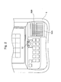
- Fig. 2 is an enlarged view of the operating part 5.
- the above-mentioned bill loading part 52 comprises a bill guide plate 51A and a mounting member 52B.
- the bill guide plate 52A and the mounting member 52B are integrated together and mounted to the operating part 5.
- the mounting member 52B forms a part of the door 3.
- Fig. 3 is a diagram showing a state in which the door 3 is opened.
- the bill validator 22 and a bill stacker 23 are installed inside the cabinet 2.
- the bill validator 22 determines the truth/falseness or quality of a bill loaded from the bill loading part 52.
- the bill stacker 23 houses bills validated by the bill validator 22.
- a bill guided by the bill loading part 52 is taken in by the bill validator 22 via a bill insertion slot 529.
- a drain bottle 7, which is a container, is mounted directly below the mounting member 52B.
- Fig. 4 is a perspective view of the bill guide plate 52A.
- a plurality of substantially rectilinear slit openings 521 are formed in parallel as a plurality of openings in the bill guide plate 52A.
- Slit openings 521 are disposed in parallel with each other.
- Slit openings 521 run along the direction from the bill insertion slot 529 to the outer side of the cabinet 2.
- the entirety of the opening of the slit opening 521 does not comprise a hole that passes through bill guide plate 52A. That is, a slit opening 521 is an open groove having a bottom formed by an opening bottom part 600.
- partition members 523 are formed on bill guide plate 52A.
- the partition members 523 partition each slit opening 521 into a plurality of small slit openings 524.
- the position of the upper surface of a partition member 523 is slightly lower than a bill guide surface 522.
- the length of each small slit opening 524 partitioned by partition members 523 is formed to be smaller than the diameter of a coin 10 used in the gaming machine.
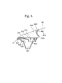
- Fig. 5 is a longitudinal sectional view of a state in which the bill guide plate 52A and the mounting member 52B are assembled together.
- the bill guide plate 52A is detachably mounted to a loading slot 520, which serves as a bill insertion space.
- the bill guide plate 52A extends outwards from the lower end of the bill insertion slot 529 that is positioned at a lower side of the loading slot 520.
- the peripheral walls that form loading slot 520 are connected to the cabinet2.
- the peripheral walls extends downwards and form a first opening 525 that opposes loading slot 520.
- the peripheral walls that form first opening 525 continue further downward and form a second opening 526 that is open in the downward direction.
- the loading slot 520, first opening part 525, and second opening part 526 form a space of substantially pyramidal shape with the apex at the lower side.
- the bill guide plate 52A is formed so as to cover the first opening part 525 from above.
- the first opening part 525 and second opening part 526 are for guiding liquid and other foreign matter that enter via the slit opening 521 from the exterior.
- Fig. 6 is an exploded perspective diagram of the bill loading part 52.
- a protrusion 528A is formed on the rear wall of the bill guide plate 52A.
- a cylindrical protrusion 528B is formed on the front lower wall of the bill guide plate 52A.
- An internal thread is formed in the cylindrical protrusion 528B.
- a groove 528C is formed in the rear inner wall of the first opening part 525 of mounting member 52B.
- the bill guide plate 52A is assembled onto the mounting member 52B by inserting the protrusion 528A of the bill guide plate 52A into the groove 528C and tilting the bill guide plate 52A towards the mounting member 52B.
- the bill guide plate 52A can also be separated from the mounting member 52B by movement in the opposite direction.
- the bill guide plate 52A and mounting member 52B are made integral by fixing the cylindrical protrusion 528B of the bill guide plate 52A to the mounting member 52B utilizing a fixing screw BF1.
- the integrated bill guide plate 52A and mounting member 52B are then inserted in a notched part of a control panel 50 of the operating part 5.
- the integrated bill guide plate 52A and mounting member 52B are then fixed by a fixing screw BF2 onto a mounting bracket 501, provided on the control panel 50, thus completing the assembly.
- an edge of the control panel 50 is inserted into a groove 527 formed in a front part of the mounting member 52B and the mounting member 52B is tilted towards control panel 50. And then a collar of the mounting member 52B comes in contact with the upper face of control panel 50. The mounting member 52B is then fixed to the control panel 50 by the fixing screw BF2 to attain the fixed state.
- Fig. 7 is a partial view of door 3 as seen from the rear face side.
- a drain bottle 7 is installed at the rear face side of door 3.
- An upper face opening 70 of the drain bottle 7 is positioned below a second opening 526 of mounting member 52B. That is, the drain bottle 7 is installed so that the center of gravity of the upper face opening 70 of the drain bottle is substantially matched with the center of gravity of the second opening 526. Also, the upper face opening 70 of the drain bottle 7 is made larger in cross-sectional area than the cross section of the second opening 526 at the lower end part.
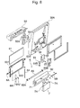
- Fig. 8 is an exploded perspective diagram of a frame body 6.
- a frame plate 632 is formed to a generally "U"-iike shape and houses a decorative panel plate 61.
- a cover 62 is mounted to the frame plate 632.
- a cylinder lock 6A for locking or unlocking the frame body 6 to or from the door 3.
- a through hole 633 At the right flank of the frame plate 632 is formed a through hole 633.
- a pivot 64 is inserted into the through hole 633 and the frame 6 is rotatably joined with the door 3.
- the decorative panel plate 61, cover 62, and frame plate 632 thus open and close integrally.
- the drain bottle 7 has a thin, laterally long shape.
- the drain bottle 7 is rectangular in horizontal cross-section in the part positioned below the upper face opening 70.
- the drain bottle 7 is mounted so as to face its one of long sides of the rectangular to the rear face of the cover 62.
- the drain bottle 7 is formed of a substance of substantially transparent or semi-transparent material (for example, glass or a synthetic resin).
- the storage capacity of the drain bottle 7 is approximately one liter or less. Due to being approximately one liter or less in the storage capacity, the drain bottle 7 can adequately contain a drink, etc., that is spilled onto the bill guide plate 52A. Also the drain bottle 7 can be installed suitably, for example, at the rear side of the door 3 since there is no need to make available a large space for installation.
- the bill guide plate 52A has a plurality of substantially rectilinear slit openings 521 formed in columns. Thus even when a drink or other foreign matter spills onto the bill guide plate, it can be collected through the slit openings 521. The foreign matter will not get on the various devices inside the cabinet and breakage of the various devices can be prevented.
- the bill guide plate 52A has the form of a bag with an open bottom and the inner peripheral walls form inclined faces with which a solution or other foreign matter that is thrown in can fall readily by gravity to the bottom face.
- each of the first opening 525 of the mounting member 52B and the second opening 526, which continues from the first opening 525, has the form of a bag with an open bottom and the inner peripheral walls form inclined faces with which a solution or other foreign matter that is thrown in can fall readily by gravity to the bottom face.
- the first opening 525 and second opening 526 which are positioned in the direction substantially below the slit openings 521, form a guide part that guides a solution or other foreign matter from the exterior. And by the drain bottle 7 equipped below the second opening 526 of the mounting member 52B as shown in Fig. 7, the foreign matter that is guided by the above-mentioned guide part can be collected in the drain bottle 7.
- the metal latches 71 of the cover 62 and pins 7A of the drain bottle 7 can be engaged and disengaged. That is, the drain bottle 7 is not formed integrally on the rear face of the door 3 but is mounted in a detachable manner. Thus even when foreign matter from the exterior accumulate in the drain bottle 7, the drain bottle 7 can be detached and the foreign matter can thus be discarded from drain bottle 7. Also, since the drain bottle 7 is mounted to the rear face of the door 3, the drain bottle 7 can be detached simply after opening the door 3 without being affected by the existence of other devices.
- the drain bottle 7 has a laterally long shape with which the horizontal cross section of the containment part positioned below the upper face opening 70 has a shape that is long in the lateral direction.
- the drain bottle 7 of the above-mentioned lateral direction is mounted so as to be set along the rear face of the cover 62.
- a bill validator 22 and a bill stacker 23 are disposed inside the cabinet 2.
- a coin guide 24 is also disposed inside the cabinet 2. Behind the coin guide 24 are mounted a printed circuit board for controlling the slot machine 1 and a shelf 25. Furthermore, an unillustrated hopper is disposed below the coin guide 24. Since the interior of the cabinet 2 is thus put in a crowded mounted state, a space by which the drain bottle 7 can protrude towards the interior of cabinet 2 does not exist.
- a coin allocating device which allocates a coin 10 loaded in from the coin slot 51 into the coin guide 24 or coin tray 30 is disposed adjacent mounting member 52B at the back face of door 3.
- drain bottle 7 is made thin and laterally long in shape.
- the drain bottle 7 is thus excellent in terms of saving space within the cabinet 2 and yet a relatively large amount of foreign matter can be collected in the containment part of the drain bottle 7 under the above-mentioned restrictions.
- the drain bottle 7 is formed of a substance of substantially transparent or semi-transparent material (for example, glass or a synthetic resin).
- the drain bottle 7 moves along with the door 3 or frame body 6, thus enabling the drain bottle 7 to be viewed.
- the drain bottle 7 By forming the drain bottle 7 of a substance of substantially transparent or semi-transparent material, the foreign matter collected in the drain bottle 7 can be viewed readily. The collected amount can thus be recognized without having to detach the drain bottle 7 each time to check the timing for discarding the foreign matter from the exterior.
- a gaming machine equipped with a bill guide plate for guiding a bill into a bill insertion slot, is equipped with a guide part, guiding foreign matter from the exterior, in the direction substantially below a opening that is equipped by the bill guide plate, and is equipped with a container, for collecting the foreign matter guided by the above-mentioned guide part, at the rear face side of the above-mentioned door.
- a foreign matter from the exterior which drops from the opening of the bill guide plate, can thus be collected in the container via the guide part to reduce the drawbacks of malfunction of the various devices inside the cabinet due to foreign matter from the exterior. This effect is especially prominent in the case where the foreign matter is liquid.
- an upper face opening of the above-mentioned container is positioned in a substantially downward direction below the above-mentioned guide part and has a larger cross-sectional area than the cross section of the lower end part of the guide part.
- the above-mentioned container is mounted to the rear face side of the above-mentioned door and is mounted in a manner enabling detachment from the rear face of the above-mentioned door.
- the container is thus not formed integral to the rear face of the door but is mounted in a detachable manner.
- the above-mentioned container has a laterally long shape with which a containment part positioned below the upper opening has a horizontal cross section of a shape that is long in the lateral direction. And the container is mounted so that the above-mentioned lateral direction is set along the rear face of the above-mentioned door.
- the shape of the container can thus be made extremely thin. This is thus excellent in terms of saving space within the cabinet and yet a relatively large amount of foreign matter can be collected in the containment part.
- the container being made of a substantially transparent or semitransparent material, the amount of foreign matter collected in the container can be viewed readily.
- the timing for discarding the foreign matter from the container can thus be recognized without having to detach and check the container each time.
Landscapes
- Physics & Mathematics (AREA)
- General Physics & Mathematics (AREA)
- Slot Machines And Peripheral Devices (AREA)
- Control Of Vending Devices And Auxiliary Devices For Vending Devices (AREA)
- Pharmaceuticals Containing Other Organic And Inorganic Compounds (AREA)
Abstract
Description
Claims (6)
- A gaming machine enabling the insertion of bills, the gaming machine comprising:wherein the door comprises:a cabinet; anda door, provided on a front face of the cabinet;a bill insertion slot;a bill guide plate, extending outwards from a lower end of the bill insertion slot and having an opening;a guide part, positioned in a direction substantially right under the opening of the bill guide plate and guiding foreign matter from an exterior, anda container, disposed at the rear face of the door for collecting the foreign matter.
- The gaming machine according to claim 1,
wherein an upper opening of the container is positioned in a substantially downward direction below the guide part and has a larger cross-sectional area than a cross section of the lower end part of the guide part. - The gaming machine according to claims 1 or 2,
wherein the container is detachably mounted to the rear face of the door. - The gaming machine according to any one of claims 1 to 3,
wherein the container is rectangular in horizontal cross-section, and
one of long sides of the rectangular faces to the rear face of the door when container is mounted to the door. - The gaming machine according to any one of claims1 to 4,
wherein the container is formed of a substantially transparent or semi-transparent material. - The gaming machine according to any one of claims 1 to 5,
wherein a storage capacity of the container is one liter or less.
Applications Claiming Priority (2)
| Application Number | Priority Date | Filing Date | Title |
|---|---|---|---|
| JP2002316730 | 2002-10-30 | ||
| JP2002316730A JP2004147880A (en) | 2002-10-30 | 2002-10-30 | Gaming machine |
Publications (3)
| Publication Number | Publication Date |
|---|---|
| EP1416453A2 true EP1416453A2 (en) | 2004-05-06 |
| EP1416453A3 EP1416453A3 (en) | 2006-03-29 |
| EP1416453B1 EP1416453B1 (en) | 2008-08-13 |
Family
ID=32089552
Family Applications (1)
| Application Number | Title | Priority Date | Filing Date |
|---|---|---|---|
| EP03025018A Expired - Lifetime EP1416453B1 (en) | 2002-10-30 | 2003-10-30 | Gaming machine with bill insertion slot |
Country Status (8)
| Country | Link |
|---|---|
| US (1) | US20040224776A1 (en) |
| EP (1) | EP1416453B1 (en) |
| JP (1) | JP2004147880A (en) |
| AT (1) | ATE404962T1 (en) |
| AU (1) | AU2003259573A1 (en) |
| DE (1) | DE60322815D1 (en) |
| ES (1) | ES2309264T3 (en) |
| ZA (1) | ZA200308471B (en) |
Families Citing this family (30)
| Publication number | Priority date | Publication date | Assignee | Title |
|---|---|---|---|---|
| JP4518841B2 (en) * | 2004-05-31 | 2010-08-04 | 株式会社平和 | Medals insertion device |
| JP4544940B2 (en) * | 2004-08-25 | 2010-09-15 | 沖電気工業株式会社 | Media processing device |
| USD525664S1 (en) * | 2004-10-01 | 2006-07-25 | Cole Joseph W | Gaming machine door |
| US7806770B2 (en) * | 2006-04-10 | 2010-10-05 | Bally Gaming, Inc. | Gaming machine having a mounting assembly for a flat panel display |
| JP2008307335A (en) * | 2007-06-18 | 2008-12-25 | Aruze Corp | Game machine |
| JP2009165804A (en) * | 2008-01-11 | 2009-07-30 | Aruze Corp | Gaming machine |
| US8764573B2 (en) * | 2008-10-08 | 2014-07-01 | Konami Gaming, Inc. | Gaming machine cabinet |
| USD626602S1 (en) * | 2008-11-12 | 2010-11-02 | Konami Gaming, Inc. | Twin-display |
| USD619660S1 (en) | 2009-03-09 | 2010-07-13 | Cole Joseph W | Gaming machine |
| US8641535B2 (en) * | 2009-12-03 | 2014-02-04 | Patent Rights Protection Group, Llc | Gaming machine cabinet construction and method |
| US8430756B2 (en) | 2010-05-11 | 2013-04-30 | Patent Rights Protection Group, Llc | Gaming machine cabinet with edge lighting |
| WO2012019218A1 (en) * | 2010-08-09 | 2012-02-16 | Ainsworth Game Technology Limited | Gaming machine |
| USD685435S1 (en) | 2012-07-25 | 2013-07-02 | Ags, Llc | Gaming machine |
| USD820915S1 (en) | 2015-09-22 | 2018-06-19 | Ags Llc | Gaming machine |
| USD813954S1 (en) | 2015-09-24 | 2018-03-27 | Ags Llc | Game tower |
| USD818048S1 (en) | 2015-10-05 | 2018-05-15 | Ags Llc | Gaming machine |
| US9997010B2 (en) | 2015-12-18 | 2018-06-12 | Ags Llc | Electronic gaming device with external lighting functionality |
| US10002488B2 (en) | 2015-12-17 | 2018-06-19 | Ags Llc | Electronic gaming device with call tower functionality |
| USD843473S1 (en) | 2017-04-07 | 2019-03-19 | Ags Llc | Gaming machine |
| USD865873S1 (en) | 2017-08-23 | 2019-11-05 | Ags Llc | Gaming machine |
| USD852890S1 (en) | 2017-11-30 | 2019-07-02 | Ags Llc | Gaming machine |
| USD899526S1 (en) | 2018-02-02 | 2020-10-20 | Ags Llc | Support structure for gaming machine display |
| USD939632S1 (en) | 2018-07-17 | 2021-12-28 | Ags Llc | Gaming machine |
| USD969926S1 (en) | 2019-04-24 | 2022-11-15 | Ags Llc | Gaming machine |
| USD978810S1 (en) | 2019-07-31 | 2023-02-21 | Ags Llc | LED matrix display |
| USD969927S1 (en) | 2019-08-02 | 2022-11-15 | Ags Llc | Gaming machine |
| US11380157B2 (en) | 2019-08-02 | 2022-07-05 | Ags Llc | Servicing and mounting features for gaming machine display screens and toppers |
| USD1032722S1 (en) | 2022-04-19 | 2024-06-25 | Ags Llc | Gaming machine |
| USD1032723S1 (en) | 2022-04-19 | 2024-06-25 | Ags Llc | Gaming machine |
| USD1105254S1 (en) | 2023-04-18 | 2025-12-09 | Ags Llc | Gaming machine |
Family Cites Families (7)
| Publication number | Priority date | Publication date | Assignee | Title |
|---|---|---|---|---|
| US4230213A (en) * | 1978-12-26 | 1980-10-28 | La Crosse Cooler Company, Inc. | Liquid rejecting coin chute |
| US4269297A (en) * | 1979-11-13 | 1981-05-26 | Aosco & Associates, Ltd. | Vending machine see-thru coin box |
| US5156250A (en) * | 1991-09-26 | 1992-10-20 | Mid-South Enterprises | Liquid diverter for currency receiver |
| US5318164A (en) * | 1992-05-15 | 1994-06-07 | Mars Incorporated | Vending machine apparatus and method to prevent fraud and minimize damage from injected fluids |
| US5566809A (en) * | 1992-06-02 | 1996-10-22 | Coin Acceptors, Inc. | Vending machine protective device |
| KR970005397B1 (en) * | 1992-07-29 | 1997-04-16 | 가부시끼가이샤 닛뽄곤락스 | Paper money identifying device |
| KR970007741B1 (en) * | 1993-03-31 | 1997-05-16 | 가부시끼가이샤 니뽄곤락스 | Bill processor |
-
2002
- 2002-10-30 JP JP2002316730A patent/JP2004147880A/en active Pending
-
2003
- 2003-10-30 EP EP03025018A patent/EP1416453B1/en not_active Expired - Lifetime
- 2003-10-30 AU AU2003259573A patent/AU2003259573A1/en not_active Abandoned
- 2003-10-30 AT AT03025018T patent/ATE404962T1/en active
- 2003-10-30 ES ES03025018T patent/ES2309264T3/en not_active Expired - Lifetime
- 2003-10-30 DE DE60322815T patent/DE60322815D1/en not_active Expired - Lifetime
- 2003-10-30 US US10/696,584 patent/US20040224776A1/en not_active Abandoned
- 2003-10-30 ZA ZA200308471A patent/ZA200308471B/en unknown
Also Published As
| Publication number | Publication date |
|---|---|
| EP1416453A3 (en) | 2006-03-29 |
| ZA200308471B (en) | 2004-04-19 |
| ES2309264T3 (en) | 2008-12-16 |
| EP1416453B1 (en) | 2008-08-13 |
| US20040224776A1 (en) | 2004-11-11 |
| DE60322815D1 (en) | 2008-09-25 |
| ATE404962T1 (en) | 2008-08-15 |
| JP2004147880A (en) | 2004-05-27 |
| AU2003259573A1 (en) | 2004-05-20 |
Similar Documents
| Publication | Publication Date | Title |
|---|---|---|
| EP1416453B1 (en) | Gaming machine with bill insertion slot | |
| EP1283505B1 (en) | Coin hopper in a gaming machine | |
| US20050107167A1 (en) | Gaming machine and game medium receiving unit mountable on gaming machine | |
| EP1416446B1 (en) | Gaming machine | |
| JP2005329073A (en) | Slot machine | |
| JP4131548B2 (en) | Slot machine | |
| JP2005329072A (en) | Slot machine | |
| JP4131545B2 (en) | Slot machine | |
| JP4693000B2 (en) | Amusement media receiving box and gaming machine | |
| JP4476239B2 (en) | Game machine | |
| AU2003259572A8 (en) | Gaming machine | |
| JP4131547B2 (en) | Slot machine | |
| EP1416452B1 (en) | Gaming machine with game medium diverting means | |
| JP4230092B2 (en) | Yugi Island | |
| JP3604097B2 (en) | Ballistic game machine aisle equipment | |
| JP2005329077A (en) | Slot machine | |
| JP6889755B2 (en) | Pachinko machine | |
| JP2974240B2 (en) | Ballistic game machine aisle equipment | |
| JP3088638B2 (en) | Ballistic game machine aisle equipment | |
| JP3335577B2 (en) | Pachinko machine | |
| JP3280911B2 (en) | Pachinko machine | |
| JPH11319292A (en) | Pachinko machine | |
| JP2007289577A (en) | Game machine | |
| JP2966319B2 (en) | Ballistic game machine aisle equipment | |
| JP2000153042A (en) | Pachinko machine |
Legal Events
| Date | Code | Title | Description |
|---|---|---|---|
| PUAI | Public reference made under article 153(3) epc to a published international application that has entered the european phase |
Free format text: ORIGINAL CODE: 0009012 |
|
| AK | Designated contracting states |
Kind code of ref document: A2 Designated state(s): AT BE BG CH CY CZ DE DK EE ES FI FR GB GR HU IE IT LI LU MC NL PT RO SE SI SK TR |
|
| AX | Request for extension of the european patent |
Extension state: AL LT LV MK |
|
| PUAL | Search report despatched |
Free format text: ORIGINAL CODE: 0009013 |
|
| AK | Designated contracting states |
Kind code of ref document: A3 Designated state(s): AT BE BG CH CY CZ DE DK EE ES FI FR GB GR HU IE IT LI LU MC NL PT RO SE SI SK TR |
|
| AX | Request for extension of the european patent |
Extension state: AL LT LV MK |
|
| 17P | Request for examination filed |
Effective date: 20060830 |
|
| 17Q | First examination report despatched |
Effective date: 20061010 |
|
| AKX | Designation fees paid |
Designated state(s): AT BE BG CH CY CZ DE DK EE ES FI FR GB GR HU IE IT LI LU MC NL PT RO SE SI SK TR |
|
| GRAP | Despatch of communication of intention to grant a patent |
Free format text: ORIGINAL CODE: EPIDOSNIGR1 |
|
| GRAS | Grant fee paid |
Free format text: ORIGINAL CODE: EPIDOSNIGR3 |
|
| GRAA | (expected) grant |
Free format text: ORIGINAL CODE: 0009210 |
|
| AK | Designated contracting states |
Kind code of ref document: B1 Designated state(s): AT BE BG CH CY CZ DE DK EE ES FI FR GB GR HU IE IT LI LU MC NL PT RO SE SI SK TR |
|
| REG | Reference to a national code |
Ref country code: GB Ref legal event code: FG4D |
|
| REG | Reference to a national code |
Ref country code: CH Ref legal event code: EP |
|
| REG | Reference to a national code |
Ref country code: IE Ref legal event code: FG4D |
|
| REF | Corresponds to: |
Ref document number: 60322815 Country of ref document: DE Date of ref document: 20080925 Kind code of ref document: P |
|
| REG | Reference to a national code |
Ref country code: ES Ref legal event code: FG2A Ref document number: 2309264 Country of ref document: ES Kind code of ref document: T3 |
|
| PG25 | Lapsed in a contracting state [announced via postgrant information from national office to epo] |
Ref country code: NL Free format text: LAPSE BECAUSE OF FAILURE TO SUBMIT A TRANSLATION OF THE DESCRIPTION OR TO PAY THE FEE WITHIN THE PRESCRIBED TIME-LIMIT Effective date: 20080813 |
|
| PG25 | Lapsed in a contracting state [announced via postgrant information from national office to epo] |
Ref country code: SI Free format text: LAPSE BECAUSE OF FAILURE TO SUBMIT A TRANSLATION OF THE DESCRIPTION OR TO PAY THE FEE WITHIN THE PRESCRIBED TIME-LIMIT Effective date: 20080813 Ref country code: FI Free format text: LAPSE BECAUSE OF FAILURE TO SUBMIT A TRANSLATION OF THE DESCRIPTION OR TO PAY THE FEE WITHIN THE PRESCRIBED TIME-LIMIT Effective date: 20080813 |
|
| PG25 | Lapsed in a contracting state [announced via postgrant information from national office to epo] |
Ref country code: BE Free format text: LAPSE BECAUSE OF FAILURE TO SUBMIT A TRANSLATION OF THE DESCRIPTION OR TO PAY THE FEE WITHIN THE PRESCRIBED TIME-LIMIT Effective date: 20080813 |
|
| PG25 | Lapsed in a contracting state [announced via postgrant information from national office to epo] |
Ref country code: DK Free format text: LAPSE BECAUSE OF FAILURE TO SUBMIT A TRANSLATION OF THE DESCRIPTION OR TO PAY THE FEE WITHIN THE PRESCRIBED TIME-LIMIT Effective date: 20080813 Ref country code: BG Free format text: LAPSE BECAUSE OF FAILURE TO SUBMIT A TRANSLATION OF THE DESCRIPTION OR TO PAY THE FEE WITHIN THE PRESCRIBED TIME-LIMIT Effective date: 20081113 |
|
| PG25 | Lapsed in a contracting state [announced via postgrant information from national office to epo] |
Ref country code: RO Free format text: LAPSE BECAUSE OF FAILURE TO SUBMIT A TRANSLATION OF THE DESCRIPTION OR TO PAY THE FEE WITHIN THE PRESCRIBED TIME-LIMIT Effective date: 20080813 Ref country code: SK Free format text: LAPSE BECAUSE OF FAILURE TO SUBMIT A TRANSLATION OF THE DESCRIPTION OR TO PAY THE FEE WITHIN THE PRESCRIBED TIME-LIMIT Effective date: 20080813 Ref country code: CZ Free format text: LAPSE BECAUSE OF FAILURE TO SUBMIT A TRANSLATION OF THE DESCRIPTION OR TO PAY THE FEE WITHIN THE PRESCRIBED TIME-LIMIT Effective date: 20080813 Ref country code: MC Free format text: LAPSE BECAUSE OF NON-PAYMENT OF DUE FEES Effective date: 20081031 Ref country code: PT Free format text: LAPSE BECAUSE OF FAILURE TO SUBMIT A TRANSLATION OF THE DESCRIPTION OR TO PAY THE FEE WITHIN THE PRESCRIBED TIME-LIMIT Effective date: 20090113 |
|
| REG | Reference to a national code |
Ref country code: CH Ref legal event code: PL |
|
| PLBE | No opposition filed within time limit |
Free format text: ORIGINAL CODE: 0009261 |
|
| STAA | Information on the status of an ep patent application or granted ep patent |
Free format text: STATUS: NO OPPOSITION FILED WITHIN TIME LIMIT |
|
| 26N | No opposition filed |
Effective date: 20090514 |
|
| PG25 | Lapsed in a contracting state [announced via postgrant information from national office to epo] |
Ref country code: EE Free format text: LAPSE BECAUSE OF FAILURE TO SUBMIT A TRANSLATION OF THE DESCRIPTION OR TO PAY THE FEE WITHIN THE PRESCRIBED TIME-LIMIT Effective date: 20080813 |
|
| PG25 | Lapsed in a contracting state [announced via postgrant information from national office to epo] |
Ref country code: LI Free format text: LAPSE BECAUSE OF NON-PAYMENT OF DUE FEES Effective date: 20081031 Ref country code: IE Free format text: LAPSE BECAUSE OF NON-PAYMENT OF DUE FEES Effective date: 20081030 Ref country code: CH Free format text: LAPSE BECAUSE OF NON-PAYMENT OF DUE FEES Effective date: 20081031 |
|
| PG25 | Lapsed in a contracting state [announced via postgrant information from national office to epo] |
Ref country code: SE Free format text: LAPSE BECAUSE OF FAILURE TO SUBMIT A TRANSLATION OF THE DESCRIPTION OR TO PAY THE FEE WITHIN THE PRESCRIBED TIME-LIMIT Effective date: 20081113 |
|
| PG25 | Lapsed in a contracting state [announced via postgrant information from national office to epo] |
Ref country code: LU Free format text: LAPSE BECAUSE OF NON-PAYMENT OF DUE FEES Effective date: 20081030 Ref country code: HU Free format text: LAPSE BECAUSE OF FAILURE TO SUBMIT A TRANSLATION OF THE DESCRIPTION OR TO PAY THE FEE WITHIN THE PRESCRIBED TIME-LIMIT Effective date: 20090214 Ref country code: CY Free format text: LAPSE BECAUSE OF FAILURE TO SUBMIT A TRANSLATION OF THE DESCRIPTION OR TO PAY THE FEE WITHIN THE PRESCRIBED TIME-LIMIT Effective date: 20080813 |
|
| PG25 | Lapsed in a contracting state [announced via postgrant information from national office to epo] |
Ref country code: TR Free format text: LAPSE BECAUSE OF FAILURE TO SUBMIT A TRANSLATION OF THE DESCRIPTION OR TO PAY THE FEE WITHIN THE PRESCRIBED TIME-LIMIT Effective date: 20080813 |
|
| PG25 | Lapsed in a contracting state [announced via postgrant information from national office to epo] |
Ref country code: GR Free format text: LAPSE BECAUSE OF FAILURE TO SUBMIT A TRANSLATION OF THE DESCRIPTION OR TO PAY THE FEE WITHIN THE PRESCRIBED TIME-LIMIT Effective date: 20081114 |
|
| PGFP | Annual fee paid to national office [announced via postgrant information from national office to epo] |
Ref country code: AT Payment date: 20101014 Year of fee payment: 8 |
|
| PGFP | Annual fee paid to national office [announced via postgrant information from national office to epo] |
Ref country code: IT Payment date: 20101025 Year of fee payment: 8 |
|
| PGFP | Annual fee paid to national office [announced via postgrant information from national office to epo] |
Ref country code: FR Payment date: 20111103 Year of fee payment: 9 Ref country code: ES Payment date: 20111026 Year of fee payment: 9 |
|
| REG | Reference to a national code |
Ref country code: ES Ref legal event code: PC2A Owner name: UNIVERSAL ENTERTAINMENT CORPORATION Effective date: 20120207 |
|
| REG | Reference to a national code |
Ref country code: DE Ref legal event code: R082 Ref document number: 60322815 Country of ref document: DE Representative=s name: TER MEER STEINMEISTER & PARTNER GBR PATENTANWA, DE |
|
| REG | Reference to a national code |
Ref country code: DE Ref legal event code: R082 Ref document number: 60322815 Country of ref document: DE Representative=s name: TER MEER STEINMEISTER & PARTNER PATENTANWAELTE, DE Effective date: 20120423 Ref country code: DE Ref legal event code: R081 Ref document number: 60322815 Country of ref document: DE Owner name: UNIVERSAL ENTERTAINMENT CORP., JP Free format text: FORMER OWNER: ARUZE CORP., TOKIO/TOKYO, JP Effective date: 20120423 |
|
| REG | Reference to a national code |
Ref country code: AT Ref legal event code: HC Ref document number: 404962 Country of ref document: AT Kind code of ref document: T Owner name: UNIVERSAL ENTERTAINMENT CORPORATION, JP Effective date: 20120427 |
|
| REG | Reference to a national code |
Ref country code: AT Ref legal event code: MM01 Ref document number: 404962 Country of ref document: AT Kind code of ref document: T Effective date: 20121030 |
|
| REG | Reference to a national code |
Ref country code: FR Ref legal event code: ST Effective date: 20130628 |
|
| PG25 | Lapsed in a contracting state [announced via postgrant information from national office to epo] |
Ref country code: AT Free format text: LAPSE BECAUSE OF NON-PAYMENT OF DUE FEES Effective date: 20121030 |
|
| PG25 | Lapsed in a contracting state [announced via postgrant information from national office to epo] |
Ref country code: FR Free format text: LAPSE BECAUSE OF NON-PAYMENT OF DUE FEES Effective date: 20121031 Ref country code: IT Free format text: LAPSE BECAUSE OF NON-PAYMENT OF DUE FEES Effective date: 20121030 |
|
| REG | Reference to a national code |
Ref country code: ES Ref legal event code: FD2A Effective date: 20140116 |
|
| PG25 | Lapsed in a contracting state [announced via postgrant information from national office to epo] |
Ref country code: ES Free format text: LAPSE BECAUSE OF NON-PAYMENT OF DUE FEES Effective date: 20121031 |
|
| PGFP | Annual fee paid to national office [announced via postgrant information from national office to epo] |
Ref country code: GB Payment date: 20151021 Year of fee payment: 13 Ref country code: DE Payment date: 20151022 Year of fee payment: 13 |
|
| REG | Reference to a national code |
Ref country code: DE Ref legal event code: R119 Ref document number: 60322815 Country of ref document: DE |
|
| GBPC | Gb: european patent ceased through non-payment of renewal fee |
Effective date: 20161030 |
|
| PG25 | Lapsed in a contracting state [announced via postgrant information from national office to epo] |
Ref country code: GB Free format text: LAPSE BECAUSE OF NON-PAYMENT OF DUE FEES Effective date: 20161030 Ref country code: DE Free format text: LAPSE BECAUSE OF NON-PAYMENT OF DUE FEES Effective date: 20170503 |