EP1416274A1 - Testelementanalysesystem - Google Patents
Testelementanalysesystem Download PDFInfo
- Publication number
- EP1416274A1 EP1416274A1 EP03024609A EP03024609A EP1416274A1 EP 1416274 A1 EP1416274 A1 EP 1416274A1 EP 03024609 A EP03024609 A EP 03024609A EP 03024609 A EP03024609 A EP 03024609A EP 1416274 A1 EP1416274 A1 EP 1416274A1
- Authority
- EP
- European Patent Office
- Prior art keywords
- test
- test element
- gripping
- elements
- frame
- Prior art date
- Legal status (The legal status is an assumption and is not a legal conclusion. Google has not performed a legal analysis and makes no representation as to the accuracy of the status listed.)
- Granted
Links
Images


Classifications
-
- G—PHYSICS
- G01—MEASURING; TESTING
- G01N—INVESTIGATING OR ANALYSING MATERIALS BY DETERMINING THEIR CHEMICAL OR PHYSICAL PROPERTIES
- G01N33/00—Investigating or analysing materials by specific methods not covered by groups G01N1/00 - G01N31/00
- G01N33/48—Biological material, e.g. blood, urine; Haemocytometers
- G01N33/50—Chemical analysis of biological material, e.g. blood, urine; Testing involving biospecific ligand binding methods; Immunological testing
- G01N33/52—Use of compounds or compositions for colorimetric, spectrophotometric or fluorometric investigation, e.g. use of reagent paper and including single- and multilayer analytical elements
- G01N33/525—Multi-layer analytical elements
Definitions
- the invention relates to a test element analysis system for analytical examination of a liquid sample as well Test elements for such an analysis system and a method for their manufacture.
- test elements For the qualitative and quantitative analysis of components a liquid sample, especially a body fluid of humans or animals, become large Scope of test procedures used with test elements work.
- the test elements contain reagents.
- to Carrying out a reaction is the test element with the Sample contacted.
- the reaction of sample and Reagent leads to a characteristic of the analysis Modification of the test element using a suitable Evaluation device is evaluated.
- the evaluation device is usually used to evaluate a very specific one Type of test elements from a particular manufacturer. Form the test elements and the evaluation device mutually coordinated components and are generally referred to as an analysis system.
- test elements There are numerous different types of test elements known by the measuring principle and the used Differentiate reagents and their structure.
- colorimetric analysis systems are particularly widespread. With you leads Reaction of the sample with those contained in the test element Reagents for a color change that are visual or measured by means of a photometric measuring device can be.
- electrochemical analysis systems attained great importance in which the reaction the sample with the reagents of the test element an electrically measurable change (an electrical Voltage or an electric current) that leads to a corresponding measuring electronics is measured.
- Test strips commonly used in the essentially from an elongated base layer made of plastic material and test fields attached to it.
- the test fields usually consist of one or several test layers containing reagents.
- Test strips are widely used especially for Blood and urine tests used.
- test elements With a second type of test element, which so far only is practically applied to a small extent Test field similar to a photographic slide from surrounded by a frame.
- Such test elements are called “Test vehicle with frame” and in English Technical literature referred to as “analysis slides”.
- the test field this type of test element usually consists of one or several test layers held by the frame and suitable for colorimetric tests Reagents included. After giving up the test on the The test field and the course of the test reaction can mostly on the opposite side (i.e. in the Rule of the bottom) of the test field, observed or be measured photometrically.
- test elements with frames are for example from the US patent 5,173,261.
- test element for immunoassays in EP 0312394 A2 described in which a membrane, the immunochemical Contains reagents in a truncated cone-shaped plastic part is clamped. The plastic part is on a syringe is placed around the syringe plunger to suck a liquid through the membrane and thereby the separation required for this type of test and allow free reagent components.
- test element reservoir as a magazine
- a transport device provided with a gripper, each one Takes test strips.
- test elements To be one in the field of blood sugar self-control Achieving simplified handling is described in the EP 0823635 proposed a special form of test elements where the test field in the end face of a bracket is integrated, the frustum of a cone or a frustum of a pyramid is trained. A majority of the Test elements are stacked in a tubular magazine stacked and held ready so that a appropriately trained evaluation device each on the top test element can be inserted in the magazine. A protrusion of the test element snaps into one corresponding recess on the head of the evaluation device a so that a connection between the test element and the evaluation device is manufactured. Then that will test element attached to the device with a drop of blood brought into contact, for example at the fingertip was generated. The elaborate form of this Test elements cause considerable costs. Still will handling compared to conventional test strips not much simplified.
- EP 0922959 describes an analysis system that a moisture-proof storage container for test elements and comprises an evaluation device.
- the evaluation device is provided with two guide grooves, namely a guide groove, the corresponding profiling of the test elements is matched and a second guide groove with a corresponding guide element of the storage container interacts.
- To a test element from the reservoir can be removed and in the test element holder of the evaluation device to place, both components are put together, being a direct takeover of a test element from the reservoir into the device. This makes handling easier, but it is Construction relatively complex and the material consumption for the manufacture of the test elements is proportionate high.
- the invention is based on the object to create a test element analysis system in which an improvement in handling, especially with regard to the removal of the test elements from a storage container and feeding them to a sample application position of the evaluation device is achieved with little effort.
- the construction should be simple and also for small, portable, battery-operated analysis systems are suitable.
- This task is carried out according to a first main aspect of the Invention solved by a test element analysis system, Comprehensive test elements with a test field that is designed to carry out brought into contact with the sample during an analysis , the reaction being one contained in the sample Analytes with at least one contained in the test element Reagent to a characteristic for the analysis Changes in a measured variable, and an evaluation device with a test element storage container on which a plurality of test elements for removal at a removal position is kept in stock, a sample application position of the test field of one test element with the Sample is brought into contact, a transport device, through which one test element each Removed position from the test element storage container and transported to the sample application position is, and a measuring device by means of a Test element is the characteristic quantity characteristic of the analysis is measured, in which the test elements frame surrounding the test field at least partially one around the outer circumference of the frame have outside facing gripping edge, the transport device a gripping device for gripping one each Has test element, and one test element for at least part of the transport route from the removal
- a test element analysis system comprising test elements with the properties explained above, a test element storage container in which a plurality of test elements are kept in stock for removal at a removal position of the storage container, and an evaluation device a test element holder for positioning each test element in a sample application position at which its test field is brought into contact with the sample, and with a measuring device for measuring the measurement variable characteristic of the analysis, in which the test elements enclose a frame that at least partially surrounds the test field have with an outward-facing gripping edge running around the outer periphery of the frame, the diameter of the frame increases from the gripping edge in both spatial directions (Z + and Z - ) running perpendicular to the test field plane, and the system includes a gripping device ies, by means of which a test element is held at its gripping edge when it is removed from the storage container.
- the invention also relates to such test element analysis systems suitable test elements, a the Storage container containing test elements and a method for their manufacture.
- the invention is for both colorimetric and suitable for electrochemical analysis systems.
- As a test field the area of the test element is designated here, which is brought into contact with the sample and thereby by the Sample is wetted.
- the frame that surrounds the test field does not have to be formed by a separate component. It is particularly with electrochemical test elements useful if the test field and the frame are in one piece are made of a plastic part, on or the required electrodes in the test field surface are integrated.
- the framework that the Test field at least partially surrounded, not by the sample wets and shows the on the outer circumference of the test element circumferential gripping edge.
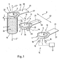
- test elements 1 shown in the figures have in each case a frame 3 surrounding a test field opening 2 and a test field 5 arranged in the test field opening 2 on.
- the test field 5 defines a (in the figures by two straight lines 4a and 4b) test field level.
- test field consists of a single layer or a layer composite of several firmly connected (usually containing different reagents) Layers.
- the invention can fundamentally but can also be used in connection with test fields, that of several loosely lying layers consist.
- the majority of the layers are in this Case fixed and held together by the frame 3, like this is described, for example, in US Pat. No. 5,173,261 is.
- electrochemical Test elements also designs possible where the test field and the frame are not separate parts.
- test elements 1 are disc-shaped in the sense that its thickness d in the axial direction Z is considerably smaller as their dimensions in the directions perpendicular to this.
- the one shown in supervision of the test field level circular (preferably rotationally symmetrical) shape test element 1 is preferred, but not essential necessary. Rather, the test elements 1 can also have an outer shape that differs from the circular shape. Therefore the term "disk-shaped” is not restrictive to be understood in the sense of "circular disk-shaped".
- An at least centrally symmetrical design with a curved boundary (for example an elliptical or oval shape) is preferred.
- a curved boundary for example an elliptical or oval shape
- the holder of round test elements in the gripping device is self-centering, the construction of the storage container in the form of a magazine ( Figure 5) is simpler and the relation between the size of the sample application area 18 and the total area of the test element 1 is particularly favorable. in principle is also a rectangular or even non-symmetrical Shaping of the test elements 1 possible.
- the Z direction perpendicular to the test field plane (which in the Case of a rotationally symmetrical test element with its Axis of symmetry coincides) as "axial direction” referred to, while the term “radial” for a parallel to the test field level from the center of the test field 5 away (or from its edge towards the center) Spatial direction is used.
- the liquid sample is on a sample application page 6 the test element 1 abandoned. It penetrates the test field and reacts with reagents contained in the test field. The reaction leads to the colorimetric shown Test for a characteristic for the analysis photometric measurable color change in an evaluation zone of the test field on the evaluation page 7 of the Test element 1, which lies opposite the sample application side 6.
- test elements 1 by means of a transport device 8 between several Functional positions moved.
- a removal position 9 on which a test element, preferably as a Magazine trained (only schematically indicated here) Storage container 10 is removed, a sample application position 11, on which the test element 1 with the sample 12 in Is brought into contact, and a measuring position 13 at which by means of a measuring device 14 one for analysis characteristic measured variable is measured.
- a measuring position 13 at which by means of a measuring device 14 one for analysis characteristic measured variable is measured.
- a reflection photometric Measuring device with a light transmitter 15, a light receiver 16 and a measuring and evaluation electronics 17. So the remission of the (shown in the Case formed from the bottom of the test field 5) Evaluation zone 19 measured.
- the transport device 8 grips and transports one test element 1 each by means of a gripping device 20, which is designed here as a gripping fork 21 with two arms 22 is.
- the area of the frame to which it is attached by the Poor is contacted is referred to as gripping edge 24. It is radially outward, i.e. from the center of the Test field 5 away, directed, on the outer circumference of the frame 3 peripheral surface at least in sections educated.
- the gripping arms can be in the gripping section 25 22 either in full area or in points stand to the gripping edge 24 of the frame 3.
- the gripping section 25 is the one between the first and last contact point lying part of the arms 22. It runs parallel to test field level 4.
- a gripping device designed as a gripping fork 21 20 will be a particularly space-saving and reliable Construction achieved, it is possible to entire transport of the test elements 1 between the functional positions of the evaluation device using a simple Swiveling movement of the gripping fork 21 around a fixed one Realizing axis.
- the Gripping device 21 In contrast to the known automatic test element analysis systems used grippers contacted the Gripping device 21 not the spatially extended upper and lower Underside of a base course, but a narrow one Gripping edge from the outside. Because the holding force in radial Direction from the outside inwards, the Gripping device 20 also referred to as a radial gripper become.
- the thickness of the test elements 1 (i.e. their maximum dimension in the axial direction) is preferably less than 3 mm. For a secure hold using the narrow To ensure gripping edge 24, it should at least 0.3 mm. The thickness is preferably 0.5 mm up to 1 mm.
- the frame area (area extension of the frame, considered in supervision of the test field level) preferred embodiment smaller, at least not much larger than the sample application area 18 of the Test field 5.
- the frame area is preferably at most three times the size of the sample application area 18 of the test field.
- Draw test elements 1 with a narrow frame are characterized by low material consumption and can can be stored very space-saving. That will be through the overall small dimensions of test elements according to the invention additionally supported.
- the largest Dimension of the test elements in the radial direction for round ones Test elements whose diameter) less than 10 mm, preferably less than 6 mm. In practical testing analysis elements with only about 4 mm Outside diameter and a diameter of the sample application area 18 by 3 mm (i.e. an edge width of 0.5 mm) used.
- the gripping arms 22 can each have a Swivel bearing with the rest of the gripping device 20 connected and mechanically movable.
- the grasp and Holding the test elements 1 required mobility rests on the fact that the arms 22 are so elastic with the remaining gripping device 20 that they are connected solely because of this elasticity (i.e. without the Arms 22 of the gripping fork 21 by an actuator must be moved) on or around that Test element can be pushed so that it is the test element hold tight.
- the elastic mobility preferably results from an inherent elasticity of the here of the Gripping fork 21 formed gripping element 26, i.e.
- the Gripping member 26 including arms 22 is relative a movement parallel to the test field level elastic deformable and designed so that it is under bending stress stands when a test element 1 is held.
- the gripping arms 22 are preferably as shown designed that their distance from the front end 28 of Gripping section 25 decreases.
- the gripping edge 24 one round test element 1 is from the arms 22 around encompassed more than 180 degrees. This is the fixation of the test element 1 in particular against slipping out due to a movement parallel to the test field level improved.
- the Gripping edge 24 of a straight running in the axial direction Z In the embodiment shown in Figure 1, the Gripping edge 24 of a straight running in the axial direction Z. Cylinder surface formed.
- the test element is only in terms of a displacement in the Z direction fixed by frictional connection. The possible holding force may be insufficient, for example if there is a drop of blood in the sample application position 11 is abandoned and the user (accidentally) presses against test element 1.
- the test element 1 falling out of the gripping fork 21 can avoid an additional device-side Support 29 may be provided on which the test element 1 rests when it is in the sample application position 11 located.
- FIGS. 2 to 11 show preferred embodiments in which the design of the profile of the frame 3 in the region of the gripping edge 24 improves the fixation of the test elements 1 on the gripping device 20.
- the diameter of the frame 3 extends from the gripping edge 24 in both directions Z + and Z - perpendicular to the test field plane 4a, 4b (i.e. with the horizontal position of the test elements 1 shown in the figures up and down ) increases.
- the gripping edge is therefore, viewed in the axial direction Z, at the location of the smallest diameter of the radially outward peripheral peripheral surface of the frame 3. This results in a positive locking of the test elements 1 on the gripping device 20 with respect to both axial spatial directions Z + and Z - reached.
- FIG Figures 2 to 7 A first embodiment of such test elements 1 is shown in FIG Figures 2 to 7 shown.
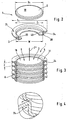
- the frame 3 Above the gripping edge 24, the frame 3 expands to a flange-like Shoulder 31.
- the material of shoulder 31 should (at least on the surface of the sample application side 6) hydrophobic (if necessary by surface treatment hydrophobized) to increase the hygienic effectiveness optimize.
- the shoulder 31 is preferably so wide that adjacent parts of the gripping device 20 (here the Gripping section 25 of the adjacent to the gripping edge 24 Arms 22) at least partially, preferably completely, of the shoulder 31 to be covered. This will cause contamination these parts and thus the evaluation device when loading the sample 12 in the sample loading position 11 prevented reliably and with little effort.
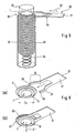
- test elements 1 are in a storage container 10 in the form of a tubular magazine 32 immediately stacked on top of each other. To them one by one by the translational indicated by arrow 37 Withdrawal movement at the same withdrawal position the stack 33 of test elements 1 for example by a spring 34 up against fixed counterpart 35 pressed.
- the one between the counterpart 35 and the upper limit of the housing of the Magazine 32 remaining removal slot 36 is something higher than the thickness d of a test element, so that each a test element can be removed from a gripping fork 21 can.
- test elements 1 In order to make this possible, the test elements 1 must be able to slide on one another in the stacked state. This sliding ability is supported by the profiling of the frame shown, which is characterized in that on one side (here the sample application side 6) its inner dimension D i is smaller, but its outer dimension D a is larger than the outer dimension D u (FIG. 6) on the opposite side (which should slide on the first side; here the evaluation side 7) is (ie D i ⁇ D u ⁇ D a ). With such a shape, test elements 1 stacked one on top of the other have an annular mechanical contact. The resulting advantageous pressure distribution reduces the risk that the test elements 1 stick together during a longer storage period.
- the profile of the frame 3 is also in terms of simple and reliable fixation of the test field 5 of importance in the framework 3.
- a Test field 5 produced separately from the frame 3 he preferably designed so that the frame 3 a Includes recess 40 for receiving the test field 5 and the depth of the receiving trough 40 is greater than the thickness of the test field 5, so that the circumferential boundary wall 38 of the receiving trough 40 the surface of one therein recorded test field 5. That’s why Test field 5 not with neighboring test elements in one Test element stack in contact.
- the boundary walls 38 of the receiving trough 40 have a negative slope on the lower part of their height dimension (ie they are inclined inwards from the bottom upward), so that the diameter of the receiving trough 40 is at the bottom thereof 39 is larger than above the ground.
- the test field 5 is fixed in the test field receiving trough 40 in that its clear width W (minimum dimension in a plane that runs parallel to the test field plane) is somewhat smaller than the diameter D f of the test field, so that the test field when inserted into the receiving trough 40 is slightly compressed in the radial direction.
- the test field material 5 is sufficiently elastic that it expands again after being inserted into the receiving trough 40 and is fixed in a snug fit in the receiving trough 40.
- the reservoir 10 is advantageously possible tightly closed to make the shelf life more sensitive to moisture Increase test items.
- a Magazine of the type shown in Figure 5 can Sufficient sealing effect by adjusting the inside diameter to the outside diameter of the test elements 1 and achieved by appropriate design of the counterpart 35 become.
- the test element storage container but also be open, for example if the test elements are not sensitive to environmental influences react or the container is in a sealed device housing located.
- Figures 7 to 9 show an embodiment, the particularly suitable in cases where the material of the test field 5 is not sufficiently elastic to fixed in the frame 3 in the manner described above to become.
- the fixation is done by flanging a fixing ridge provided at the edge of the test field recess 40 41 from the position shown in Figure 7 in the position shown in Figure 8.
- This requires, that the frame 3 from a plastically deformable Material such as metal. It can however, plastics can also be processed in this way.
- a particular advantage of the illustrated embodiment the invention is that the transport between the functional positions required in the evaluation device with a few simple mechanical movements is possible.
- Grasping a test element 1 requires just a simple translational relative movement (Arrow 37 in Fig. 5) of the gripping fork 21 on the stack of Test elements 1 to (or alternatively the stack of test elements 1 towards the gripping fork 21). Then it is enough a simple transverse movement - again parallel to that Test field level (arrow 43 in Fig. 1) - around the test element to the other function stations.
- it can as a pivoting movement of the gripping fork 21 by one stationary axis can be realized. This is very simple Way the complete automation of the analysis process possible in an evaluation device even if this has very compact dimensions and is battery operated is working.
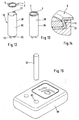
- the gripping element 26 of the gripping device 20 is an elongated gripping tube 50 with protruding at its upper end short arms 22 formed.
- the arms Based on the Test field 5 of test element 1, the arms extend 22 perpendicular to the test field plane (i.e. in the Z direction).
- the required mobility is based the arms 22 on the inherent elasticity of the here from the gripping tube 50 formed gripping element 26.
- the arms 22 are also in this case with respect to a movement elastically deformable parallel to the test field level, that the gripping tube by moving in the Z direction pushed from below over the frame 3 of the test element 1 can be, with the arms 22 through the test element 1 Hold contact with the gripping edge 24.
- Such an embodiment is for colorimetric analysis systems advantageous, being in the gripping tube at the same time
- Light guides 52, 53 can be integrated, which lead to the Einund Uncoupling the light serve.
- electrochemical Analysis systems can provide the necessary electrical Contacts in this embodiment as well also in the previously illustrated embodiments in the Gripping arms can be integrated.
- Another advantage of training the gripping device 20 is located as a gripping tube 50 in the radial for some device designs cheaper Towards space-saving geometry.
- the Gripping device 20 each with gripping arms 22 with the Gripping edge 24 in contact.
- the gripping device none (elastically mounted) gripping arms, but by Relative displacement of moving parts of the gripping edge like this is enclosed that a fixation by positive locking is achieved.
- the invention is not only about a fully automatic analysis system (as shown in Fig. 1), but also with a partially mechanized analysis system advantageous.
- the shape explained can of the test element in connection with a corresponding one Gripping device can be used to advantage Test elements from a storage container belonging to the system (especially magazine) and in a appropriate holder of the associated evaluation device use.
- An embodiment is particularly preferred, at (insofar as in agreement with the
- the gripping device is a component of the evaluation device is and the test element directly from the Removal position of the storage container on the evaluation device is taken over.
- Figures 15 to 17 show such a system, consisting from an evaluation device 60 and a magazine 32.
- Die 16 and 17 recognizable test element holder 61 includes a gripping device 20 with several (e.g. three) gripper arms 22.
- the gripping arms 22 are of this type positioned, trained and resiliently designed that they each take a test element 1 on its frame 3 and fix when the magazine 32 in the illustrated Way into a test element opening 62 of the evaluation device 60 is introduced. If the magazine 32 (in the figures is pulled upwards), the test element remains 1 in the holder formed by the gripper arms 22 back and is in a position in the it can be easily contacted with the sample. Subsequently does not find the evaluation using a here shown evaluation device instead.
Landscapes
- Health & Medical Sciences (AREA)
- Life Sciences & Earth Sciences (AREA)
- Hematology (AREA)
- Immunology (AREA)
- Engineering & Computer Science (AREA)
- Urology & Nephrology (AREA)
- Molecular Biology (AREA)
- Chemical & Material Sciences (AREA)
- Biomedical Technology (AREA)
- Physics & Mathematics (AREA)
- Biochemistry (AREA)
- Cell Biology (AREA)
- Food Science & Technology (AREA)
- Medicinal Chemistry (AREA)
- Biotechnology (AREA)
- Analytical Chemistry (AREA)
- Microbiology (AREA)
- General Health & Medical Sciences (AREA)
- General Physics & Mathematics (AREA)
- Pathology (AREA)
- Automatic Analysis And Handling Materials Therefor (AREA)
- Investigating Or Analysing Biological Materials (AREA)
- Testing Or Measuring Of Semiconductors Or The Like (AREA)
Abstract
Description
- einen Testelement-Vorratsbehälter, in dem eine Mehrzahl von Testelementen vorrätig gehalten wird,
- eine Probenaufgabeeinrichtung, an der das Testelement mit der Probe in Kontakt gebracht wird,
- eine Meßeinrichtung, mit der an einem in einer Meßposition (die mit der Probenaufgabeposition übereinstimmen oder von dieser verschieden sein kann) befindlichen Testelement eine für die Analyse charakteristische Meßgröße gemessen wird, und
- eine Transporteinrichtung, durch die je ein Testelement aus dem Testelement-Vorratsbehälter entnommen, zu der Probenaufgabeeinrichtung transportiert und erforderlichenfalls nach Kontaktierung mit der Probe zu der Meßposition weitertransportiert wird.
- Die Testelemente können einfach und kostengünstig hergestellt werden. Der zweckmäßigerweise aus Metall oder einem Kunststoffmaterial (das bevorzugt ein Polycarbonat oder einen Polyester enthält) hergestellte Rahmen kann sehr dünn und schmal gestaltet werden. Dadurch wird nicht nur der Materialverbrauch, sondern auch das Verpackungsvolumen der Testelemente reduziert, d.h. eine große Zahl von Testelementen kann in einem Magazin mit relativ geringem Volumen vorrätig gehalten werden. Entsprechend wird auch der Raumbedarf für einen zur Aufnahme verbrauchter Testelemente geeigneten Abfallbehälter reduziert.
- Die Transporteinrichtung automatischer Auswertegeräte kann mit einem Minimum beweglicher Teile sehr einfach konstruiert werden.
- Auch die teilweise Mechanisierung der Handhabungsschritte durch Verwendung eines Systems, das als funktional aufeinander abgestimmte Elemente einen speziellen Vorratsbehälter und ein entsprechendes Auswertegerät (wie bei der erwähnten EP 0922959) umfaßt, ist mit geringerem Aufwand möglich.
- Zugleich wird eine zuverlässige Funktion erreicht. Dies gilt in besonderem Maße, wenn das Querschnittsprofil des Rahmens im Bereich des Greifrandes so gestaltet ist, daß die Verbindung zwischen den Greifarmen und dem Testelement nicht nur auf Kraftschluß, sondern auf Formschluß basiert. Konkret wird dies dadurch erreicht, daß der Durchmesser des Rahmens von der Greiffläche aus in mindestens einer senkrecht zu der Testfeldebene verlaufenden Richtung unter Ausbildung einer vorspringenden Schulter zunimmt.
- Fig. 1
- eine perspektivische Prinzipsskizze der Bewegung einer Greifeinrichtung zum Transport eines Testelementes zwischen drei Funktionspositionen eines Auswertegerätes.
- Fig. 2
- eine perspektivische, teilweise aufgeschnittene Darstellung einer alternativen Ausführungsform eines Testelementes.
- Fig. 3
- eine perspektivische, teilweise aufgeschnittene Darstellung eines Stapels der Testelemente gemäß Figur 2.
- Fig. 4
- eine Detaildarstellung des Ausschnitts A aus Figur 3.
- Fig. 5
- eine perspektivische Darstellung eines Greifarmes bei der Entnahme eines Testelementes gemäß den Figuren 2 bis 4 aus einem röhrenförmigen Magazin.
- Fig. 6
- eine perspektivische Darstellung von zwei Bewegungsphasen (a) und (b) beim Ergreifen eines Testelementes mittels eines Greifarms.
- Fig. 7
- eine Darstellung entsprechend Figur 2 von einer weiteren alternativen Ausführungsform eines Testelementes.
- Fig. 8
- eine teilweise aufgeschnittene Darstellung des Testelementes gemäß Figur 7 mit eingesetztem und befestigtem Testfeld.
- Fig. 9
- eine Detaildarstellung des Ausschnitts B aus Figur 8.
- Fig. 10
- einen Querschnitt durch den Rahmen einer weiteren alternativen Ausführungsform eines Testelementes.
- Fig. 11
- eine Detaildarstellung des Ausschnitts C aus Figur 10.
- Fig. 12
- eine perspektivische Darstellung einer alternativen Ausführungsform einer Greifeinrichtung mit einem noch nicht ergriffenen Testelement.
- Fig. 13
- eine perspektivische Darstellung der Greifeinrichtung gemäß Figur 11 mit ergriffenem Testelement.
- Fig. 14
- eine Detaildarstellung zur Verdeutlichung des Zusammenwirkens der Greifarme und des Greifrandes bei der Ausführungsform der Figuren 12 und 13,
- Fig. 15
- eine perspektivische Darstellung eines teilmechanisierten Analysesystems,
- Fig. 16
- eine perspektivische, teilweise aufgeschnittene Darstellung des Systems nach Figur 15 während der Übernahme eines Testelementes aus einem Magazin in das Auswertegerät, und
- Fig. 17
- eine Detaildarstellung zu Figur 16.
- Die Rahmen 3 werden vorzugsweise durch plastisches Verformen einer Folie (vorzugsweise Kunststoffolie, jedoch kann auch eine Metallfolie verwendet werden), insbesondere durch Prägen oder Ziehen in die gewünschte Profilform gebracht.
- Zugleich oder anschließend wird erforderlichenfalls die Meßöffnung ausgestanzt, die im Fall colorimetrischer Testelemente die Auswertezone 19 umrahmt.
- Das Testfeld wird ebenfalls ausgestanzt, wobei die beschriebene Bedingung hinsichtlich dessen Durchmesser Df in Relation zu der lichten Weite W des Rahmens 3 eingehalten werden sollte.
- Das Testfeld 5 wird vorteilhafterweise mittels eines Stempels, dessen Außendurchmesser kleiner als die Testfeldöffnung 2, ist aus einem Zwischenträger heraus direkt in die Aufnahmemulde 40 gedrückt.
- Schließlich werden die fertigen Testelemente aus der Folie ausgestanzt, wobei die Dimensionen des Stanzwerkzeuges die äußere Begrenzung Da der Testelemente 1 bestimmen.
Claims (33)
- Testelementanalysesystem zur analytischen Untersuchung von flüssigen Proben, insbesondere von Körperflüssigkeiten von Menschen oder Tieren, umfassend Testelemente (1) mit einem Testfeld (5), das zur Durchführung einer Analyse mit der Probe in Kontakt gebracht wird, wobei die Reaktion eines in der Probe enthaltenden Analyten mit mindestens einem in dem Testelement (1) enthaltenen Reagenz zu einer für die Analyse charakteristischen Änderung einer Meßgröße führt, und
ein Auswertegerät mit
einem Testelement-Vorratsbehälter (10), in dem eine Mehrzahl von Testelementen (1) zur Entnahme an einer Entnahmeposition (9) vorrätig gehalten wird,
einer Probenaufgabeposition (11), an der das Testfeld (5) jeweils eines Testelementes (1) mit der Probe (12) in Kontakt gebracht wird,
einer Transporteinrichtung (8), durch die je ein Testelement (1) an der Entnahmeposition (9) aus dem Testelement-Vorratsbehälter (10) entnommen und zu der Probenaufgabeposition (11) transportiert wird, und
einer Meßeinrichtung (14), mittels der an einem Testelement (1) die für die Analyse charakteristische Meßgröße gemessen wird
bei welchem
die Testelemente (1) einen das Testfeld (5) wenigstens teilweise umgebenden Rahmen (3) mit einem am äußeren Umfang der Testelemente (1) umlaufenden nach außen gerichteten Greifrand (24) aufweisen und
die Transporteinrichtung (8) eine Greifeinrichtung (20) zum Greifen je eines Testelementes (1) aufweist, mittels der je ein Testelement (1) auf mindestens einem Teil des Transportweges von der Entnahmeposition (9) zu der Probenaufgabeposition (11) an seinem Greifrand festgehalten wird. - Testelementanalysesystem nach Anspruch 1, bei welchem die Meßgröße an einer von der Probenaufgabeposition verschiedenen Meßposition (13) gemessen und das Testelement auf mindestens einem Teil des Transportweges von der Probenaufgabeposition (11) zu der Meßposition (13) mittels der Greifeinrichtung (21) festgehalten wird.
- Testelementanalysesystem zur analytischen Untersuchung von flüssigen Proben, insbesondere von Körperflüssigkeiten von Menschen oder Tieren, umfassend Testelemente (1) mit einem Testfeld (5), das zur Durchführung einer Analyse mit der Probe in Kontakt gebracht wird, wobei die Reaktion eines in der Probe enthaltenden Analyten mit mindestens einem in dem Testelement (1) enthaltenen Reagenz zu einer für die Analyse charakteristischen Änderung einer Meßgröße führt,
einen Testelement-Vorratsbehälter (10), in dem eine Mehrzahl von Testelementen (1) zur Entnahme an einer Entnahmeposition (9) des Vorratsbehälters (10) vorrätig gehalten wird, und
ein Auswertegerät mit einer Testelement-Halterung zur Positionierung von jeweils einem Testelement in einer Probenaufgabeposition (11), an der sein Testfeld (5) mit der Probe (12) in Kontakt gebracht wird, und mit einer Meßeinrichtung (14) zum Messen der für die Analyse charakteristischen Meßgröße,
bei welchem
die Testelemente (1) einen das Testfeld (5) wenigstens teilweise umgebenden Rahmen (3) mit einem am äußeren Umfang der Testelemente (1) umlaufenden nach außen gerichteten Greifrand (24) aufweisen,
der Durchmesser des Rahmens (3) von dem Greifrand (24) aus in beiden senkrecht zu der Testfeldebene (4a,4b) verlaufenden Raumrichtungen (Z+ und Z-) zunimmt, und
das System eine Greifeinrichtung (20) einschließt, mittels der je ein Testelement (1) bei der Entnahme aus dem Vorratsbehälter (10) an seinem Greifrand gehalten wird. - Testelementanalysesystem nach Anspruch 3, bei welchem die Greifeinrichtung (20) ein Bestandteil des Auswertegerätes ist und das Testelement (1) unmittelbar von der Entnahmeposition des Vorratsbehälters in das Auswertegerät übernommen wird.
- Testelementanalysesystem nach einem der vorhergehenden Ansprüche, dadurch gekennzeichnet, daß die Greifeinrichtung eine Mehrzahl von Greifarmen (22) einschließt, die beim Festhalten eines Testelementes (1) dessen Greifrand (24) mindestens punktweise kontaktieren.
- Testelementanalysesystem nach Anspruch 5, bei welchem die Arme (22) der Greifeinrichtung (20) derartig elastisch beweglich sind, daß sie aufgrund der Elastizität auf das Testelement (1) geschoben werden können und das Testelement festhalten.
- Testelementanalysesystem nach Anspruch 6, bei welchem die Arme (22) der Greifeinrichtung (20) Bestandteil eines einstückig aus einem elastischen Material hergestellten Greifelementes (26) sind.
- Testelementanalysesystem nach einem der vorhergehenden Ansprüche, bei welchem der Testelement-Vorratsbehälter (10) ein Magazin (32) einschließt, in dem die Testelemente (1) stapelförmig übereinander gelagert sind.
- Testelementanalysesystem nach einem der vorhergehenden Ansprüche, bei welchem die Greifeinrichtung (20) als Greifgabel (21) mit zwei Greifarmen (22) ausgebildet ist und das Testelement (1) mittels den Greifrand (24) mindestens punktweise kontaktierenden parallel zu der Testfeldebene (4) verlaufenden Greifabschnitten (25) der Arme (22) der Greifgabel (21) festgehalten wird.
- Testelementanalysesystem nach Anspruch 9, bei welchem der Abstand zwischen den Armen (22) der Greifgabel (21) zum vorderen Ende (28) des Greifabschnittes (25) hin abnimmt.
- Testelementanalysesystem nach Anspruch 1 und einem der Ansprüche 9 oder 10, bei welchem die Transporteinrichtung (8) so ausgebildet ist, daß jeweils ein Testelement (1) mittels einer eindimensionalen translatorischen Bewegung der Greifgabel (21) aus dem Testelement-Vorratsbehälter (10) entnommen wird.
- Testelementanalysesystem nach Anspruch 1 und einem der Ansprüche 9 bis 11, bei welchem die Transporteinrichtung (8) so ausgebildet ist, daß jeweils ein Testelement (1) auf mindestens einem Teil des Transportweges zwischen der Entnahmeposition (9) und der Probenaufgabeposition (11) durch eine Schwenkbewegung der Greifgabel (21) um eine feste, senkrecht zu der Testfeldebene verlaufende Achse transportiert wird.
- Testelement für ein Analysesystem zur analytischen Untersuchung von Flüssigkeiten, insbesondere für ein System nach einem der Ansprüche 1 bis 12, mit einem ein Testfeld (5) mindestens teilweise umgebenden Rahmen (3),
bei welchem der Rahmen (3) an seinem äußeren Umfang einen nach außen gerichteten Greifrand (24) aufweist, der so ausgebildet ist, daß das Testelement (1) an dem Greifrand (24) von einer Greifeinrichtung (20) gehalten werden kann. - Testelement nach Anspruch 13, bei welchem die Fläche des Rahmens (3) auf der Probenaufgabeseite (6) des Testelementes (1) höchstens dreimal so groß wie die Probenaufgabefläche (18) des Testfeldes (5) ist.
- Testelement nach einem der Ansprüche 13 oder 14, dessen Dicke (d) mindestens 0,3 mm und höchstens 3 mm beträgt.
- Testelement nach einem der Ansprüche 13 bis 15, welches in Aufsicht auf das Testfeld kreisrund ist.
- Testelement nach einem der Ansprüche 13 bis 16, dessen Querschnittsprofil so gestaltet ist, daß mehrere übereinander gestapelte Testelemente gegeneinander in Richtung der Testfeldebene (4a,4b) gleiten können, ohne zu verhaken.
- Testelement nach einem der Ansprüche 13 bis 17, bei welchem der Durchmesser des Rahmens (3) von dem Greifrand (24) aus in einer senkrecht zu der Testfeldebene (4a,4b) verlaufenden Raumrichtung (Z+) unter Ausbildung einer vorspringenden Schulter (31) zunimmt.
- Testelement nach Anspruch 18, bei welchem die vorspringende Schulter (31) so ausgebildet ist, daß die der Schulter benachbarten Teile der Greifeinrichtung (20) von ihr abgedeckt werden.
- Testelement nach Anspruch 19, bei welchem die Oberfläche der vorspringenden Schulter zumindest auf der Probenaufgabeseite hydrophob ist.
- Testelement nach einem der Ansprüche 18 bis 20, bei welchem der Durchmesser des Rahmens (3) von dem Greifrand (24) aus in beide Richtungen (Z+ und Z-) zunimmt.
- Testelement nach einem der Ansprüche 13 bis 21, bei welchem der Rahmen (3) aus Metall oder einem Kunststoffmaterial hergestellt ist.
- Testelement nach einem der Ansprüche 13 bis 22, bei welchem der Rahmen (3) eine Aufnahmemulde (40) zur Aufnahme des Testfeldes (5) umschließt und die Tiefe der Aufnahmemulde (40) größer als die Dicke des Testfeldes (5) ist, so daß die umlaufende Begrenzungswand (38) der Aufnahmemulde (40) die Oberfläche eines darin aufgenommenen Testfelds (5) überragt.
- Testelement nach Anspruch 23, bei welchem das Testfeld (5) ein getrennt von dem Rahmen (3) hergestelltes Teil ist, das in der Aufnahmemulde (40) fixiert ist.
- Testelement nach Anspruch 24, bei welchem das Testfeld aus mehreren übereinander angeordneten Testschichten besteht.
- Testelement nach einem der Ansprüche 24 oder 25, bei welchem die Begrenzungswände (38) der Aufnahmemulde (40) auf einem Teilabschnitt ihrer Höhendimension eine negative Steigung haben, so daß der Durchmesser der Aufnahmemulde (40) an deren Boden (39) größer als oberhalb ihres Bodens (39) ist und das Testfeld (5) in der Aufnahmemulde (40) dadurch fixiert ist, daß die lichte Weite (W) der Aufnahmemulde (40) geringer als die Außendimension (Df) des Testfeldes ist, so daß das Testfeld beim Einsetzen in die Aufnahmemulde (40) radial komprimiert wird.
- Verfahren zur Herstellung von Testelementen nach einem der Ansprüche 13 bis 26, bei welchem das Profil des Randes durch plastisches Verformen einer Kunststoff- oder Metallfolie hergestellt wird.
- Verfahren nach Anspruch 27 zur Herstellung von Testelementen nach einem der Ansprüche 23 bis 26, welches ein Verfahrensschritt einschließt, bei dem die Aufnahmemulden (40) zur Aufnahme einer Mehrzahl von Testfeldern (5) durch Verformen einer Kunststoffoder Metallfolie erzeugt werden.
- Verfahren nach Anspruch 28 zur Herstellung von Analyseelementen nach einem der Ansprüche 24 bis 26, bei welchem in eine Mehrzahl von in einer Folie erzeugten Aufnahmemulden (40) Testfelder (5) eingebracht und fixiert und danach die Testelemente aus der Folie ausgestanzt werden.
- Testelement-Vorratsbehälter, enthaltend eine Mehrzahl von Testelementen (1) nach einem der Ansprüche 13 bis 26.
- Testelement-Vorratsbehälter nach Anspruch 30, welcher ein Magazin (32) einschließt, in dem die Testelemente (1) stapelförmig übereinander gelagert sind.
- Testelement-Vorratsbehälter nach Anspruch 31, wobei das Magazin (32) röhrenförmig ausgebildet ist und einen parallel zu der Testfeldebene (4) von darin enthaltenen Testelementen (1) verlaufenden Entnahmeschlitz (36) aufweist, der etwas höher ist, als die Dicke (d) eines Testelementes (1), so daß jeweils ein Testelement (1) von einer Greifeinrichtung (20) durch den Entnahmeschlitz (36) aus dem Magazin (32) entnommen werden kann.
- Testelement-Vorratsbehälter nach Anspruch 31, dessen Innenquerschnitt so auf den Außenquerschnitt der darin enthaltenen Testelemente (1) abgestimmt ist, daß die Rahmen (3) der Testelemente (1) in dichtendem Kontakt zu der Innenwand des Testelement-Vorratsbehälters (10) stehen.
Applications Claiming Priority (2)
| Application Number | Priority Date | Filing Date | Title |
|---|---|---|---|
| DE10250331 | 2002-10-29 | ||
| DE10250331 | 2002-10-29 |
Publications (2)
| Publication Number | Publication Date |
|---|---|
| EP1416274A1 true EP1416274A1 (de) | 2004-05-06 |
| EP1416274B1 EP1416274B1 (de) | 2008-05-21 |
Family
ID=32087268
Family Applications (1)
| Application Number | Title | Priority Date | Filing Date |
|---|---|---|---|
| EP03024609A Expired - Lifetime EP1416274B1 (de) | 2002-10-29 | 2003-10-25 | Testelementanalysesystem |
Country Status (6)
| Country | Link |
|---|---|
| US (1) | US7510682B2 (de) |
| EP (1) | EP1416274B1 (de) |
| JP (1) | JP2004151100A (de) |
| AT (1) | ATE396398T1 (de) |
| CA (1) | CA2447164A1 (de) |
| DE (2) | DE10349914A1 (de) |
Cited By (1)
| Publication number | Priority date | Publication date | Assignee | Title |
|---|---|---|---|---|
| WO2006047135A1 (en) * | 2004-10-21 | 2006-05-04 | Bayer Healthcare Llc | Sensor-dispensing device and mechanism for extracting sensor |
Families Citing this family (8)
| Publication number | Priority date | Publication date | Assignee | Title |
|---|---|---|---|---|
| DE102004036474A1 (de) | 2004-07-28 | 2006-03-23 | Roche Diagnostics Gmbh | Analysesystem zur Analyse einer Probe auf einem Testelement |
| US20080019870A1 (en) * | 2006-07-21 | 2008-01-24 | Michael John Newman | Integrated medical device dispensing and lancing mechanisms and methods of use |
| US9744535B2 (en) * | 2010-04-19 | 2017-08-29 | Roche Molecular Systems, Inc. | Cassette with multiwell plates |
| DE102012112508B3 (de) | 2012-12-18 | 2013-12-24 | Sartorius Lab Instruments Gmbh & Co. Kg | Handhabungswerkzeug für Prüfgewichte und Gewichtskasten |
| KR101812296B1 (ko) * | 2016-11-23 | 2017-12-26 | 주식회사 바이탈스미스 | 여성호르몬(에스트로겐)주기 예측 분석을 위한 영상 처리 시스템 |
| WO2018079915A1 (ko) * | 2016-10-28 | 2018-05-03 | 주식회사 바이탈스미스 | 배란일 예측 분석을 위한 영상 처리 시스템 |
| GB201711465D0 (en) * | 2017-07-17 | 2017-08-30 | Univ Oxford Innovation Ltd | Centrifuge tube handling device |
| CN109813904A (zh) * | 2019-03-27 | 2019-05-28 | 丁建红 | 非洲猪瘟病毒快速检测卡 |
Citations (4)
| Publication number | Priority date | Publication date | Assignee | Title |
|---|---|---|---|---|
| US5173261A (en) * | 1990-04-14 | 1992-12-22 | Boehringer Mannheim Gmbh | Test carrier for the analysis of fluids |
| US5332549A (en) * | 1992-07-01 | 1994-07-26 | Pb Diagnostic Systems, Inc. | Assay module transport apparatus for use in an automated analytical instrument |
| EP0654668A1 (de) * | 1993-11-22 | 1995-05-24 | Fuji Photo Film Co., Ltd. | Kassette für chemische Analysenelemente |
| US6176119B1 (en) * | 1997-12-13 | 2001-01-23 | Roche Diagnostics Gmbh | Analytical system for sample liquids |
Family Cites Families (14)
| Publication number | Priority date | Publication date | Assignee | Title |
|---|---|---|---|---|
| US2608433A (en) * | 1945-06-06 | 1952-08-26 | Marbeuf Armand Jean | Tongs for test tubes or the like |
| US3932133A (en) | 1973-07-31 | 1976-01-13 | Olympus Optical Co., Ltd. | System for detecting the particular chemical component of a test fluid |
| US4118280A (en) | 1976-05-03 | 1978-10-03 | Mcdonnell Douglas Corporation | Automated microbial analyzer |
| DE2803849C2 (de) | 1978-01-30 | 1984-02-02 | Clinicon International Gmbh, 6800 Mannheim | Gerät zum Auswerten von Teststreifen |
| US4876204A (en) | 1984-10-11 | 1989-10-24 | Kabushiki Kaisha Kyoto Daiichi Kagaku | Method and apparatus of automatic continuous analysis using analytical implement |
| US4691009A (en) * | 1984-12-26 | 1987-09-01 | Repligen Corporation | Hybrid proteins produced by an ultrahigh prokaryotic expression system |
| JPH087220B2 (ja) | 1987-03-12 | 1996-01-29 | 富士写真フイルム株式会社 | 化学分析スライドを用いる分析方法 |
| JPS646872A (en) * | 1987-06-30 | 1989-01-11 | Konishiroku Photo Ind | Chemical analyzer |
| US4874691A (en) | 1987-10-16 | 1989-10-17 | Quadra Logic Technologies Inc. | Membrane-supported immunoassays |
| DE3940152A1 (de) | 1989-12-05 | 1991-06-06 | Boehringer Mannheim Gmbh | Teststreifenauswertegeraet fuer mehrfachteststreifen |
| US5258163A (en) | 1990-04-14 | 1993-11-02 | Boehringer Mannheim Gmbh | Test carrier for analysis of fluids |
| US5075079A (en) * | 1990-05-21 | 1991-12-24 | Technicon Instruments Corporation | Slide analysis system |
| TW227042B (de) * | 1991-12-19 | 1994-07-21 | Eastman Kodak Co | |
| US5846486A (en) | 1996-08-09 | 1998-12-08 | Lifescan, Inc. | Hollow frustum reagent test device |
-
2003
- 2003-10-25 DE DE10349914A patent/DE10349914A1/de not_active Withdrawn
- 2003-10-25 DE DE50309876T patent/DE50309876D1/de not_active Expired - Lifetime
- 2003-10-25 EP EP03024609A patent/EP1416274B1/de not_active Expired - Lifetime
- 2003-10-25 AT AT03024609T patent/ATE396398T1/de not_active IP Right Cessation
- 2003-10-28 JP JP2003367318A patent/JP2004151100A/ja not_active Ceased
- 2003-10-28 CA CA002447164A patent/CA2447164A1/en not_active Abandoned
- 2003-10-29 US US10/696,360 patent/US7510682B2/en not_active Expired - Fee Related
Patent Citations (4)
| Publication number | Priority date | Publication date | Assignee | Title |
|---|---|---|---|---|
| US5173261A (en) * | 1990-04-14 | 1992-12-22 | Boehringer Mannheim Gmbh | Test carrier for the analysis of fluids |
| US5332549A (en) * | 1992-07-01 | 1994-07-26 | Pb Diagnostic Systems, Inc. | Assay module transport apparatus for use in an automated analytical instrument |
| EP0654668A1 (de) * | 1993-11-22 | 1995-05-24 | Fuji Photo Film Co., Ltd. | Kassette für chemische Analysenelemente |
| US6176119B1 (en) * | 1997-12-13 | 2001-01-23 | Roche Diagnostics Gmbh | Analytical system for sample liquids |
Cited By (2)
| Publication number | Priority date | Publication date | Assignee | Title |
|---|---|---|---|---|
| WO2006047135A1 (en) * | 2004-10-21 | 2006-05-04 | Bayer Healthcare Llc | Sensor-dispensing device and mechanism for extracting sensor |
| US8142733B2 (en) | 2004-10-21 | 2012-03-27 | Bayer Healthcare Llc | Sensor-dispensing device and mechanism for extracting sensor |
Also Published As
| Publication number | Publication date |
|---|---|
| JP2004151100A (ja) | 2004-05-27 |
| EP1416274B1 (de) | 2008-05-21 |
| CA2447164A1 (en) | 2004-04-29 |
| DE50309876D1 (de) | 2008-07-03 |
| DE10349914A1 (de) | 2004-05-13 |
| US7510682B2 (en) | 2009-03-31 |
| US20040141881A1 (en) | 2004-07-22 |
| ATE396398T1 (de) | 2008-06-15 |
Similar Documents
| Publication | Publication Date | Title |
|---|---|---|
| DE69825107T2 (de) | Unterdruckerzeugungsvorrichtung und Probenanalysenvorrichtung zur Verwendung mit einer solchen Unterdruckerzeugungsvorrichtung | |
| DE1673340C3 (de) | ||
| DE10360786B4 (de) | Analysehandgerät | |
| DE69109998T2 (de) | Abgabesystem fuer fluessigkeiten mit pipette mit voreinstellbarer position fuer die spitze. | |
| DE69429159T2 (de) | Verfahren für einen spezifischen Bindungstest mit magnetischen Teilchen | |
| DE69602887T2 (de) | Vorrichtung zur Handhabung von mehreren Sensoren in einem Glukose-Überwachungsinstrument | |
| EP0618443A1 (de) | Teststreifenanalysesystem | |
| EP3162443B1 (de) | Nadelführung mit zentrierung für septum-piercing | |
| DE4427725C2 (de) | Meßeinrichtung zur Analyse von Flüssigkeiten | |
| DE212006000074U1 (de) | Vorrichtungen zum Erfassen von Analyten in flüssigen Proben | |
| DE10300702A1 (de) | Pipettenspitzen-Nachladesystem | |
| EP0676643A2 (de) | System zur kontaminationsfreien Bearbeitung von Reaktionsabläufen | |
| EP2908139A2 (de) | Transportvorrichtung, Probenverteilungssystem und Laborautomatisierungssystem | |
| EP0871033A2 (de) | Teststreifenpackung und Messgerät zur Verwendung einer solchen | |
| DE4323672A1 (de) | Vorrichtung zur gleichzeitigen Bestimmung von Analyten | |
| DE212006000063U1 (de) | Vorrichtung zur Erfassung von Analyten in flüssigen Proben | |
| EP1726950A1 (de) | Magazin zur Aufnahme von Testelementen | |
| EP0452740A1 (de) | Testträger für die Analyse von Flüssigkeiten | |
| EP2457660A1 (de) | Vorrichtung für einen Teststreifenhalter, Verfahren und Anordnung | |
| EP1416274B1 (de) | Testelementanalysesystem | |
| DE3883730T2 (de) | Vorrichtung zum einmaligen Gebrauch zur Entnahme und Aufbewahrung von Blutproben. | |
| EP1460429A2 (de) | Probenbehandlungsgerät, insbesondere automatisches Analysegerät mit einer Gefässhalterungseinrichtung | |
| EP0376111B1 (de) | Testträger-Analysesystem | |
| EP3013478B1 (de) | Vorrichtung und verfahren zur aufbewahrung und zum transport einer körperflüssigkeitsprobe | |
| EP3270167A1 (de) | Transport von flüssigkeitsbehältern in einem automatischen analysegerät |
Legal Events
| Date | Code | Title | Description |
|---|---|---|---|
| PUAI | Public reference made under article 153(3) epc to a published international application that has entered the european phase |
Free format text: ORIGINAL CODE: 0009012 |
|
| 17P | Request for examination filed |
Effective date: 20031025 |
|
| AK | Designated contracting states |
Kind code of ref document: A1 Designated state(s): AT BE BG CH CY CZ DE DK EE ES FI FR GB GR HU IE IT LI LU MC NL PT RO SE SI SK TR |
|
| AX | Request for extension of the european patent |
Extension state: AL LT LV MK |
|
| AKX | Designation fees paid |
Designated state(s): AT BE BG CH CY CZ DE DK EE ES FI FR GB GR HU IE IT LI LU MC NL PT RO SE SI SK TR |
|
| 17Q | First examination report despatched |
Effective date: 20061229 |
|
| GRAP | Despatch of communication of intention to grant a patent |
Free format text: ORIGINAL CODE: EPIDOSNIGR1 |
|
| GRAS | Grant fee paid |
Free format text: ORIGINAL CODE: EPIDOSNIGR3 |
|
| GRAA | (expected) grant |
Free format text: ORIGINAL CODE: 0009210 |
|
| AK | Designated contracting states |
Kind code of ref document: B1 Designated state(s): AT BE BG CH CY CZ DE DK EE ES FI FR GB GR HU IE IT LI LU MC NL PT RO SE SI SK TR |
|
| REG | Reference to a national code |
Ref country code: GB Ref legal event code: FG4D Free format text: NOT ENGLISH |
|
| REG | Reference to a national code |
Ref country code: CH Ref legal event code: EP |
|
| REF | Corresponds to: |
Ref document number: 50309876 Country of ref document: DE Date of ref document: 20080703 Kind code of ref document: P |
|
| REG | Reference to a national code |
Ref country code: IE Ref legal event code: FG4D Free format text: LANGUAGE OF EP DOCUMENT: GERMAN |
|
| PG25 | Lapsed in a contracting state [announced via postgrant information from national office to epo] |
Ref country code: SI Free format text: LAPSE BECAUSE OF FAILURE TO SUBMIT A TRANSLATION OF THE DESCRIPTION OR TO PAY THE FEE WITHIN THE PRESCRIBED TIME-LIMIT Effective date: 20080521 |
|
| PG25 | Lapsed in a contracting state [announced via postgrant information from national office to epo] |
Ref country code: FI Free format text: LAPSE BECAUSE OF FAILURE TO SUBMIT A TRANSLATION OF THE DESCRIPTION OR TO PAY THE FEE WITHIN THE PRESCRIBED TIME-LIMIT Effective date: 20080521 Ref country code: ES Free format text: LAPSE BECAUSE OF FAILURE TO SUBMIT A TRANSLATION OF THE DESCRIPTION OR TO PAY THE FEE WITHIN THE PRESCRIBED TIME-LIMIT Effective date: 20080901 |
|
| NLV1 | Nl: lapsed or annulled due to failure to fulfill the requirements of art. 29p and 29m of the patents act | ||
| PG25 | Lapsed in a contracting state [announced via postgrant information from national office to epo] |
Ref country code: NL Free format text: LAPSE BECAUSE OF FAILURE TO SUBMIT A TRANSLATION OF THE DESCRIPTION OR TO PAY THE FEE WITHIN THE PRESCRIBED TIME-LIMIT Effective date: 20080521 |
|
| REG | Reference to a national code |
Ref country code: IE Ref legal event code: FD4D |
|
| PG25 | Lapsed in a contracting state [announced via postgrant information from national office to epo] |
Ref country code: PT Free format text: LAPSE BECAUSE OF FAILURE TO SUBMIT A TRANSLATION OF THE DESCRIPTION OR TO PAY THE FEE WITHIN THE PRESCRIBED TIME-LIMIT Effective date: 20081021 Ref country code: CZ Free format text: LAPSE BECAUSE OF FAILURE TO SUBMIT A TRANSLATION OF THE DESCRIPTION OR TO PAY THE FEE WITHIN THE PRESCRIBED TIME-LIMIT Effective date: 20080521 Ref country code: DK Free format text: LAPSE BECAUSE OF FAILURE TO SUBMIT A TRANSLATION OF THE DESCRIPTION OR TO PAY THE FEE WITHIN THE PRESCRIBED TIME-LIMIT Effective date: 20080521 Ref country code: IE Free format text: LAPSE BECAUSE OF FAILURE TO SUBMIT A TRANSLATION OF THE DESCRIPTION OR TO PAY THE FEE WITHIN THE PRESCRIBED TIME-LIMIT Effective date: 20080521 Ref country code: SE Free format text: LAPSE BECAUSE OF FAILURE TO SUBMIT A TRANSLATION OF THE DESCRIPTION OR TO PAY THE FEE WITHIN THE PRESCRIBED TIME-LIMIT Effective date: 20080821 |
|
| PG25 | Lapsed in a contracting state [announced via postgrant information from national office to epo] |
Ref country code: SK Free format text: LAPSE BECAUSE OF FAILURE TO SUBMIT A TRANSLATION OF THE DESCRIPTION OR TO PAY THE FEE WITHIN THE PRESCRIBED TIME-LIMIT Effective date: 20080521 Ref country code: RO Free format text: LAPSE BECAUSE OF FAILURE TO SUBMIT A TRANSLATION OF THE DESCRIPTION OR TO PAY THE FEE WITHIN THE PRESCRIBED TIME-LIMIT Effective date: 20080521 |
|
| PLBE | No opposition filed within time limit |
Free format text: ORIGINAL CODE: 0009261 |
|
| STAA | Information on the status of an ep patent application or granted ep patent |
Free format text: STATUS: NO OPPOSITION FILED WITHIN TIME LIMIT |
|
| 26N | No opposition filed |
Effective date: 20090224 |
|
| BERE | Be: lapsed |
Owner name: ROCHE DIAGNOSTICS G.M.B.H. Effective date: 20081031 Owner name: F. HOFFMANN-LA ROCHE A.G. Effective date: 20081031 |
|
| PG25 | Lapsed in a contracting state [announced via postgrant information from national office to epo] |
Ref country code: BG Free format text: LAPSE BECAUSE OF FAILURE TO SUBMIT A TRANSLATION OF THE DESCRIPTION OR TO PAY THE FEE WITHIN THE PRESCRIBED TIME-LIMIT Effective date: 20080821 Ref country code: EE Free format text: LAPSE BECAUSE OF FAILURE TO SUBMIT A TRANSLATION OF THE DESCRIPTION OR TO PAY THE FEE WITHIN THE PRESCRIBED TIME-LIMIT Effective date: 20080521 |
|
| PG25 | Lapsed in a contracting state [announced via postgrant information from national office to epo] |
Ref country code: MC Free format text: LAPSE BECAUSE OF NON-PAYMENT OF DUE FEES Effective date: 20081031 |
|
| REG | Reference to a national code |
Ref country code: CH Ref legal event code: PL |
|
| GBPC | Gb: european patent ceased through non-payment of renewal fee |
Effective date: 20081025 |
|
| REG | Reference to a national code |
Ref country code: FR Ref legal event code: ST Effective date: 20090630 |
|
| PG25 | Lapsed in a contracting state [announced via postgrant information from national office to epo] |
Ref country code: IT Free format text: LAPSE BECAUSE OF FAILURE TO SUBMIT A TRANSLATION OF THE DESCRIPTION OR TO PAY THE FEE WITHIN THE PRESCRIBED TIME-LIMIT Effective date: 20080521 |
|
| PG25 | Lapsed in a contracting state [announced via postgrant information from national office to epo] |
Ref country code: BE Free format text: LAPSE BECAUSE OF NON-PAYMENT OF DUE FEES Effective date: 20081031 |
|
| PG25 | Lapsed in a contracting state [announced via postgrant information from national office to epo] |
Ref country code: LI Free format text: LAPSE BECAUSE OF NON-PAYMENT OF DUE FEES Effective date: 20081031 Ref country code: CH Free format text: LAPSE BECAUSE OF NON-PAYMENT OF DUE FEES Effective date: 20081031 Ref country code: FR Free format text: LAPSE BECAUSE OF NON-PAYMENT OF DUE FEES Effective date: 20081031 |
|
| PG25 | Lapsed in a contracting state [announced via postgrant information from national office to epo] |
Ref country code: GB Free format text: LAPSE BECAUSE OF NON-PAYMENT OF DUE FEES Effective date: 20081025 |
|
| PG25 | Lapsed in a contracting state [announced via postgrant information from national office to epo] |
Ref country code: AT Free format text: LAPSE BECAUSE OF NON-PAYMENT OF DUE FEES Effective date: 20081025 |
|
| PG25 | Lapsed in a contracting state [announced via postgrant information from national office to epo] |
Ref country code: HU Free format text: LAPSE BECAUSE OF FAILURE TO SUBMIT A TRANSLATION OF THE DESCRIPTION OR TO PAY THE FEE WITHIN THE PRESCRIBED TIME-LIMIT Effective date: 20081122 Ref country code: CY Free format text: LAPSE BECAUSE OF FAILURE TO SUBMIT A TRANSLATION OF THE DESCRIPTION OR TO PAY THE FEE WITHIN THE PRESCRIBED TIME-LIMIT Effective date: 20080521 Ref country code: LU Free format text: LAPSE BECAUSE OF NON-PAYMENT OF DUE FEES Effective date: 20081025 |
|
| PG25 | Lapsed in a contracting state [announced via postgrant information from national office to epo] |
Ref country code: TR Free format text: LAPSE BECAUSE OF FAILURE TO SUBMIT A TRANSLATION OF THE DESCRIPTION OR TO PAY THE FEE WITHIN THE PRESCRIBED TIME-LIMIT Effective date: 20080521 |
|
| PG25 | Lapsed in a contracting state [announced via postgrant information from national office to epo] |
Ref country code: GR Free format text: LAPSE BECAUSE OF FAILURE TO SUBMIT A TRANSLATION OF THE DESCRIPTION OR TO PAY THE FEE WITHIN THE PRESCRIBED TIME-LIMIT Effective date: 20080822 |
|
| REG | Reference to a national code |
Ref country code: DE Ref legal event code: R081 Ref document number: 50309876 Country of ref document: DE Owner name: ROCHE DIABETES CARE GMBH, DE Free format text: FORMER OWNER: ROCHE DIAGNOSTICS GMBH, 68305 MANNHEIM, DE |
|
| PGFP | Annual fee paid to national office [announced via postgrant information from national office to epo] |
Ref country code: DE Payment date: 20180917 Year of fee payment: 16 |
|
| REG | Reference to a national code |
Ref country code: DE Ref legal event code: R119 Ref document number: 50309876 Country of ref document: DE |
|
| PG25 | Lapsed in a contracting state [announced via postgrant information from national office to epo] |
Ref country code: DE Free format text: LAPSE BECAUSE OF NON-PAYMENT OF DUE FEES Effective date: 20200501 |