EP1416208A1 - Axialventil - Google Patents

Axialventil Download PDF

Info

Publication number
EP1416208A1
EP1416208A1 EP03078347A EP03078347A EP1416208A1 EP 1416208 A1 EP1416208 A1 EP 1416208A1 EP 03078347 A EP03078347 A EP 03078347A EP 03078347 A EP03078347 A EP 03078347A EP 1416208 A1 EP1416208 A1 EP 1416208A1
Authority
EP
European Patent Office
Prior art keywords
valve
valve element
housing
pressure
guide
Prior art date
Legal status (The legal status is an assumption and is not a legal conclusion. Google has not performed a legal analysis and makes no representation as to the accuracy of the status listed.)
Withdrawn
Application number
EP03078347A
Other languages
English (en)
French (fr)
Inventor
Soren Michael Larsen
Michael Birkelund
Erik Casper Jorgensen
Current Assignee (The listed assignees may be inaccurate. Google has not performed a legal analysis and makes no representation or warranty as to the accuracy of the list.)
Danfoss AS
Original Assignee
Danfoss AS
Priority date (The priority date is an assumption and is not a legal conclusion. Google has not performed a legal analysis and makes no representation as to the accuracy of the date listed.)
Filing date
Publication date
Application filed by Danfoss AS filed Critical Danfoss AS
Publication of EP1416208A1 publication Critical patent/EP1416208A1/de
Withdrawn legal-status Critical Current

Links

Images

Classifications

    • FMECHANICAL ENGINEERING; LIGHTING; HEATING; WEAPONS; BLASTING
    • F16ENGINEERING ELEMENTS AND UNITS; GENERAL MEASURES FOR PRODUCING AND MAINTAINING EFFECTIVE FUNCTIONING OF MACHINES OR INSTALLATIONS; THERMAL INSULATION IN GENERAL
    • F16KVALVES; TAPS; COCKS; ACTUATING-FLOATS; DEVICES FOR VENTING OR AERATING
    • F16K31/00Actuating devices; Operating means; Releasing devices
    • F16K31/12Actuating devices; Operating means; Releasing devices actuated by fluid
    • F16K31/36Actuating devices; Operating means; Releasing devices actuated by fluid in which fluid from the circuit is constantly supplied to the fluid motor
    • F16K31/40Actuating devices; Operating means; Releasing devices actuated by fluid in which fluid from the circuit is constantly supplied to the fluid motor with electrically-actuated member in the discharge of the motor
    • F16K31/406Actuating devices; Operating means; Releasing devices actuated by fluid in which fluid from the circuit is constantly supplied to the fluid motor with electrically-actuated member in the discharge of the motor acting on a piston

Definitions

  • the invention relates to an axial valve with a housing, an inlet, an outlet, a valve seat between Entrance and exit and one with the valve seat cooperating valve element, which is formed by a between pilot valve arranged at the inlet and outlet is controlled, the valve element parallel to one Flow path is movable from the entrance to the exit and surrounds an interior.
  • valve element With such an axial valve, which is from Danfoss A / S, Nordborg, Denmark, is the valve element in a cage that runs between the Inlet and the outlet is arranged.
  • the valve element is hollow.
  • a spring is housed in the cavity, which the valve element in the axial direction from the cage pushes out and brings it into contact with the valve seat.
  • the fluid to be controlled flows around the outside of the cage and outside around the valve element to pass through the valve seat to drain to the exit.
  • the invention has for its object a larger To achieve flow with unchanged external dimensions.
  • This task is the beginning of an axial valve mentioned type in that a first section the flow path is guided through the interior and a pressure chamber in which the pilot valve is closed a closing pressure acting on the valve element forms, arranged between the housing and the valve element is.
  • the Fluid is no longer routed around the outside of the valve element, but through the valve element.
  • pressure ratios generated to open the valve i.e. to take off of the valve element from the valve seat.
  • the pilot valve controls the same fluid that flows through the valve should be controlled in itself. This simplifies the Operation of the valve.
  • the valve element is in a Housing bore guided, i.e. you can see the outside diameter enlarge the valve element considerably, so that a corresponding enlargement of the interior is possible is.
  • the enlargement of the interior in turn represents a relatively large flow cross section for So that when the valve is open, one generated only very low pressure drop. Thereby, that the pressure space between the housing and the Valve element is arranged, it is possible to use the valve element to be rotationally symmetrical. This simplifies it manufacturing.
  • the angular orientation the valve element to the housing no longer has to be monitored become.
  • valve element with a Wall of the interior is guided on a guide that surrounds a second section of the flow path.
  • the cavity that is now used to form the flow path serves a second task. It serves at the same time, the valve element on the guide respectively. So it is no longer necessary the guidance in the manner of a cage in the flow path of the fluid. You can rather take the lead design more freely.
  • the guide is fixed to the housing is. This results in increased stability for the guidance of the valve element.
  • the leadership can, for example be designed as an insert in a Housing of the valve is inserted and fixed there.
  • the flow path preferably runs through the Valve seat.
  • the valve seat delimits how this is conventionally known, an opening that serves as a drain for the fluid flowing through the valve is controlled.
  • the valve seat does not form an additional one Flow resistance such as one Plate arranged in the middle of the flow path and from Fluid must be flowed around.
  • the valve element preferably has on its the valve seat facing side on a closed surface. This area then closes the opening made by the valve seat is enclosed. This simplifies control and the formation of the valve element.
  • valve element is guided seal-free in a housing bore.
  • the Forces that are required to move the valve element are kept small. You do without a seal between the valve element and the housing.
  • An axial valve of the type in question is required to open a differential pressure between the inlet and the exit.
  • the valve element can then also be moved if the differential pressure between the inlet and Output is only very small. This is particularly the case with Axial valves are advantageous with the help of a pilot valve are controlled because the pilot valve controls the same liquid or fluid that also through the interaction between the valve element and the valve seat should be controlled.
  • the axial valve can be used with the same Tightness, but improved properties as a result provide that the flow of fluid through conducts the valve element.
  • the pilot valve is preferably in communication between a pressure chamber in which one in the closing direction there is pressure on the valve, and that Output arranged. If the pilot valve opens, then the pressure in the pressure chamber to the pressure at the outlet lowered. Then acts on the valve element opposite direction the pressure at the entrance, the the valve element moves in the opening direction. This is a relatively simple way to use the valve element head for.
  • the pressure space is preferably via a seepage path supplied with pressure in connection with the interior stands.
  • the seepage path can be characterized by a pronounced Surface structure between the valve element and the housing or the valve element and the guide be formed. However, this is usually not necessary. In most cases, the valve element not so free of play on the housing or the guide adjust that the system is absolutely tight.
  • the Game between the valve element and the housing or the guide can hold a sufficient amount of liquid penetrate the pressure chamber, which then to close the Valve. Because this pressure chamber on the outside of the valve element is arranged, there is a relatively large area to disposal. The force with which the valve element acts against the valve seat is pressed increases with it. This results in a reliable valve function because of the valve closes with a greater force.
  • the soak path is preferably shortened when opening of the valve. This makes it easier to put the valve element in to move the closed position. You just have to do that Close the pilot valve. Due to the shorter distance of the Seepage paths that occur when the valve element is in the open position the fluid has less resistance to be expected when entering the pressure room. The Pressure room fills up faster and moves accordingly then the valve element in the closed position.
  • a spring acting in the closing direction is preferred arranged in the pressure room.
  • This spring supports the Closing movement.
  • the opening movement is controlled by the Pressure at the entrance caused accordingly a larger area must work.
  • the fact that the valve element in its hollow interior is led, the pressure at the entrance act on a relatively large area and one accordingly generate great power. It is possible to use a much stronger spring than before, so that the valve closes more tightly. Using one stronger spring is made possible, as I said, because the Compressive forces with the valve element on a surface larger diameter. A stronger spring results a more reliable valve function.
  • the guide is arranged on the inlet side of the valve element is. So the fluid is in through the guide the valve element is inserted. This will cause disruptions at the transition from the guide to the valve element kept small.
  • the guide is arranged on the outlet side of the valve element is.
  • the valve element expediently a pronounced closure piece, that interacts with the valve seat.
  • the leadership surrounds the valve seat.
  • the valve element preferably has in the region of Perform an increase in diameter. This increase in diameter improves the alignment of the valve element for guidance. Above all, it guarantees but that relatively large pressure areas in opening and are available in the closing direction, so that the valve element with sufficiently large forces is pressed against the valve seat.
  • the housing is in the area of the pilot valve has a radially directed depression having.
  • the pilot valve can with this configuration be moved into the housing. Thereby holes are saved.
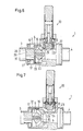
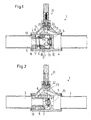
  • valve 1 and 2 show an axial valve 1 with a housing 2, which has an input 3 and an output 4. There is a between input 3 and output 4 Valve seat 5 arranged with which a valve element 6 interacts.
  • the valve element 6 has a hollow interior 7.
  • the interior 7 has a wall 8 with which the valve element 6 is guided on the outside on a guide 9 is fixed to the housing in the housing 2.
  • the valve element 6 is thus telescopically mounted on the guide.
  • the guide 9 is designed as an insert in the Housing 2 is fixed.
  • the valve element 6 has on the side that the output 4 is adjacent, a closed surface 10, the is surrounded by the seal 11, which is ultimately on Valve seat 5 comes to rest when the valve element 6 is in the position shown in Fig. 1.
  • the surface 10 stands over star-shaped webs 12 the wall 8 in connection. Are between the webs 12 Openings 13 formed through which fluid flow can that through the entrance 3 into the interior 7 of the Valve element 6 arrives when the valve element 6 from Valve seat 5 is raised, as shown in Fig. 2 is.
  • valve element 6 is also in a bore 14 of the housing, the inner diameter of which is practical is the same size as the outside diameter of the valve element 6. Between the valve element 6 and the housing 2 no seals are arranged. The valve element 6 is therefore seal-free and therefore low in friction the bore 14 out.
  • circumferential grooves 15 am Valve element 6 is indicated that between the valve element 6 and the bore 14 some play so that a "seepage path" 16 is formed, through the fluid through the interior 7 into an annular Can reach pressure chamber 17, which is limited by the guide 9, the valve element 6 and the housing 2.
  • the "seepage path” can also include a section the between the valve element 6 and the guide 9 in Area of the wall 8 is formed.
  • the guide 9 points thereby a thickened end 18 whose outer diameter is the same size as the inside diameter of the hole 14.
  • the concrete formation of the drainage path doesn't matter. You can also target openings or provide holes elsewhere, for example through the end 18 of the guide 9 to the To supply pressure chamber 17 with fluid.
  • a spring 19 is arranged in the pressure chamber 17 acts on the valve element 6 in the closing direction, the valve element 6 thus presses against the valve seat 5.
  • the pressure chamber 17 is connected to a via a channel 20 Pilot valve 21 in connection.
  • the pilot valve 21 has a pilot valve element 22 on that with a pilot valve seat 23 interacts.
  • the pilot valve seat 23 is connected to output 4 via a channel 24. It So it is a servo valve that with the help of Pilot valve 21 is activated by the same fluid, which is controlled by the axial valve 1. Thereby, that the valve element 6 is seal-free in the bore 14 of the housing 2 is guided, the friction during movement of the valve element is extremely low. Accordingly small forces and therefore low are sufficient Differential pressures across the valve element 6 to it move.
  • the axial valve 1 now works as follows:
  • Fluid that is fed through the inlet 3 arrives through the hollow guide 9 into the interior 7 of the valve element 6, but can not continue to flow because the valve element 6 with the seal 11 on the valve seat 5 is applied. Due to the increased pressure at inlet 3 the fluid penetrates through the soak path 16 to the pressure chamber 17 before and until pressure equalization exists between the inlet 3 and the pressure chamber 17. Due to the pressure in the pressure chamber 17, the valve element 6 acted upon in the closing direction. In addition, that will Valve element 6 by the force of the spring 19 in Closing direction applied. Ultimately it also works the pressure in input 3 is still on the face, which the Surface 10 bears in the closing direction. In the opening direction the pressure in the input also works through the Areas facing in the opening direction.
  • a flow path from inlet 3 is created for the fluid to the outlet 4, through the valve seat 5, more precisely through an opening 25 surrounded by valve seat 5 runs.
  • the flow path has a first section on in the interior 7 of the valve element 6 is formed, and a second section which is hollow Inside the guide 9 is formed. In the direction of flow seen the order of the two sections vice versa, of course.
  • the spring 19 is shown in FIG. 2 and the spring of the pilot valve 21 is omitted.
  • the pilot valve element 22 is lifted off the pilot valve seat 23.
  • valve element 6 is double in this embodiment performed, namely once on the guide 9 in the interior 7 and the other in the bore 14 in the housing 2. This makes it possible in a simple way to the annular To generate pressure chamber 17.
  • the seepage path 16 between the valve element 6 and the guide 9 trained.
  • the seepage path can also be formed at other points be, e.g. between the extension 26 and the inner wall of the inlet 3.
  • the valve element 6 has an extension 26 with which it is guided in the housing 2 and more precisely in the entrance 3.
  • the extension 26 points a reduced diameter. In other words has the valve element 6 in the region of the guide 9 Increase in diameter.
  • the extension 26 has an annular wall 27, with which the valve element 6 is guided in the input 3, the over three or more webs 28 with a central part 29 of the valve element 6 is connected. On the middle part 29 a closing element 30 is attached, which ultimately comes into contact with valve seat 5 when the valve element 6 is in the position shown in FIG. 6. Openings 31 are left between the webs 28, through the fluid from the entrance 3 into the interior 7 can reach.
  • pilot valve 20 in the illustration of FIG. 6 and 7, a closing spring of the pilot valve 20
  • the pilot valve element 22 lifts off Pilot valve seat 23 and the pressure chamber 17 comes over the channel 24 with the output 4 in connection.
  • the pressure in the pressure chamber 17 drops.
  • the pressure at input 3 works then in the opening direction to an area that is larger is the area in which the pressure at the entrance in Closing direction works. This can be, for example Surface 32, which starts from the extension 26.
  • the valve element 6 is thereby moved in the opening direction and the closing element 30 lifts off the valve seat 5. Thereby the opening 25 is released and the fluid can flow from input 3 to output 4.
  • FIGS. 1 and 2 points the housing 2 in the embodiment of FIGS. 6 and 7 a recess 33 in which the pilot valve element 22 is movable. At the foot of the recess 33 is then the pilot valve seat 23.
  • This configuration the advantage that on the one hand the overall height of the valve 1 decreased.
  • holes and additional channels in the housing 2 saved, for example the channel 20.
  • FIG. 8 shows a further embodiment of an axial valve, which essentially according to the embodiment Fig. 1 corresponds.
  • the same parts as in Fig. 1 are with provided with the same reference numerals.
  • valve element 6 not only in the area of the wall 8 of the Housing 2 guided on its outer circumference, but also on a tapered section 40, which is from a housing guide 41 is surrounded. Otherwise, the function and the structure of the axial valve 1 the same as in the Embodiment according to Fig. 1. Also here is the valve element 6 arranged without a seal in the housing bore 14, i.e. extraordinarily small differential pressures are sufficient between input 3 and output 4 to lift the valve element 6 from the valve seat 5, when the pilot valve 21 is opened.

Landscapes

  • Engineering & Computer Science (AREA)
  • General Engineering & Computer Science (AREA)
  • Mechanical Engineering (AREA)
  • Fluid-Driven Valves (AREA)

Abstract

Es wird ein Axialventil angegeben mit einem Gehäuse (2), einem Eingang (3), einem Ausgang (4), einem Ventilsitz (5) zwischen Eingang (3) und Ausgang (4) und einem mit dem Ventilsitz (5) zusammenwirkenden Ventilelement (6), das durch ein zwischen dem Eingang (3) und dem Ausgang (4) angeordnetes Pilotventil (20) gesteuert ist, wobei das Ventilelement (6) parallel zu einem Strömungspfad vom Eingang (3) zum Ausgang (4) bewegbar ist und einen Innenraum (7) umgibt. Man möchte bei unveränderten Außenabmessungen einen vergrößerten Durchfluß erreichen. Hierzu ist ein erster Abschnitt des Strömungspfads durch den Innenraum (7) geführt und ein Druckraum (17), in dem sich bei geschlossenem Pilotventil (20) ein auf das Ventilelement (6) wirkender Schließdruck bildet, ist zwischen dem Gehäuse (2) und dem Ventilelement (6) angeordnet. <IMAGE>

Description

Die Erfindung betrifft ein Axialventil mit einem Gehäuse, einem Eingang, einem Ausgang, einem Ventilsitz zwischen Eingang und Ausgang und einem mit dem Ventilsitz zusammenwirkenden Ventilelement, das durch ein zwischen dem Eingang und dem Ausgang angeordnetes Pilotventil gesteuert ist, wobei das Ventilelement parallel zu einem Strömungspfad vom Eingang zum Ausgang bewegbar ist und einen Innenraum umgibt.
Bei einem derartigen Axialventil, das von der Danfoss A/S, Nordborg, Dänemark, vertrieben wird, ist das Ventilelement in einem Käfig geführt, der zwischen dem Einlaß und dem Auslaß angeordnet ist. Das Ventilelement ist hohl. In dem Hohlraum ist eine Feder aufgenommen, die das Ventilelement in Axialrichtung aus dem Käfig herausdrückt und in Anlage an den Ventilsitz bringt. Wenn das Ventilelement vom Ventilsitz abgehoben wird, dann strömt das zu steuernde Fluid außen um den Käfig und außen um das Ventilelement herum, um durch den Ventilsitz zum Ausgang abzufließen.
Ein derartiges Ventil hat sich im Grunde bewährt. Allerdings ist eine Vergrößerung des Durchflusses nur beschränkt möglich, wenn man die Außenabmessungen beibehalten möchte.
Der Erfindung liegt die Aufgabe zugrunde, einen größeren Durchfluß bei unveränderten Außenabmessungen zu erreichen.
Diese Aufgabe wird bei einem Axialventil der eingangs genannten Art dadurch gelöst, daß ein erster Abschnitt des Strömungspfads durch den Innenraum geführt ist und ein Druckraum, in dem sich bei geschlossenem Pilotventil ein auf das Ventilelement wirkender Schließdruck bildet, zwischen dem Gehäuse und dem Ventilelement angeordnet ist.
Man ändert also den Strömungspfad für das Fluid. Das Fluid wird nicht mehr außen um das Ventilelement herumgeführt, sondern durch das Ventilelement hindurch. Wenn das Pilotventil geöffnet wird, werden Druckverhältnisse erzeugt, die zum Öffnen des Ventils, d.h. zum Abheben des Ventilelements vom Ventilsitz führen. Das Pilotventil steuert dabei das gleiche Fluid, das durch das Ventil an sich gesteuert werden soll. Dies vereinfacht die Bedienung des Ventils. Das Ventilelement wird in einer Gehäusebohrung geführt, d.h. man kann den Außendurchmesser des Ventilelements ganz erheblich vergrößern, so daß eine entsprechende Vergrößerung des Innenraums möglich ist. Die Vergrößerung des Innenraums stellt wiederum einen relativ großen Strömungsquerschnitt zur Verfügung, so daß das Ventil, wenn es geöffnet ist, einen nur ausgesprochen geringen Druckabfall erzeugt. Dadurch, daß der Druckraum zwischen dem Gehäuse und dem Ventilelement angeordnet ist, ist es möglich, das Ventilelement rotationssymmetrisch auszubilden. Dies vereinfacht die Fertigung. Die winkelmäßige Ausrichtung des Ventilelements zum Gehäuse muß nicht mehr überwacht werden.
Auch ist bevorzugt, daß das Ventilelement mit einer Wand des Innenraums auf einer Führung geführt ist, die einen zweiten Abschnitt des Strömungspfades umgibt. Damit hat der Hohlraum, der nun zum Ausbilden des Strömungspfades dient, eine zweite Aufgabe. Er dient nämlich gleichzeitig dazu, das Ventilelement auf der Führung zu führen. Damit ist es nicht mehr erforderlich, die Führung nach Art eines Käfigs in den Strömungsweg des Fluids zu legen. Man kann die Führung vielmehr freier ausgestalten.
Hierbei ist bevorzugt, daß die Führung gehäusefest angeordnet ist. Dies ergibt eine erhöhte Stabilität für die Führung des Ventilelements. Die Führung kann beispielsweise als Einsatz ausgebildet sein, der in ein Gehäuse des Ventils eingesetzt und dort fixiert ist.
Bevorzugterweise verläuft der Strömungspfad durch den Ventilsitz hindurch. Der Ventilsitz umgrenzt also, wie dies herkömmlicherweise bekannt ist, eine Öffnung, die als Abfluß für das Fluid dient, das durch das Ventil gesteuert wird. Der Ventilsitz bildet also keinen zusätzlichen Strömungswiderstand wie beispielsweise eine Platte, die mitten im Strömungsweg angeordnet und vom Fluid umströmt werden muß.
Vorzugsweise weist das Ventilelement an seiner dem Ventilsitz zugewandten Seite eine geschlossene Fläche auf. Diese Fläche verschließt dann die Öffnung, die vom Ventilsitz umschlossen ist. Dies vereinfacht die Steuerung und die Ausbildung des Ventilelements.
Vorzugsweise ist vorgesehen, daß das Ventilelement dichtungsfrei in einer Gehäusebohrung geführt ist. Die Kräfte, die man zum Bewegen des Ventilelements benötigt, werden klein gehalten. Man verzichtet nämlich auf eine Dichtung zwischen dem Ventilelement und dem Gehäuse. Ein Axialventil der infrage stehenden Art benötigt zum Öffnen einen Differenzdruck zwischen dem Eingang und dem Ausgang. Durch den Verzicht auf eine Dichtung zwischen dem Ventilelement und der Gehäusewand reichen nun sehr geringe Differenzdrücke aus, weil das Ventilelement praktisch reibungsfrei oder jedenfalls mit nur sehr geringen Reibungen im Gehäuse verlagert werden kann. Damit kann das Ventilelement auch dann bewegt werden, wenn der Differenzdruck zwischen Eingang und Ausgang nur sehr klein ist. Dies ist insbesondere bei Axialventilen von Vorteil, die mit Hilfe eines Pilotventils gesteuert werden, weil das Pilotventil die gleiche Flüssigkeit oder das gleiche Fluid steuert, das auch durch das Zusammenwirken zwischen dem Ventilelement und dem Ventilsitz gesteuert werden soll. Durch den Verzicht auf eine Dichtung zwischen dem Ventilelement und dem Gehäuse ergeben sich zwar kleinere Undichtigkeiten, die aber dadurch aufgefangen werden können, daß man eine Dichtung an anderer Stelle vorsieht, beispielsweise an der Stirnseite des Ventilelements. Im Endeffekt läßt sich also das Axialventil mit gleicher Dichtigkeit, aber verbesserten Eigenschaften dadurch bereitstellen, daß man die Strömung des Fluids durch das Ventilelement hindurch leitet.
Vorzugsweise ist das Pilotventil in einer Verbindung zwischen einem Druckraum, in dem ein in Schließrichtung auf das Ventil herrschender Druck herrscht, und dem Ausgang angeordnet. Wenn das Pilotventil öffnet, dann wird der Druck in dem Druckraum auf den Druck am Ausgang abgesenkt. Auf das Ventilelement wirkt dann in entgegengesetzter Richtung der Druck am Eingang, der das Ventilelement in Öffnungsrichtung bewegt. Dies ist eine relativ einfache Möglichkeit, das Ventilelement anzusteuern.
Bevorzugterweise ist der Druckraum über einen Sickerpfad mit Druck versorgt, der mit dem Innenraum in Verbindung steht. Der Sickerpfad kann zwar durch eine ausgeprägte Oberflächenstruktur zwischen dem Ventilelement und dem Gehäuse bzw. dem Ventilelement und der Führung gebildet werden. Dies ist aber in der Regel nicht notwendig. In den meisten Fällen läßt sich das Ventilelement nicht so spielfrei an das Gehäuse oder die Führung anpassen, daß die Anlage absolut dicht ist. Durch das Spiel zwischen dem Ventilelement und dem Gehäuse oder der Führung kann eine ausreichende Flüssigkeitsmenge in den Druckraum vordringen, die dann zum Schließen des Ventils dient. Da dieser Druckraum außen am Ventilelement angeordnet ist, steht eine relativ große Fläche zur Verfügung. Die Kraft, mit der das Ventilelement gegen den Ventilsitz gedrückt wird, steigt damit. Dies ergibt eine zuverlässige Ventilfunktion, weil das Ventil mit einer größeren Kraft schließt.
Vorzugsweise verkürzt sich der Sickerpfad beim Öffnen des Ventils. Dies erleichtert es, das Ventilelement in die Schließstellung zu bewegen. Man muß lediglich das Pilotventil schließen. Durch die kürzere Strecke des Sickerpfades, die bei der Öffnungsstellung des Ventilelements besteht, hat das Fluid einen geringeren Widerstand beim Durchtritt zum Druckraum zu erwarten. Der Druckraum füllt sich entsprechend schneller und bewegt dann das Ventilelement in die Schließstellung.
Vorzugsweise ist eine in Schließrichtung wirkende Feder im Druckraum angeordnet. Diese Feder unterstützt die Schließbewegung. Die Öffnungsbewegung wird durch den Druck am Eingang hervorgerufen, der entsprechend auf eine größere Fläche wirken muß. Hier zeigt sich erneut der Vorteil der erfindungsgemäßen Ausbildung des Ventilelements. Dadurch, daß das Ventilelement in seinem hohlen Innenraum geführt ist, kann der Druck am Eingang auf eine relativ große Fläche wirken und eine dementsprechend große Kraft erzeugen. Damit ist es möglich, eine wesentlich stärkere Feder als bisher zu verwenden, damit das Ventil fester schließt. Das Verwenden einer stärkeren Feder wird, wie gesagt, ermöglicht, weil die Druckkräfte beim Ventilelement auf eine Fläche mit größerem Durchmesser wirken. Eine stärkere Feder ergibt eine zuverlässigere Ventilfunktion.
In einer bevorzugten Ausgestaltung ist vorgesehen, daß die Führung auf der Einlaßseite des Ventilelements angeordnet ist. Das Fluid wird also durch die Führung in das Ventilelement hineingeführt. Damit werden Störungen beim Übergang von der Führung in das Ventilelement klein gehalten.
In einer alternativen Ausgestaltung ist vorgesehen, daß die Führung auf der Auslaßseite des Ventilelements angeordnet ist. In diesem Fall weist das Ventilelement zweckmäßigerweise ein ausgeprägtes Verschlußstück auf, das mit dem Ventilsitz zusammenwirkt. Die Führung umgibt dabei den Ventilsitz.
Vorzugsweise weist das Ventilelement im Bereich der Führung eine Durchmesservergrößerung auf. Diese Durchmesservergrößerung verbessert die Ausrichtung des Ventilelements zur Führung. Vor allem gewährleistet sie aber, daß relativ große Druckangriffsflächen in Öffnungs- und in Schließrichtung zur Verfügung stehen, so daß das Ventilelement mit ausreichend großen Kräften gegen den Ventilsitz gedrückt wird.
Schließlich ist von Vorteil, wenn das Gehäuse im Bereich des Pilotventils eine radial gerichtete Vertiefung aufweist. Das Pilotventil kann bei dieser Ausgestaltung in das Gehäuse hinein verlagert werden. Dadurch werden Bohrungen gespart.
Die Erfindung wird im folgenden anhand von bevorzugten Ausführungsbeispielen in Verbindung mit der Zeichnung näher beschrieben. Hierin zeigen:
Fig. 1
eine erste Ausführungsform eines Axialventils im geschlossenen Zustand,
Fig. 2
das Axialventil von Fig. 1 im geöffneten Zustand,
Fig. 3
ein Ventilelement des Ventils nach Fig. 1 und 2 in perspektivischer Darstellung,
Fig. 4
das Ventilelement im Längsschnitt IV-IV nach Fig. 5,
Fig. 5
eine Stirnseitenansicht des Ventilelements,
Fig. 6
eine zweite Ausführungsform eines Axialventils im geschlossenen Zustand,
Fig. 7
das Axialventil der Fig. 6 in geöffnetem Zustand und
Fig. 8
eine dritte Ausführungsform eines Axialventils im geschlossenen Zustand.
Die Fig. 1 und 2 zeigen ein Axialventil 1 mit einem Gehäuse 2, das einen Eingang 3 und einen Ausgang 4 aufweist. Zwischen dem Eingang 3 und dem Ausgang 4 ist ein Ventilsitz'5 angeordnet, mit dem ein Ventilelement 6 zusammenwirkt.
Das Ventilelement 6 weist einen hohlen Innenraum 7 auf. Der Innenraum 7 weist eine Wand 8 auf, mit der das Ventilelement 6 außen auf einer Führung 9 geführt ist, die gehäusefest im Gehäuse 2 angeordnet ist. Das Ventilelement 6 ist also teleskopierend auf der Führung gelagert. Die Führung 9 ist als Einsatz ausgebildet, der im Gehäuse 2 fixiert ist.
Das Ventilelement 6 weist an der Seite, die dem Ausgang 4 benachbart ist, eine geschlossene Fläche 10 auf, die von der Dichtung 11 umgeben ist, die letztendlich am Ventilsitz 5 zur Anlage kommt, wenn sich das Ventilelement 6 in der in Fig. 1 dargestellten Position befindet. Die Fläche 10 steht über sternförmige Stege 12 mit der Wand 8 in Verbindung. Zwischen den Stegen 12 sind Öffnungen 13 ausgebildet, durch die Fluid abfließen kann, das durch den Eingang 3 in den Innenraum 7 des Ventilelements 6 gelangt, wenn das Ventilelement 6 vom Ventilsitz 5 abgehoben ist, wie dies in Fig. 2 dargestellt ist.
Das Ventilelement 6 ist weiterhin in einer Bohrung 14 des Gehäuses geführt, deren Innendurchmesser praktisch genauso groß ist wie der Außendurchmesser des Ventilelements 6. Zwischen dem Ventilelement 6 und dem Gehäuse 2 sind keine Dichtungen angeordnet. Das Ventilelement 6 ist also dichtungsfrei und damit reibungsarm in der Bohrung 14 geführt. Durch umlaufende Nuten 15 am Ventilelement 6 ist angedeutet, daß zwischen dem Ventilelement 6 und der Bohrung 14 ein gewisses Spiel vorhanden ist, so daß ein "Sickerpfad" 16 gebildet ist, durch den Fluid durch den Innenraum 7 in einen ringförmigen Druckraum 17 gelangen kann, der begrenzt ist von der Führung 9, dem Ventilelement 6 und dem Gehäuse 2. Der "Sickerpfad" kann auch einen Abschnitt umfassen, der zwischen dem Ventilelement 6 und der Führung 9 im Bereich der Wand 8 gebildet ist. Die Führung 9 weist dabei ein verdicktes Ende 18 auf, dessen Außendurchmesser genauso groß ist wie der Innendurchmesser der Bohrung 14. Die konkrete Ausbildung des Sickerpfades spielt aber keine Rolle. Man kann auch gezielt Öffnungen oder Bohrungen an anderer Stelle vorsehen, beispielsweise durch das Ende 18 der Führung 9, um den Druckraum 17 mit Fluid zu versorgen.
In dem Druckraum 17 ist eine Feder 19 angeordnet, die das Ventilelement 6 in Schließrichtung beaufschlagt, das Ventilelement 6 also gegen den Ventilsitz 5 drückt.
Der Druckraum 17 steht über einen Kanal 20 mit einem Pilotventil 21 in Verbindung. Das Pilotventil 21 weist ein Pilotventilelement 22 auf, das mit einem Pilotventilsitz 23 zusammenwirkt. Der Pilotventilsitz 23 ist über einen Kanal 24 mit dem Ausgang 4 verbunden. Es handelt sich also um ein Servoventil, das mit Hilfe des Pilotventils 21 durch das gleiche Fluid aktiviert wird, das durch das Axialventil 1 gesteuert wird. Dadurch, daß das Ventilelement 6 dichtungsfrei in der Bohrung 14 des Gehäuses 2 geführt ist, ist die Reibung bei der Bewegung des Ventilelements außerordentlich gering. Dementsprechend reichen kleine Kräfte und damit geringe Differenzdrücke über das Ventilelement 6 aus, um es zu bewegen.
Das Axialventil 1 arbeitet nun wie folgt:
Fluid, das durch den Eingang 3 zugeführt wird, gelangt durch die hohle Führung 9 in den Innenraum 7 des Ventilelements 6, kann aber nicht weiter abfließen, weil das Ventilelement 6 mit der Dichtung 11 am Ventilsitz 5 anliegt. Aufgrund des erhöhten Drucks am Eingang 3 dringt das Fluid durch den Sickerpfad 16 bis zum Druckraum 17 vor und zwar solange, bis ein Druckausgleich zwischen dem Eingang 3 und dem Druckraum 17 besteht. Durch den Druck im Druckraum 17 wird das Ventilelement 6 in Schließrichtung beaufschlagt. Zusätzlich wird das Ventilelement 6 durch die Kraft der Feder 19 in Schließrichtung beaufschlagt. Letztendlich wirkt auch der Druck im Eingang 3 noch auf die Stirnseite, die die Fläche 10 trägt, in Schließrichtung. In Öffnungsrichtung wirkt der Druck im Eingang auch und zwar über die in Öffnungsrichtung gerichteten Flächen. Dies ist im wesentlichen die Stärke der Ringwand des Ventilelements 6 plus die Flächen der Stege 12. Hierbei sind die in die eine und in die andere Richtung beaufschlagten Flächen so aufeinander abgestimmt, daß das Ventilelement 6 dann in Schließstellung bleibt, wenn im Druckraum 17 der Druck am Eingang 3 herrscht.
Wenn nun das Pilotventil 21 öffnet, entweicht der Druck aus dem Druckraum 17. Im Druckraum 17 herrscht dann praktisch der Druck am Ausgang 4. Der Druck am Eingang 3 ist dann in der Lage, das Ventilelement 6 vom Ventilsitz 5 abzuheben und in die in Fig. 2 dargestellte Position zu verschieben. Das Axialventil 1 ist damit geöffnet.
Für das Fluid entsteht ein Strömungspfad vom Eingang 3 zum Ausgang 4, der durch den Ventilsitz 5, genauer gesagt durch eine vom Ventilsitz 5 umgebene Öffnung 25 verläuft. Der Strömungspfad weist einen ersten Abschnitt auf, der im Innenraum 7 des Ventilelements 6 gebildet ist, und einen zweiten Abschnitt, der im hohlen Inneren der Führung 9 gebildet ist. In Strömungsrichtung gesehen ist die Reihenfolge der beiden Abschnitte natürlich umgekehrt.
Aus Gründen der Übersicht sind in Fig. 2 die Feder 19 und die Feder des Pilotventils 21 weggelassen. Das Pilotventilelement 22 ist vom Pilotventilsitz 23 abgehoben.
Das Ventilelement 6 ist bei dieser Ausgestaltung zweifach geführt, nämlich einmal auf der Führung 9 im Innenraum 7 und zum anderen in der Bohrung 14 im Gehäuse 2. Dadurch ist es auf einfache Weise möglich, den ringförmigen Druckraum 17 zu erzeugen.
Die Fig: 6 und 7 zeigen eine alternative Ausgestaltung, bei der gleiche und einander entsprechende Teile mit den gleichen Bezugszeichen versehen sind.
Während bei der Ausgestaltung nach Fig. 1 und 2 die Führung 9 in Strömungsrichtung vom Eingang 3 zum Ausgang 4 vor dem Ventilelement 6 angeordnet ist, befindet sich die Führung 9 nun in Strömungsrichtung hinter dem Ventilelement 6. Die Führung beinhaltet in diesem Fall den Ventilsitz 5, der bei der Ausgestaltung nach Fig. 1 und 2 noch Bestandteil des Gehäuses ist, aber auch dort in einem Einsatz ausgebildet sein kann.
Hier ist der Sickerpfad 16 zwischen dem Ventilelement 6 und der Führung 9 ausgebildet. Wie oben ausgeführt, kann der Sickerpfad auch an anderen Stellen ausgebildet sein, z.B. zwischen dem Fortsatz 26 und der Innenwand des Eingangs 3. Das Ventilelement 6 weist einen Fortsatz 26 auf, mit dem es im Gehäuse 2 geführt ist und zwar genauer gesagt im Eingang 3. Der Fortsatz 26 weist einen verminderten Durchmesser auf. Mit anderen Worten weist das Ventilelement 6 im Bereich der Führung 9 eine Durchmesservergrößerung auf.
Der Fortsatz 26 weist eine ringförmige Wand 27 auf, mit der das Ventilelement 6 im Eingang 3 geführt ist, die über drei oder mehr Stege 28 mit einem Mittelteil 29 des Ventilelements 6 verbunden ist. Am Mittelteil 29 ist ein Schließelement 30 befestigt, das letztendlich am Ventilsitz 5 zur Anlage kommt, wenn das Ventilelement 6 sich in der in Fig. 6 dargestellten Position befindet. Zwischen den Stegen 28 sind Öffnungen 31 freigelassen, durch die Fluid aus dem Eingang 3 in den Innenraum 7 gelangen kann.
Fluid, das vom Eingang 3 über die Öffnungen 31 in den Innenraum 7 gelangt, dringt durch den Sickerpfad 16 in den Druckraum 17 vor und übt damit eine Schließkraft auf das Ventilelement 6 aus, die das Ventilelement 6 in die in Fig. 6 dargestellte Position drückt. Unterstützend wirken hierbei die Kraft der Feder 7 und der Druck des durch den Eingang 3 austretenden Fluids.
Wenn das Pilotventil 20 (bei der Darstellung der Fig. 6 und 7 fehlt eine Schließfeder des Pilotventils 20) geöffnet wird, dann hebt das Pilotventilelement 22 vom Pilotventilsitz 23 ab und der Druckraum 17 kommt über den Kanal 24 mit dem Ausgang 4 in Verbindung. Der Druck im Druckraum 17 sinkt. Der Druck am Eingang 3 wirkt dann in Öffnungsrichtung auf eine Fläche, die größer ist als die Fläche, in der der Druck am Eingang in Schließrichtung wirkt. Dies kann beispielsweise eine Fläche 32 sein, die vom Fortsatz 26 ausgeht. Das Ventilelement 6 wird dadurch in Öffnungsrichtung bewegt und das Schließelement 30 hebt vom Ventilsitz 5 ab. Dadurch wird die Öffnung 25 freigegeben und das Fluid kann vom Eingang 3 zum Ausgang 4 strömen.
Wenn das Pilotventil 20 geschlossen wird, dann kann sich im Druckraum 17 wiederum ein Druck aufbauen. Der Druckaufbau kann im Falle eines geöffneten Ventilelements 6 relativ schnell erfolgen, weil der Sickerpfad 16 hier gegenüber der geschlossenen Stellung des Ventilelements 6 verkürzt ist, wie ein Vergleich der Fig. 6 und 7 zeigt. Das Ventilelement 6 wird also relativ schnell in Schließrichtung bewegt, wodurch das Schließelement 30 zur Anlage an dem Ventilsitz 5 gelangt.
Im Gegensatz zu der Ausbildung der Fig. 1 und 2 weist das Gehäuse 2 bei der Ausführungsform der Fig. 6 und 7 eine Vertiefung 33 auf, in der das Pilotventilelement 22 bewegbar ist. Am Fuß der Vertiefung 33 befindet sich dann der Pilotventilsitz 23. Diese Ausgestaltung hat den Vorteil, daß sich einerseits die Bauhöhe des Ventils 1 vermindert. Andererseits werden Bohrungen und zusätzliche Kanäle im Gehäuse 2 gespart, beispielsweise der Kanal 20.
Fig. 8 zeigt eine weitere Ausführungsform eines Axialventils, die im wesentlichen der Ausführungsform nach Fig. 1 entspricht. Gleiche Teile wie in Fig. 1 sind mit den gleichen Bezugszeichen versehen.
Im Unterschied zu der Ausführungsform nach Fig. 1 ist das Ventilelement 6 nicht nur im Bereich der Wand 8 des Gehäuses 2 an seinem Außenumfang geführt, sondern auch an einem verjüngten Abschnitt 40, der von einer Gehäuseführung 41 umgeben ist. Im übrigen ist die Funktion und der Aufbau des Axialventils 1 gleich wie bei der Ausführungsform nach Fig. 1. Auch hier ist das Ventilelement 6 dichtungsfrei in der Gehäusebohrung 14 angeordnet, d.h. es reichen außerordentlich kleine Differenzdrücke zwischen dem Eingang 3 und dem Ausgang 4 aus, um das Ventilelement 6 vom Ventilsitz 5 abzuheben, wenn das Pilotventil 21 geöffnet wird.
Claims (14)

  1. Axialventil mit einem Gehäuse, einem Eingang, einem Ausgang, einem Ventilsitz zwischen Eingang und Ausgang und einem mit dem Ventilsitz zusammenwirkenden Ventilelement, das durch ein zwischen dem Eingang und dem Ausgang angeordnetes Pilotventil gesteuert ist, wobei das Ventilelement parallel zu einem Strömungspfad vom Eingang zum Ausgang bewegbar ist und einen Innenraum umgibt, dadurch gekennzeichnet, daß ein erster Abschnitt des Strömungspfads durch den Innenraum (7) geführt ist und ein Druckraum (17), in dem sich bei geschlossenem Pilotventil (20) ein auf das Ventilelement (6) wirkender Schließdruck bildet, zwischen dem Gehäuse (2) und dem Ventilelement (6) angeordnet ist.
  2. Ventil nach Anspruch 1, dadurch gekennzeichnet, daß das Ventilelement (6) mit einer Wand (8) des Innenraums (7) auf einer Führung (9) geführt ist, die einen zweiten Abschnitt des Strömungspfades umgibt.
  3. Ventil nach Anspruch 2, dadurch gekennzeichnet, daß die Führung (9) gehäusefest angeordnet ist.
  4. Ventil nach einem der Ansprüche 1 bis 3, dadurch gekennzeichnet, daß der Strömungspfad durch den Ventilsitz (5) hindurch verläuft.
  5. Ventil nach einem der Ansprüche 1 bis 4, dadurch gekennzeichnet, daß das Ventilelement (6) an seiner dem Ventilsitz (5) zugewandten Seite eine geschlossene Fläche (10) aufweist.
  6. Ventil nach einem der Ansprüche 1 bis 5, dadurch gekennzeichnet, daß das Ventilelement (6) dichtungsfrei in einer Gehäusebohrung (3, 14) geführt ist.
  7. Ventil nach einem der Ansprüche 1 bis 6, dadurch gekennzeichnet, daß das Pilotventil (21) in einer Verbindung zwischen einem Druckraum (17), in dem ein in Schließrichtung auf das Ventilelement (6) herrschender Druck herrscht, und dem Ausgang (4) angeordnet ist.
  8. Ventil nach Anspruch 7, dadurch gekennzeichnet, daß der Druckraum (17) über einen Sickerpfad (16) mit Druck versorgt ist, der mit dem Innenraum (7) in Verbindung steht.
  9. Ventil nach Anspruch 8, dadurch gekennzeichnet, daß sich der Sickerpfad (16) beim Öffnen des Ventils verkürzt.
  10. Ventil nach einem der Ansprüche 7 bis 9, dadurch gekennzeichnet, daß eine in Schließrichtung wirkende Feder (19) im Druckraum (17) angeordnet ist.
  11. Ventil nach einem der Ansprüche 2 bis 10, dadurch gekennzeichnet, daß die Führung (9) auf der Einlaßseite des Ventilelements (6) angeordnet ist.
  12. Ventil nach einem der Ansprüche 2 bis 10, dadurch gekennzeichnet, daß die Führung (9) auf der Auslaßseite des Ventilelements (6) angeordnet ist.
  13. Ventil nach Anspruch 12, dadurch gekennzeichnet, daß das Ventilelement (6) im Bereich der Führung (9) eine Durchmesservergrößerung aufweist.
  14. Ventil nach Anspruch 12 oder 13, dadurch gekennzeichnet, daß das Gehäuse (2) im Bereich des Pilotventils (21) eine radial gerichtete Vertiefung (33) aufweist.
EP03078347A 2002-10-31 2003-10-23 Axialventil Withdrawn EP1416208A1 (de)

Applications Claiming Priority (2)

Application Number Priority Date Filing Date Title
DE10251167 2002-10-31
DE10251167A DE10251167B4 (de) 2002-10-31 2002-10-31 Axialventil

Publications (1)

Publication Number Publication Date
EP1416208A1 true EP1416208A1 (de) 2004-05-06

Family

ID=32087331

Family Applications (1)

Application Number Title Priority Date Filing Date
EP03078347A Withdrawn EP1416208A1 (de) 2002-10-31 2003-10-23 Axialventil

Country Status (3)

Country Link
US (1) US6955331B2 (de)
EP (1) EP1416208A1 (de)
DE (1) DE10251167B4 (de)

Cited By (2)

* Cited by examiner, † Cited by third party
Publication number Priority date Publication date Assignee Title
FR2976328A1 (fr) * 2011-06-08 2012-12-14 Pons R Dispositif de regulation en temps reel d'un flux de fluide sous pression
EP3106726A1 (de) 2015-06-15 2016-12-21 Danfoss A/S Axialventil

Families Citing this family (7)

* Cited by examiner, † Cited by third party
Publication number Priority date Publication date Assignee Title
DK2166423T3 (en) * 2008-09-19 2018-03-12 Isomatic As Balanced fluid valve
US8336849B2 (en) * 2010-02-11 2012-12-25 The United States Of America As Represented By The Administrator Of The National Aeronautics And Space Administration Conical seat shut off valve
US9435449B2 (en) * 2012-04-05 2016-09-06 The Boeing Company Pilot valve controlled positive and negative pressure relief valves
JP2015224649A (ja) * 2014-05-26 2015-12-14 株式会社不二工機 二段パイロット式電磁弁
WO2019079426A1 (en) * 2017-10-17 2019-04-25 Automotive Technologies International, Inc. HIGH SPEED VALVE
EP3712434B1 (de) 2019-03-20 2021-12-22 Danfoss A/S Rückschlagventildämpfung
WO2026073984A1 (en) * 2024-10-04 2026-04-09 Danfoss A/S Axial flow control valve with annular discharge outlet into main fluid passage for fluid discharged from pilot valve

Citations (5)

* Cited by examiner, † Cited by third party
Publication number Priority date Publication date Assignee Title
US2799466A (en) * 1956-04-09 1957-07-16 Frederick R Hickerson Solenoid pilot controlled piston valve
US2921768A (en) * 1957-05-28 1960-01-19 Actuation Res Corp Differential pressure energized pilot valve controlled shut-off valve with fluid pressure actuator seal
US4194694A (en) * 1977-03-03 1980-03-25 Hickerson Frederick R Fluid control valve
US4651768A (en) * 1985-05-25 1987-03-24 Alfred Epe Servovalve for pipe flange connection
WO1995023309A1 (en) * 1994-02-23 1995-08-31 Reinhard Otto Koenig In-line valve controlled by pilot operated pressure chamber behind the valve member

Family Cites Families (28)

* Cited by examiner, † Cited by third party
Publication number Priority date Publication date Assignee Title
US2921466A (en) 1957-10-31 1960-01-19 Magnaflux Corp Sonic thickness measuring apparatus
US2919714A (en) * 1958-01-03 1960-01-05 United Aircraft Corp Pressure balanced regulating and shut-off valve
GB1243054A (en) * 1968-01-22 1971-08-18 Rotax Ltd Fluid flow controlling valves
US3540462A (en) * 1968-08-02 1970-11-17 Avco Corp Miniaturized flow control valve
US3981479A (en) 1974-06-14 1976-09-21 Snap-Tite, Inc. Check valve
US4082148A (en) * 1976-07-26 1978-04-04 A-T-O Inc. Fire protection system
US4073464A (en) * 1976-08-24 1978-02-14 Chemetron Corporation Cylinder valve for gas fire extinguishing system
GB1546022A (en) 1977-02-25 1979-05-16 Coal Ind Fluid operable valves
FR2390655A1 (fr) * 1977-05-13 1978-12-08 Fm Ind Vanne tubulaire pilotee
US4201362A (en) * 1978-06-30 1980-05-06 Kabushiki Kaisha Saginomiya Seisakusho Electromagnetic pilot type valve
FR2506888A1 (fr) 1981-06-01 1982-12-03 Alsthom Atlantique Vanne d'arret a fermeture rapide
DE3315972A1 (de) * 1983-05-02 1984-11-08 Automatic Switch Co., Florham Park, N. J. Ventil
DE3409973A1 (de) 1984-03-19 1985-09-26 Cameron Iron Works Gmbh, 3100 Celle Drosselorgan zur herabsetzung des drucks in foerderleitungen
EP0230849A1 (de) 1986-01-29 1987-08-05 MANNESMANN Aktiengesellschaft Regelventil/Absperrventil
EP0253064A3 (de) * 1986-07-08 1988-10-26 AVS Ing. J.C. Römer GmbH Membranventil für Fluide
US4671485A (en) 1986-07-24 1987-06-09 Richdel Div. Of Garden America Corp. Solenoid-operated pilot valve with adjustable flow control
DD253461A1 (de) * 1986-10-23 1988-01-20 Prenzlau Maw Armaturenwerk Mediengesteuertes, koaxial durchstroemtes regelventil
DE3814519A1 (de) 1988-04-29 1989-11-09 Danfoss As Temperaturabhaengiges ventil
JP2742792B2 (ja) * 1988-06-28 1998-04-22 清原 まさ子 電磁制御装置
CH688833A5 (de) 1993-05-19 1998-04-15 Fischer Georg Rohrleitung Ventil.
EP0727600A1 (de) 1995-02-15 1996-08-21 Georg Fischer Rohrleitungssysteme AG Membranventil
US6303238B1 (en) * 1997-12-01 2001-10-16 The Trustees Of Princeton University OLEDs doped with phosphorescent compounds
US6029720A (en) 1998-06-29 2000-02-29 Swinford; Mark D. Dispensing tool assembly for evacuating and charging a fluid system
DE19901253B4 (de) * 1999-01-15 2006-02-23 müller co-ax ag Koaxialventil mit Strangpreßprofil als Gehäusekörper
US6039073A (en) 1999-03-02 2000-03-21 International Valve Corporation Check valve
US6821645B2 (en) * 1999-12-27 2004-11-23 Fuji Photo Film Co., Ltd. Light-emitting material comprising orthometalated iridium complex, light-emitting device, high efficiency red light-emitting device, and novel iridium complex
US6670645B2 (en) * 2000-06-30 2003-12-30 E. I. Du Pont De Nemours And Company Electroluminescent iridium compounds with fluorinated phenylpyridines, phenylpyrimidines, and phenylquinolines and devices made with such compounds
AT4708U1 (de) * 2000-11-15 2001-10-25 Hermeling Werner Dipl Ing Axial durchströmtes hochdruckschieberventil

Patent Citations (5)

* Cited by examiner, † Cited by third party
Publication number Priority date Publication date Assignee Title
US2799466A (en) * 1956-04-09 1957-07-16 Frederick R Hickerson Solenoid pilot controlled piston valve
US2921768A (en) * 1957-05-28 1960-01-19 Actuation Res Corp Differential pressure energized pilot valve controlled shut-off valve with fluid pressure actuator seal
US4194694A (en) * 1977-03-03 1980-03-25 Hickerson Frederick R Fluid control valve
US4651768A (en) * 1985-05-25 1987-03-24 Alfred Epe Servovalve for pipe flange connection
WO1995023309A1 (en) * 1994-02-23 1995-08-31 Reinhard Otto Koenig In-line valve controlled by pilot operated pressure chamber behind the valve member

Cited By (3)

* Cited by examiner, † Cited by third party
Publication number Priority date Publication date Assignee Title
FR2976328A1 (fr) * 2011-06-08 2012-12-14 Pons R Dispositif de regulation en temps reel d'un flux de fluide sous pression
EP3106726A1 (de) 2015-06-15 2016-12-21 Danfoss A/S Axialventil
WO2016202635A1 (en) 2015-06-15 2016-12-22 Danfoss A/S Axial valve

Also Published As

Publication number Publication date
DE10251167A1 (de) 2004-05-19
US20040084646A1 (en) 2004-05-06
US6955331B2 (en) 2005-10-18
DE10251167B4 (de) 2004-10-14

Similar Documents

Publication Publication Date Title
DE4327825C2 (de) Drosselrückschlagelement
DE69708991T2 (de) Wechselventil mit Mitteln zur Vermeidung von Gegenstrom
DE102014017801B4 (de) Druckbegrenzungsventil
EP1431496A2 (de) Elektrohydraulischer Servotürantrieb zum Antrieb einer Tür, eines Fensters oder dergleichen
DE2104039C2 (de) Schieberventil als Steuerventil zur Druckmittelversorgung eines hydraulischen Servomotors
DE10324307B3 (de) Schnellkupplungseinheit mit integriertem Rückschlagventil
EP1416208A1 (de) Axialventil
DE3507866C2 (de)
EP0121600A1 (de) Steuerventil
DE2750502A1 (de) Hydraulikventil
DE19932139B4 (de) Vorgesteuertes Schieberventil
DE3206555A1 (de) 3/2-wegeventil
DE102023101360A1 (de) Ventil mit Arretierung
EP0195389B2 (de) Rohrtrenner
DE102011015781A1 (de) Drosselventil
EP1317638A1 (de) Wegeventil
DE19633539C2 (de) Druckabschaltventil
WO2002066873A1 (de) Vorgesteuertes 2/2 wege-sitzventil
DE2753619C2 (de)
DD245937A1 (de) Ventil
EP1258662A2 (de) Vorrichtung zum Absperren von von Fluiden durchströmten Rohrleitungen mittels eines kugelförmigen Verschlusskörper
DD150008B1 (de) Selbstschliessendes absperrventil fuer hohe druecke
DE10341356B4 (de) Vorspannventil mit zumindest zwei Schaltstufen sowie hydraulische Betätigungsanordnung
DE202017003786U1 (de) Ventilanordnung und Ventilbaugruppe
DE1953955C3 (de) Schnell öffnendes Schaltventil

Legal Events

Date Code Title Description
PUAI Public reference made under article 153(3) epc to a published international application that has entered the european phase

Free format text: ORIGINAL CODE: 0009012

AK Designated contracting states

Kind code of ref document: A1

Designated state(s): AT BE BG CH CY CZ DE DK EE ES FI FR GB GR HU IE IT LI LU MC NL PT RO SE SI SK TR

AX Request for extension of the european patent

Extension state: AL LT LV MK

17P Request for examination filed

Effective date: 20040609

17Q First examination report despatched

Effective date: 20040802

AKX Designation fees paid

Designated state(s): AT BE BG CH CY CZ DE DK EE ES FI FR GB GR HU IE IT LI LU MC NL PT RO SE SI SK TR

STAA Information on the status of an ep patent application or granted ep patent

Free format text: STATUS: THE APPLICATION IS DEEMED TO BE WITHDRAWN

18D Application deemed to be withdrawn

Effective date: 20050923