EP1416163A2 - Kreiselpumpe mit Auswaschung der Fugenspalte - Google Patents
Kreiselpumpe mit Auswaschung der Fugenspalte Download PDFInfo
- Publication number
- EP1416163A2 EP1416163A2 EP03090441A EP03090441A EP1416163A2 EP 1416163 A2 EP1416163 A2 EP 1416163A2 EP 03090441 A EP03090441 A EP 03090441A EP 03090441 A EP03090441 A EP 03090441A EP 1416163 A2 EP1416163 A2 EP 1416163A2
- Authority
- EP
- European Patent Office
- Prior art keywords
- fluid
- conveying part
- axial
- rotor
- hub
- Prior art date
- Legal status (The legal status is an assumption and is not a legal conclusion. Google has not performed a legal analysis and makes no representation as to the accuracy of the status listed.)
- Granted
Links
Images



Classifications
-
- F—MECHANICAL ENGINEERING; LIGHTING; HEATING; WEAPONS; BLASTING
- F16—ENGINEERING ELEMENTS AND UNITS; GENERAL MEASURES FOR PRODUCING AND MAINTAINING EFFECTIVE FUNCTIONING OF MACHINES OR INSTALLATIONS; THERMAL INSULATION IN GENERAL
- F16C—SHAFTS; FLEXIBLE SHAFTS; ELEMENTS OR CRANKSHAFT MECHANISMS; ROTARY BODIES OTHER THAN GEARING ELEMENTS; BEARINGS
- F16C32/00—Bearings not otherwise provided for
- F16C32/04—Bearings not otherwise provided for using magnetic or electric supporting means
- F16C32/0406—Magnetic bearings
- F16C32/044—Active magnetic bearings
-
- A—HUMAN NECESSITIES
- A61—MEDICAL OR VETERINARY SCIENCE; HYGIENE
- A61M—DEVICES FOR INTRODUCING MEDIA INTO, OR ONTO, THE BODY; DEVICES FOR TRANSDUCING BODY MEDIA OR FOR TAKING MEDIA FROM THE BODY; DEVICES FOR PRODUCING OR ENDING SLEEP OR STUPOR
- A61M60/00—Blood pumps; Devices for mechanical circulatory actuation; Balloon pumps for circulatory assistance
- A61M60/10—Location thereof with respect to the patient's body
- A61M60/122—Implantable pumps or pumping devices, i.e. the blood being pumped inside the patient's body
- A61M60/165—Implantable pumps or pumping devices, i.e. the blood being pumped inside the patient's body implantable in, on, or around the heart
- A61M60/178—Implantable pumps or pumping devices, i.e. the blood being pumped inside the patient's body implantable in, on, or around the heart drawing blood from a ventricle and returning the blood to the arterial system via a cannula external to the ventricle, e.g. left or right ventricular assist devices
-
- A—HUMAN NECESSITIES
- A61—MEDICAL OR VETERINARY SCIENCE; HYGIENE
- A61M—DEVICES FOR INTRODUCING MEDIA INTO, OR ONTO, THE BODY; DEVICES FOR TRANSDUCING BODY MEDIA OR FOR TAKING MEDIA FROM THE BODY; DEVICES FOR PRODUCING OR ENDING SLEEP OR STUPOR
- A61M60/00—Blood pumps; Devices for mechanical circulatory actuation; Balloon pumps for circulatory assistance
- A61M60/20—Type thereof
- A61M60/205—Non-positive displacement blood pumps
- A61M60/216—Non-positive displacement blood pumps including a rotating member acting on the blood, e.g. impeller
- A61M60/237—Non-positive displacement blood pumps including a rotating member acting on the blood, e.g. impeller the blood flow through the rotating member having mainly axial components, e.g. axial flow pumps
-
- A—HUMAN NECESSITIES
- A61—MEDICAL OR VETERINARY SCIENCE; HYGIENE
- A61M—DEVICES FOR INTRODUCING MEDIA INTO, OR ONTO, THE BODY; DEVICES FOR TRANSDUCING BODY MEDIA OR FOR TAKING MEDIA FROM THE BODY; DEVICES FOR PRODUCING OR ENDING SLEEP OR STUPOR
- A61M60/00—Blood pumps; Devices for mechanical circulatory actuation; Balloon pumps for circulatory assistance
- A61M60/40—Details relating to driving
- A61M60/403—Details relating to driving for non-positive displacement blood pumps
- A61M60/422—Details relating to driving for non-positive displacement blood pumps the force acting on the blood contacting member being electromagnetic, e.g. using canned motor pumps
-
- A—HUMAN NECESSITIES
- A61—MEDICAL OR VETERINARY SCIENCE; HYGIENE
- A61M—DEVICES FOR INTRODUCING MEDIA INTO, OR ONTO, THE BODY; DEVICES FOR TRANSDUCING BODY MEDIA OR FOR TAKING MEDIA FROM THE BODY; DEVICES FOR PRODUCING OR ENDING SLEEP OR STUPOR
- A61M60/00—Blood pumps; Devices for mechanical circulatory actuation; Balloon pumps for circulatory assistance
- A61M60/50—Details relating to control
- A61M60/508—Electronic control means, e.g. for feedback regulation
- A61M60/538—Regulation using real-time blood pump operational parameter data, e.g. motor current
-
- A—HUMAN NECESSITIES
- A61—MEDICAL OR VETERINARY SCIENCE; HYGIENE
- A61M—DEVICES FOR INTRODUCING MEDIA INTO, OR ONTO, THE BODY; DEVICES FOR TRANSDUCING BODY MEDIA OR FOR TAKING MEDIA FROM THE BODY; DEVICES FOR PRODUCING OR ENDING SLEEP OR STUPOR
- A61M60/00—Blood pumps; Devices for mechanical circulatory actuation; Balloon pumps for circulatory assistance
- A61M60/80—Constructional details other than related to driving
- A61M60/802—Constructional details other than related to driving of non-positive displacement blood pumps
- A61M60/81—Pump housings
- A61M60/812—Vanes or blades, e.g. static flow guides
-
- A—HUMAN NECESSITIES
- A61—MEDICAL OR VETERINARY SCIENCE; HYGIENE
- A61M—DEVICES FOR INTRODUCING MEDIA INTO, OR ONTO, THE BODY; DEVICES FOR TRANSDUCING BODY MEDIA OR FOR TAKING MEDIA FROM THE BODY; DEVICES FOR PRODUCING OR ENDING SLEEP OR STUPOR
- A61M60/00—Blood pumps; Devices for mechanical circulatory actuation; Balloon pumps for circulatory assistance
- A61M60/80—Constructional details other than related to driving
- A61M60/802—Constructional details other than related to driving of non-positive displacement blood pumps
- A61M60/818—Bearings
- A61M60/82—Magnetic bearings
- A61M60/822—Magnetic bearings specially adapted for being actively controlled
-
- F—MECHANICAL ENGINEERING; LIGHTING; HEATING; WEAPONS; BLASTING
- F04—POSITIVE - DISPLACEMENT MACHINES FOR LIQUIDS; PUMPS FOR LIQUIDS OR ELASTIC FLUIDS
- F04D—NON-POSITIVE-DISPLACEMENT PUMPS
- F04D13/00—Pumping installations or systems
- F04D13/02—Units comprising pumps and their driving means
- F04D13/06—Units comprising pumps and their driving means the pump being electrically driven
- F04D13/0606—Canned motor pumps
- F04D13/0633—Details of the bearings
-
- F—MECHANICAL ENGINEERING; LIGHTING; HEATING; WEAPONS; BLASTING
- F04—POSITIVE - DISPLACEMENT MACHINES FOR LIQUIDS; PUMPS FOR LIQUIDS OR ELASTIC FLUIDS
- F04D—NON-POSITIVE-DISPLACEMENT PUMPS
- F04D13/00—Pumping installations or systems
- F04D13/02—Units comprising pumps and their driving means
- F04D13/06—Units comprising pumps and their driving means the pump being electrically driven
- F04D13/0606—Canned motor pumps
- F04D13/064—Details of the magnetic circuit
-
- F—MECHANICAL ENGINEERING; LIGHTING; HEATING; WEAPONS; BLASTING
- F04—POSITIVE - DISPLACEMENT MACHINES FOR LIQUIDS; PUMPS FOR LIQUIDS OR ELASTIC FLUIDS
- F04D—NON-POSITIVE-DISPLACEMENT PUMPS
- F04D13/00—Pumping installations or systems
- F04D13/02—Units comprising pumps and their driving means
- F04D13/06—Units comprising pumps and their driving means the pump being electrically driven
- F04D13/0646—Units comprising pumps and their driving means the pump being electrically driven the hollow pump or motor shaft being the conduit for the working fluid
-
- F—MECHANICAL ENGINEERING; LIGHTING; HEATING; WEAPONS; BLASTING
- F04—POSITIVE - DISPLACEMENT MACHINES FOR LIQUIDS; PUMPS FOR LIQUIDS OR ELASTIC FLUIDS
- F04D—NON-POSITIVE-DISPLACEMENT PUMPS
- F04D15/00—Control, e.g. regulation, of pumps, pumping installations or systems
-
- F—MECHANICAL ENGINEERING; LIGHTING; HEATING; WEAPONS; BLASTING
- F04—POSITIVE - DISPLACEMENT MACHINES FOR LIQUIDS; PUMPS FOR LIQUIDS OR ELASTIC FLUIDS
- F04D—NON-POSITIVE-DISPLACEMENT PUMPS
- F04D29/00—Details, component parts, or accessories
- F04D29/04—Shafts or bearings, or assemblies thereof
- F04D29/041—Axial thrust balancing
- F04D29/0413—Axial thrust balancing hydrostatic; hydrodynamic thrust bearings
-
- F—MECHANICAL ENGINEERING; LIGHTING; HEATING; WEAPONS; BLASTING
- F04—POSITIVE - DISPLACEMENT MACHINES FOR LIQUIDS; PUMPS FOR LIQUIDS OR ELASTIC FLUIDS
- F04D—NON-POSITIVE-DISPLACEMENT PUMPS
- F04D3/00—Axial-flow pumps
- F04D3/02—Axial-flow pumps of screw type
-
- F—MECHANICAL ENGINEERING; LIGHTING; HEATING; WEAPONS; BLASTING
- F16—ENGINEERING ELEMENTS AND UNITS; GENERAL MEASURES FOR PRODUCING AND MAINTAINING EFFECTIVE FUNCTIONING OF MACHINES OR INSTALLATIONS; THERMAL INSULATION IN GENERAL
- F16C—SHAFTS; FLEXIBLE SHAFTS; ELEMENTS OR CRANKSHAFT MECHANISMS; ROTARY BODIES OTHER THAN GEARING ELEMENTS; BEARINGS
- F16C39/00—Relieving load on bearings
- F16C39/06—Relieving load on bearings using magnetic means
- F16C39/063—Permanent magnets
-
- H—ELECTRICITY
- H02—GENERATION; CONVERSION OR DISTRIBUTION OF ELECTRIC POWER
- H02K—DYNAMO-ELECTRIC MACHINES
- H02K11/00—Structural association of dynamo-electric machines with electric components or with devices for shielding, monitoring or protection
- H02K11/20—Structural association of dynamo-electric machines with electric components or with devices for shielding, monitoring or protection for measuring, monitoring, testing, protecting or switching
-
- H—ELECTRICITY
- H02—GENERATION; CONVERSION OR DISTRIBUTION OF ELECTRIC POWER
- H02K—DYNAMO-ELECTRIC MACHINES
- H02K5/00—Casings; Enclosures; Supports
- H02K5/04—Casings or enclosures characterised by the shape, form or construction thereof
- H02K5/12—Casings or enclosures characterised by the shape, form or construction thereof specially adapted for operating in liquid or gas
- H02K5/128—Casings or enclosures characterised by the shape, form or construction thereof specially adapted for operating in liquid or gas using air-gap sleeves or air-gap discs
-
- H—ELECTRICITY
- H02—GENERATION; CONVERSION OR DISTRIBUTION OF ELECTRIC POWER
- H02K—DYNAMO-ELECTRIC MACHINES
- H02K7/00—Arrangements for handling mechanical energy structurally associated with dynamo-electric machines, e.g. structural association with mechanical driving motors or auxiliary dynamo-electric machines
- H02K7/08—Structural association with bearings
- H02K7/09—Structural association with bearings with magnetic bearings
-
- H—ELECTRICITY
- H02—GENERATION; CONVERSION OR DISTRIBUTION OF ELECTRIC POWER
- H02K—DYNAMO-ELECTRIC MACHINES
- H02K7/00—Arrangements for handling mechanical energy structurally associated with dynamo-electric machines, e.g. structural association with mechanical driving motors or auxiliary dynamo-electric machines
- H02K7/14—Structural association with mechanical loads, e.g. with hand-held machine tools or fans
-
- A—HUMAN NECESSITIES
- A61—MEDICAL OR VETERINARY SCIENCE; HYGIENE
- A61M—DEVICES FOR INTRODUCING MEDIA INTO, OR ONTO, THE BODY; DEVICES FOR TRANSDUCING BODY MEDIA OR FOR TAKING MEDIA FROM THE BODY; DEVICES FOR PRODUCING OR ENDING SLEEP OR STUPOR
- A61M1/00—Suction or pumping devices for medical purposes; Devices for carrying-off, for treatment of, or for carrying-over, body-liquids; Drainage systems
- A61M1/36—Other treatment of blood in a by-pass of the natural circulatory system, e.g. temperature adaptation, irradiation ; Extra-corporeal blood circuits
- A61M1/3621—Extra-corporeal blood circuits
- A61M1/3639—Blood pressure control, pressure transducers specially adapted therefor
-
- A—HUMAN NECESSITIES
- A61—MEDICAL OR VETERINARY SCIENCE; HYGIENE
- A61M—DEVICES FOR INTRODUCING MEDIA INTO, OR ONTO, THE BODY; DEVICES FOR TRANSDUCING BODY MEDIA OR FOR TAKING MEDIA FROM THE BODY; DEVICES FOR PRODUCING OR ENDING SLEEP OR STUPOR
- A61M2205/00—General characteristics of the apparatus
- A61M2205/33—Controlling, regulating or measuring
- A61M2205/3331—Pressure; Flow
-
- A—HUMAN NECESSITIES
- A61—MEDICAL OR VETERINARY SCIENCE; HYGIENE
- A61M—DEVICES FOR INTRODUCING MEDIA INTO, OR ONTO, THE BODY; DEVICES FOR TRANSDUCING BODY MEDIA OR FOR TAKING MEDIA FROM THE BODY; DEVICES FOR PRODUCING OR ENDING SLEEP OR STUPOR
- A61M2205/00—General characteristics of the apparatus
- A61M2205/33—Controlling, regulating or measuring
- A61M2205/3331—Pressure; Flow
- A61M2205/3351—Controlling upstream pump pressure
-
- A—HUMAN NECESSITIES
- A61—MEDICAL OR VETERINARY SCIENCE; HYGIENE
- A61M—DEVICES FOR INTRODUCING MEDIA INTO, OR ONTO, THE BODY; DEVICES FOR TRANSDUCING BODY MEDIA OR FOR TAKING MEDIA FROM THE BODY; DEVICES FOR PRODUCING OR ENDING SLEEP OR STUPOR
- A61M60/00—Blood pumps; Devices for mechanical circulatory actuation; Balloon pumps for circulatory assistance
- A61M60/10—Location thereof with respect to the patient's body
- A61M60/122—Implantable pumps or pumping devices, i.e. the blood being pumped inside the patient's body
- A61M60/126—Implantable pumps or pumping devices, i.e. the blood being pumped inside the patient's body implantable via, into, inside, in line, branching on, or around a blood vessel
- A61M60/148—Implantable pumps or pumping devices, i.e. the blood being pumped inside the patient's body implantable via, into, inside, in line, branching on, or around a blood vessel in line with a blood vessel using resection or like techniques, e.g. permanent endovascular heart assist devices
-
- A—HUMAN NECESSITIES
- A61—MEDICAL OR VETERINARY SCIENCE; HYGIENE
- A61M—DEVICES FOR INTRODUCING MEDIA INTO, OR ONTO, THE BODY; DEVICES FOR TRANSDUCING BODY MEDIA OR FOR TAKING MEDIA FROM THE BODY; DEVICES FOR PRODUCING OR ENDING SLEEP OR STUPOR
- A61M60/00—Blood pumps; Devices for mechanical circulatory actuation; Balloon pumps for circulatory assistance
- A61M60/80—Constructional details other than related to driving
- A61M60/802—Constructional details other than related to driving of non-positive displacement blood pumps
- A61M60/818—Bearings
- A61M60/824—Hydrodynamic or fluid film bearings
-
- F—MECHANICAL ENGINEERING; LIGHTING; HEATING; WEAPONS; BLASTING
- F16—ENGINEERING ELEMENTS AND UNITS; GENERAL MEASURES FOR PRODUCING AND MAINTAINING EFFECTIVE FUNCTIONING OF MACHINES OR INSTALLATIONS; THERMAL INSULATION IN GENERAL
- F16C—SHAFTS; FLEXIBLE SHAFTS; ELEMENTS OR CRANKSHAFT MECHANISMS; ROTARY BODIES OTHER THAN GEARING ELEMENTS; BEARINGS
- F16C2316/00—Apparatus in health or amusement
- F16C2316/10—Apparatus in health or amusement in medical appliances, e.g. in diagnosis, dentistry, instruments, prostheses, medical imaging appliances
- F16C2316/18—Pumps for pumping blood
-
- F—MECHANICAL ENGINEERING; LIGHTING; HEATING; WEAPONS; BLASTING
- F16—ENGINEERING ELEMENTS AND UNITS; GENERAL MEASURES FOR PRODUCING AND MAINTAINING EFFECTIVE FUNCTIONING OF MACHINES OR INSTALLATIONS; THERMAL INSULATION IN GENERAL
- F16C—SHAFTS; FLEXIBLE SHAFTS; ELEMENTS OR CRANKSHAFT MECHANISMS; ROTARY BODIES OTHER THAN GEARING ELEMENTS; BEARINGS
- F16C2360/00—Engines or pumps
- F16C2360/44—Centrifugal pumps
Definitions
- the invention relates to a device for gentle Promotion of single- or multi-phase fluids according to the preamble of claim 1.
- a particularly sensitive fluid system provides that Blood.
- This opaque red body fluid The vertebrate circulates in a self-contained Vascular system, being rhythmic contractions of the heart the blood in the different areas of the organism. Transported here the blood the respiratory gases oxygen and carbon dioxide as well as nutrients, metabolites and the body's own Agents.
- the blood vessel system including the heart is hermetically sealed from the environment shielded, so that in a healthy organism Blood undergoes no changes when it comes to that Heart is pumped through the body.
- Hemolysis describes the condition that beyond the physiological measure, the red Blood cells within the body lysed - destroyed - become.
- the causes of hemolysis can be mechanical or metabolic type. Increased hemolysis has multiple organ damage and can lead to the death of man.
- the impeller is the rotor of the electric motor trained and mounted over in the blading Magnets with the housing-fixed stator of the electric motor coupled.
- An axial and radial bearing of the Rotor takes place via a tip bearing, in which the Rotor pointwise at arranged in the flow bearing elements is supported.
- the known blood pump has the disadvantage that the funded blood to a considerable extent experiences traumatization and damage. In particular there is a risk of thrombosis. Of the This is mainly due to the training dead water areas at the camps.
- U.S. Patent 5,385,581 also has an axial one Blood pump with magnetic storage described.
- the Bearing magnets are opposite in the rotor and the stator arranged poled.
- WO 97/49440 Another axial blood pump with magnetic storage is known from WO 97/49440.
- the magnetic Storage takes place at the conically shaped rotor ends the rotor that forms the impeller.
- the runner ends stand firmly arranged pole shoes, which guide the flow of permanent magnets.
- Warehousing requires active stabilization with at least four stabilizer coils in both axial and also in the radial direction.
- Bearings with radially magnetized permanent magnet rings with alternating magnetization direction proposed, which is technically difficult to control are.
- the conveying gap may therefore only be very small, which in the present conveying task (screw pumps generate a high pressure with a small delivery volume) not a hindrance to other pumps, in particular However, blood pumping is unacceptable.
- the entire axial stiffness due to the delivery pressure of the medium to be pumped very high is opposite to the radial stiffness, through the Stabilizing coils are applied, giving a presumes a certain amount of electricity corresponding to that Energy demand and leads to warming.
- the regulation the axial position becomes with increasing current level also carrier, making the pump for pulsatile Conveying tasks is only conditionally suitable.
- the invention is based on the object, a device for gentle promotion of single- and multi-phase
- the fluid to be pumped in its properties not or only insignificantly changed, dead water areas and turbulence of the promoting fluids minimized and a pulsating promotion allows.
- a rotor e.g. an electric motor inside the tubular hollow body assembly in axial alignment designed as a rotatable conveying part and stored
- at least one Fluid guide in the form of fasteners arranged in front and / or behind the conveyor part is, wherein at least one fastener a having
- the conveyor part is non-contact between the Fasteners, each separated by a hub gap, by means of both in the fasteners as well as arranged in the conveying part, functionally cooperating, with their magnetically effective Surfaces facing, magnetized in the axial direction, opposite poled permanent magnetic Bearing elements stored.
- Sensors for position detection and stabilizers for position correction the conveying part are in the fasteners and arranged on or in the wall of the hollow body.
- the device according to the invention provides a simple constructive structure available.
- the for the magnetic storage required permanent magnetic Bearing elements are in addition to the permanent magnetic Elements of the motor rotor directly on Arranged conveying part.
- the magnetic storage decreases advantageously both the axial and the radial forces.
- the axial stabilization provides an active control of the axial position of the conveyor part available, the conveyor part frontally associated ring coils generate an axial magnetic flux, the axial magnetic flux of the permanent magnetic Bearing elements superimposed and the control the axial position is used.
- the fasteners as fluid guiding devices with fluid bladders educated. This minimizes flow losses.
- rotor hub means provided in the hub gap between fluid guide and conveying fluid located radially promote to the outside, such as radial blading, Grooves, bulges or spherical shapes.
- a further advantageous embodiment of the invention is that in at least one of the fluid-conducting an axially extending bore is provided, which is flowed through by promoting fluid and which causes transported in the hub gap between the fluid guide and conveying fluid located radially outward becomes.
- the Conveying part in particular the rotor hub in axial distance two blisters on. This will be one way formed tandem grid.
- this is the per row of blades reduced to be performed increase in pressure.
- this particular configuration of the rotor limits the conveyor disturbing tilting same in addition.
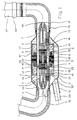
- Fig. 1 shows an exemplary embodiment of an inventive Blood pump with pump housing 3 and Stabilizer housing 2.
- a tubular Hollow body 1 in which in the axial direction, the fluid is promoted, is around the hollow body 1 around a motor stator 31 arranged with motor windings 33.
- a motor stator 31 drives a conveyor part 5, which has a Motor rotor 32 and a rotor hub 52 includes and stored in the interior of the tubular hollow body 1 is.
- the rotor hub 52 has a rotor blading 53 on.
- In the flow direction in front of and behind the rotor hub 52 are fluid directors 7 and 7 'with Fluid Leitgeschaufelept 72 and 72 'on the inner wall the tubular hollow body 1 fixed.
- a so-called hub gap 9 is formed.
- the motor rotor 32 over the motor stator 31 is the motor rotor 32, which with the rotor hub 52 is combined, set in rotation.
- Rotor gap 8 between rotor hub 52 and inner wall of the Hollow body 1 in this case has a width which the Flow losses keeps small and at the same time
- the engine losses are limited with increasing distance of the motor rotor 32 from the motor stator 31. For example, a particularly favorable Width of the rotor gap 8 between 0.5 and 2.5 mm exposed.
- the blood leaves the blood pump via a manifold 6 '. and flows into an aortic cannula 62, which at the manifold 6 ' attached by means of a releasable connecting element 63 is.
- a specially shielded cable 11a, which the Supply and signal cables for the motor stator 31, the axial stabilizer 12 and the sensors 60, 61 and 43 is over the cable gland 11 connected to the blood pump.
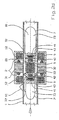
- Fig. 2 and Fig. 2a also show in each case in longitudinal section and in cross-section another exemplary Execution of a blood pump with a magnetically stored Rotor hub 52.
- the motor rotor 32 arranged respectively at the ends permanent magnetic bearing elements 42 combined, which are held in a version 4.
- the fluid guiding devices 7 and 7 ' are directly permanent magnetic Bearing elements 42 facing permanent magnetic Bearing elements 41 arranged.
- the permanent magnetic Bearing elements 41 and 42 are opposite poled.
- the axially directed, between the permanent magnetic bearing elements 41 and 42 training attraction ensures that the Conveying part 5 coaxial in the tubular hollow body. 1 is maintained and corrected radial deflections become.
- Position sensors 43 which also in the Fluid guide devices 7 and 7 'are arranged determine the width of the hub gap 9 and regulate this via the axial stabilizer 12.
- the axial stabilizer 12 is arranged in a stabilizer housing 2.
- the axial stabilizers 12, designed as coils, generate a magnetic field when the power is on, via the stabilizer housing 2 and the flux guides 10 is directed so that the conveying part 5 a stable axial position between the fluid guiding devices 7 and 7 'occupies.
- pressure sensors 60 and a flow sensor .61 for characterization attached to the flow.
- the from the motor rotor 32nd and the permanent magnetic bearing elements 42 as well the rotor blading 53 existing conveyor part. 5 is rotated via the motor stator 31 in rotation. Radial deviations in the rotation are through the opposite poled permanent magnetic Bearing elements intercepted while the axial stabilization via the position sensors 43 and the axial stabilizers 12 takes place.
- the concentration of Main mass of the permanent magnetic bearing elements 42nd allows in the region of the axis of the conveying part 5, the pump in a pulsatile mode of operation operate, for example by rapid speed change of the rotor.
- the permanent magnetic bearing elements 41 and 42 instead of a solid cylinder as permanent magnetic Rings also with axial magnetization educated. Any, known in the art Configurations can for the exact training of the permanent magnetic bearing elements 41 and 42 used become.
- an axial stabilizer 12 is provided, which cooperates with position sensors 43 and the via the fluid directors 7 and 7 'on the conveyor part 5 each end face acts and an electronic not shown here Control circuit used.
- the axial stabilizer 12 causes an active control of the axial position of Conveying part 5, wherein the stabilizing coils accordingly the control applied to currents and thereby an axial magnetic flux generate the axial magnetic flux of the permanent magnetic Elements superimposed and the regulation of axial position is used.
- Fig. 2b and Fig. 2c show in longitudinal and in cross section another exemplary embodiment of a Device according to the invention.
- the brackets 75 seen in the flow direction before and behind the Conveying part 5 are arranged, consist of a hub 73, with supports 74 on the inner wall of the tubular Hollow body 1 are attached.
- the supports 74 Here are exemplary at a distance of 90 ° around the hub 73 arranged. Basically, too, would be a prop 74 suffice.
- the holder 75 essentially serves the inclusion of the permanent magnetic bearing elements 41.
- Axial stabilizer provides axial stabilization 12, the position sensor 43 and a not shown control electronics.
- Fig. 2d are in a further exemplary embodiment the conveying part 5 and the fluid guide 7 conical educated.
- a conical rotor 80 of the conveyor part 5 increases in the flow direction and continues conically enlarging into a conical Guide 81 on.
- the permanent magnetic Bearing elements 41 and 42 are oppositely poled, the axial stabilization is done here via the Position sensors 43 in conjunction with the axial stabilizer 12th
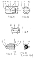
- Figures 3a and 3b show respectively in the longitudinal and in the Cross-section in detail an exemplary embodiment the bracket 75 with supports 74th
- FIG. 4 shows a conveying part 5 with the rotor hub 52, around which two rotor blades 53 and 53 'are arranged are.
- the arrangement of two or more rotor bluffings 53 allows the effect of Blade of the conveying part 5 to increase.
- Fig. 5 and Fig. 5a are in the longitudinal and in the cross section Fluid guiding devices 7 and 7 ', in which the permanent magnetic bearing element 41 is surrounded by the position sensor 43.
- the rib 724 is formed bent.
- ribs can on the front side 722 also convex and / or concave curvatures, radial blading, Micro-blades, ribs, grooves and eccentric Elevations 725 (FIG. 6c) of any shape or simply provided a roughness of the surface his.
- the only thing that matters is that it is this is to means by which the fluid at Rotation of the conveying part 5 radially from the hub gap 9 (see Fig. 8) is conveyed out.
- These agents can also be on the front of the Rotor hub 52 may be arranged.
- FIG. 7 advantageously effected additionally an improvement of the emergency running properties in case of failure of the axial stabilization.
- the hub 73 has an axial bore 726 on, which is flowed through by the fluid to be pumped and causes the fluid located in the hub gap 9 additional is transported radially.
- inventive Magnetic bearing not on cylindrical shapes of the magnets is limited. Further geometrical configurations the permanent magnetic bearing elements 41 and 42 are possible.
Landscapes
- Engineering & Computer Science (AREA)
- Health & Medical Sciences (AREA)
- Heart & Thoracic Surgery (AREA)
- Mechanical Engineering (AREA)
- Cardiology (AREA)
- Animal Behavior & Ethology (AREA)
- Public Health (AREA)
- Biomedical Technology (AREA)
- Hematology (AREA)
- Life Sciences & Earth Sciences (AREA)
- General Engineering & Computer Science (AREA)
- General Health & Medical Sciences (AREA)
- Anesthesiology (AREA)
- Veterinary Medicine (AREA)
- Power Engineering (AREA)
- Physics & Mathematics (AREA)
- Fluid Mechanics (AREA)
- Microelectronics & Electronic Packaging (AREA)
- Structures Of Non-Positive Displacement Pumps (AREA)
- External Artificial Organs (AREA)
- Measuring Fluid Pressure (AREA)
Abstract
Description
Beide vorgenannten Weiterbildungen beeinflussen die radiale Druckverteilung und generieren Ausgleichsströmungen zur Verhinderung von Totwassergebieten im Nabenspalt zwischen den Stirnseiten von Fluid-Leiteinrichtung und Förderteil.
- Fig. 1
- eine axiale Blutpumpe in Schnittdarstellung,
- Fig. 2
- eine axiale Fördervorrichtung mit Magnetlagerung; Axialstabilisierung und Positionssensorik in Längsschnittdarstellung,
- Fig. 2a
- eine Schnitt-A-A-Darstellung der axialen Fördervorrichtung gemäß Fig. 2,
- Fig. 2b
- eine axiale Fördervorrichtung mit Magnethalterung in Längsschnitt,
- Fig. 2c
- eine Schnitt-A-A-Darstellung der axialen Fördervorrichtung gemäß Fig. 2b,
- Fig. 2d
- eine axiale Fördervorrichtung mit konischem Förderteil in Längsschnittdarstellung,
- Fig. 3a
- eine Magnethalterung für eine axiale Fördervorrichtung,
- Fig. 3b
- die Magnethalterung gemäß Fig. 3a im Querschnitt,
- Fig. 4
- ein Förderteil mit Doppelbeschaufelung,
- Fig. 5
- eine Fluid-Leiteinrichtung mit Positionssensor und permanentmagnetischem Lagerelement,
- Fig. 5a
- die Fluid-Leiteinrichtung gemäß Fig. 5 in der Darstellung Schnitt-B-B,
- Fig. 6a
- eine schematische Vorderansicht der Stirnseite einer Rotornabe oder Nabe,
- Fig. 6b
- eine schematische Vorderansicht der Stirnseite einer weiteren Rotornabe oder Nabe,
- Fig. 6c
- eine schematische Vorderansicht der Stirnseite einer Rotornabe oder Nabe mit exzentrischer Erhöhung,
- Fig. 7
- eine schematische Schnittdarstellung eines Nabenspaltes, gebildet zwischen Förderteil und Nabe eines Befestigungselementes,
- Fig. 7a
- eine schematische Schnittdarstellung eines Nabenspaltes gebildet zwischen Förderteil und Nabe eines Befestigungselementes, und
- Fig. 8
- eine schematische Schnittdarstellung durch eine Nabe mit axialer Bohrung.
- 1
- Rohrförmiger Hohlkörper
- 2
- Stabilisatorgehäuse
- 3
- Pumpengehäuse
- 4
- Fassung
- 5
- Förderteil
- 6
- Krümmer
- 6'
- Krümmer
- 7
- Fluid-Leiteinrichtung
- 7'
- Fluid-Leiteinrichtung
- 8
- Rotorspalt
- 9
- Nabenspalt
- 10
- Flussleitstück
- 11
- Kabelstutzen
- 11a
- Kabel
- 12
- Axialstabilisator
- 31
- Motorstator
- 32
- Motorrotor
- 41
- permanentmagnetisches Lagerelement
- 42
- permanentmagnetisches Lagerelement
- 43
- Positionssensor
- 44 45 51 52
- Rotornabe
- 53
- Rotorbeschaufelung
- 60
- Drucksensor
- 61
- Flusssensor
- 62
- Aortenkanüle
- 63
- Verbindungselement
- 72
- Fluid-Leitbeschaufelung
- 72'
- Fluid-Leitbeschaufelung
- 73
- Nabe
- 74
- Stütze
- 75
- Halterung
- 76
- Nabenkappe
- 722
- Stirnseite
- 723
- Rippe
- 724
- Rippe
- 725
- Erhöhung
- 726
- Bohrung
- 80
- konischer Rotor
- 81
- konische Leiteinrichtung
Claims (10)
- Vorrichtung zur schonenden Förderung von einoder mehrphasigen Fluiden, bestehend aus einem rohrförmigen, das Fluid im Wesentlichen axial führenden Hohlkörper (1), in dem in axialer Ausrichtung ein mit einem außerhalb des Hohlkörpers (1) befindlichen Motorstator (31) in Rotation versetzbares Förderteil (5) gelagert ist, und vor und hinter dem Förderteil (5) je ein Befestigungselement (7, 7', 75) angeordnet ist,
dadurch gekennzeichnet, dass
in mindestens einem der Befestigungselemente (7, 7', 75) eine axial verlaufende Bohrung (726) angeordnet ist, die vom zu fördernden Fluid durchströmt wird und bewirkt, dass im Nabenspalt (9) befindliches Fluid zur Verhinderung von Totwassergebieten zusätzlich radial transportiert wird. - Vorrichtung nach Anspruch 1, dadurch gekennzeichnet, dass zur Strömungscharakterisierung Druck- und Flusssensoren (60, 61) in den Befestigungselementen (7, 7', 75) und/oder an oder in der Wandung des Hohlkörpers (1) angeordnet sind.
- Vorrichtung nach Anspruch 1 oder 2, dadurch gekennzeichnet, dass die Lagerelemente (41, 42) Flussleitstücke (10) aufweisen, die in den Befestigungselementen (7, 7', 75) angeordnet sind.
- Vorrichtung nach einem der Ansprüche 1 bis 3, dadurch gekennzeichnet, dass die Befestigungselemente (7, 7', 75) als Fluid-Leiteinrichtungen (7, 7') mit Fluidbeschaufelungen (72) ausgebildet sind.
- Vorrichtung nach einem der Ansprüche 1 bis 4, dadurch gekennzeichnet, dass an den dem Förderteil (5) zugewandten Stirnseiten (722, 723) der Befestigungselemente (7, 7', 75) und/oder an den Stirnseiten des Förderteiles (5) Rippen (723, 724) sowie Beschaufelungen, Rillen, konvexe und/oder konkave Ausbuchtungen oder exzentrisch angeordnete Erhöhungen (725) angebracht, sind.
- Vorrichtung nach einem der Ansprüche 1 bis 5, dadurch gekennzeichnet, dass das Förderteil (5) zwischen den Befestigungselementen (7, 7', 75), durch je einen Nabenspalt (9) getrennt, mittels sowohl in den Befestigungselementen (7, 7', 75) als auch im Förderteil (5) angeordneten, funktionell zusammenwirkenden, sich mit ihren magnetisch wirksamen Flächen gegenüberstehenden, in axialer Richtung magnetisierten, entgegengesetzt gepolten permanentmagnetischen Lagerelementen (41, 42) berührungsfrei gelagert ist und Sensoren (43) und Stabilisatoren (12) zur Positionserfassung und Positionskorrektur des Förderteiles (5) in den Befestigungselementen (7, 7', 75) und an oder in der Wandung des Hohlkörpers (1) angeordnet sind.
- Vorrichtung nach einem der Ansprüche 1 bis 6, dadurch gekennzeichnet, dass die Rotornabe (52) des Förderteiles (5) in axialem Abstand zwei Rotorbeschaufelungen (53) aufweist.
- Vorrichtung nach einem der Ansprüche 1 bis 7, dadurch gekennzeichnet, dass die Rotornabe (52) und die Naben (73) zylinderförmig ausgebildet und die Naben (73) durch Nabenkappen (76) an dem dem Förderteil (5) abgewandten Ende abgeschlossen sind.
- Vorrichtung nach einem der Ansprüche 1 bis 8, dadurch gekennzeichnet, dass das Förderteil (5) und die Halterungen (75), auch in der Ausbildung als Fluid-Leiteinrichtungen (7, 7') in Strömungsrichtung nichtzylindrisch vergrößert oder verjüngt ausgebildet sind.
- Vorrichtung zur schonenden Förderung von einoder mehrphasigen Fluiden, bestehend aus einer rohrförmigen, das Fluid führenden Hohlkörperanordnung (1), wobei der Rotor (32) des Elektromotors im Inneren der rohrförmigen Hohlkörperanordnung in axialer Ausrichtung als in Rotation versetzbares Förderteil (5) ausgebildet und gelagert ist, und mindestens einer Fluideinrichtung (7, 7'), die vor und/oder hinter dem Förderteil (5) angeordnet ist, dadurch gekennzeichnet, dass zur Verhinderung von Totwassergebieten mindestens ein Befestigungselement (7) eine axiale Bohrung (725) aufweist, die von zu förderndem Fluid durchströmt wird und bewirkt, dass im Nabenspalt (9) zwischen Fluid-Leiteinrichtung (7) und Förderteil (5) befindliches Fluid radial transportiert wird.
Priority Applications (1)
| Application Number | Priority Date | Filing Date | Title |
|---|---|---|---|
| EP07075547.5A EP1841044B1 (de) | 1999-04-20 | 2000-04-19 | Kreiselpumpe mit Auswaschung der Fugenspalte |
Applications Claiming Priority (3)
| Application Number | Priority Date | Filing Date | Title |
|---|---|---|---|
| DE19918841 | 1999-04-20 | ||
| DE19918841 | 1999-04-20 | ||
| EP00927001A EP1208630B1 (de) | 1999-04-20 | 2000-04-19 | Vorrichtung zur schonenden förderung von ein- oder mehrphasigen fluiden |
Related Parent Applications (1)
| Application Number | Title | Priority Date | Filing Date |
|---|---|---|---|
| EP00927001A Division EP1208630B1 (de) | 1999-04-20 | 2000-04-19 | Vorrichtung zur schonenden förderung von ein- oder mehrphasigen fluiden |
Related Child Applications (2)
| Application Number | Title | Priority Date | Filing Date |
|---|---|---|---|
| EP07075547.5A Division EP1841044B1 (de) | 1999-04-20 | 2000-04-19 | Kreiselpumpe mit Auswaschung der Fugenspalte |
| EP07075547.5A Division-Into EP1841044B1 (de) | 1999-04-20 | 2000-04-19 | Kreiselpumpe mit Auswaschung der Fugenspalte |
Publications (3)
| Publication Number | Publication Date |
|---|---|
| EP1416163A2 true EP1416163A2 (de) | 2004-05-06 |
| EP1416163A3 EP1416163A3 (de) | 2004-07-28 |
| EP1416163B1 EP1416163B1 (de) | 2014-04-09 |
Family
ID=32094806
Family Applications (3)
| Application Number | Title | Priority Date | Filing Date |
|---|---|---|---|
| EP03090442.9A Expired - Lifetime EP1415672B1 (de) | 1999-04-20 | 2000-04-19 | Pumpe mit Drucksensor |
| EP03090441.1A Expired - Lifetime EP1416163B1 (de) | 1999-04-20 | 2000-04-19 | Kreiselpumpe mit Auswaschung der Fugenspalte |
| EP07075547.5A Expired - Lifetime EP1841044B1 (de) | 1999-04-20 | 2000-04-19 | Kreiselpumpe mit Auswaschung der Fugenspalte |
Family Applications Before (1)
| Application Number | Title | Priority Date | Filing Date |
|---|---|---|---|
| EP03090442.9A Expired - Lifetime EP1415672B1 (de) | 1999-04-20 | 2000-04-19 | Pumpe mit Drucksensor |
Family Applications After (1)
| Application Number | Title | Priority Date | Filing Date |
|---|---|---|---|
| EP07075547.5A Expired - Lifetime EP1841044B1 (de) | 1999-04-20 | 2000-04-19 | Kreiselpumpe mit Auswaschung der Fugenspalte |
Country Status (2)
| Country | Link |
|---|---|
| EP (3) | EP1415672B1 (de) |
| DE (1) | DE50004809D1 (de) |
Families Citing this family (1)
| Publication number | Priority date | Publication date | Assignee | Title |
|---|---|---|---|---|
| EP3108809A1 (de) | 2015-06-22 | 2016-12-28 | Berlin Heart GmbH | Vorrichtung und verfahren zur druckmessung am herzen eines patienten |
Family Cites Families (6)
| Publication number | Priority date | Publication date | Assignee | Title |
|---|---|---|---|---|
| DE2919236C2 (de) * | 1979-05-12 | 1982-08-12 | Kernforschungsanlage Jülich GmbH, 5170 Jülich | Magnetisches Schwebelager für einen Rotor |
| US5078741A (en) * | 1986-10-12 | 1992-01-07 | Life Extenders Corporation | Magnetically suspended and rotated rotor |
| US5211546A (en) * | 1990-05-29 | 1993-05-18 | Nu-Tech Industries, Inc. | Axial flow blood pump with hydrodynamically suspended rotor |
| WO1996031934A1 (de) * | 1995-04-03 | 1996-10-10 | Sulzer Electronics Ag | Rotationsmaschine mit elektromagnetischem drehantrieb |
| JP3777490B2 (ja) * | 1997-01-31 | 2006-05-24 | 株式会社荏原製作所 | 送液装置及びその制御方法 |
| US5964694A (en) * | 1997-04-02 | 1999-10-12 | Guidant Corporation | Method and apparatus for cardiac blood flow assistance |
-
2000
- 2000-04-19 EP EP03090442.9A patent/EP1415672B1/de not_active Expired - Lifetime
- 2000-04-19 EP EP03090441.1A patent/EP1416163B1/de not_active Expired - Lifetime
- 2000-04-19 EP EP07075547.5A patent/EP1841044B1/de not_active Expired - Lifetime
- 2000-04-19 DE DE50004809T patent/DE50004809D1/de not_active Expired - Lifetime
Also Published As
| Publication number | Publication date |
|---|---|
| EP1841044B1 (de) | 2014-03-12 |
| EP1841044A3 (de) | 2011-05-11 |
| EP1416163A3 (de) | 2004-07-28 |
| EP1416163B1 (de) | 2014-04-09 |
| DE50004809D1 (de) | 2004-01-29 |
| EP1415672A3 (de) | 2005-03-16 |
| EP1415672A2 (de) | 2004-05-06 |
| EP1841044A2 (de) | 2007-10-03 |
| EP1415672B1 (de) | 2014-09-10 |
Similar Documents
| Publication | Publication Date | Title |
|---|---|---|
| EP1208630B1 (de) | Vorrichtung zur schonenden förderung von ein- oder mehrphasigen fluiden | |
| EP1360416B1 (de) | Vorrichtung zur axialen förderung von flüssigkeiten | |
| EP1727988B1 (de) | Pumpe | |
| DE69231633T2 (de) | Flüssigkeitspumpe mit magnetisch aufgehängtem laufrad | |
| EP0819330B1 (de) | Rotationsmaschine mit elektromagnetischem drehantrieb | |
| EP2051751B1 (de) | Blutpumpe | |
| DE3280454T2 (de) | Magnetisch gelagerter und angetriebener Kreiselpumpenapparat. | |
| DE10123139B4 (de) | Verfahren zur Regelung einer Unterstützungspumpe für Fluidfördersysteme mit pulsatilem Druck | |
| EP0699447B1 (de) | Zentrifugal-Blutpumpe | |
| EP0904117B1 (de) | Intravasale blutpumpe | |
| DE69629255T2 (de) | Herzunterstützungsvorrichtung | |
| EP2814534B1 (de) | Intravasale blutpumpe | |
| DE69401221T2 (de) | Künstliche Herzpumpe | |
| DE20007581U1 (de) | Vorrichtung zur axialen Förderung von fluiden Medien | |
| EP1261385B1 (de) | Blutpumpe | |
| DE20007580U1 (de) | Vorrichtung zur schonenden Förderung von ein- oder mehrphasigen Fluiden | |
| EP1013294A1 (de) | Diagonalflusspumpe | |
| EP1415672B1 (de) | Pumpe mit Drucksensor | |
| WO1998028543A2 (de) | Vorrichtung zur schonenden förderung von ein- und mehrphasigen fluiden |
Legal Events
| Date | Code | Title | Description |
|---|---|---|---|
| PUAI | Public reference made under article 153(3) epc to a published international application that has entered the european phase |
Free format text: ORIGINAL CODE: 0009012 |
|
| 17P | Request for examination filed |
Effective date: 20031216 |
|
| AC | Divisional application: reference to earlier application |
Ref document number: 1208630 Country of ref document: EP Kind code of ref document: P |
|
| AK | Designated contracting states |
Kind code of ref document: A2 Designated state(s): AT CH DE FR GB IT LI |
|
| PUAL | Search report despatched |
Free format text: ORIGINAL CODE: 0009013 |
|
| AK | Designated contracting states |
Kind code of ref document: A3 Designated state(s): AT CH DE FR GB IT LI |
|
| RIC1 | Information provided on ipc code assigned before grant |
Ipc: 7F 04D 29/04 B Ipc: 7F 16C 39/06 B Ipc: 7A 61M 1/10 B Ipc: 7H 02K 7/14 B Ipc: 7H 02K 7/09 A |
|
| AKX | Designation fees paid |
Designated state(s): AT CH DE FR GB IT LI |
|
| 17Q | First examination report despatched |
Effective date: 20051005 |
|
| RAP1 | Party data changed (applicant data changed or rights of an application transferred) |
Owner name: FORSCHUNGSZENTRUM JUELICH GMBH Owner name: BERLIN HEART GMBH |
|
| GRAP | Despatch of communication of intention to grant a patent |
Free format text: ORIGINAL CODE: EPIDOSNIGR1 |
|
| INTG | Intention to grant announced |
Effective date: 20131015 |
|
| GRAS | Grant fee paid |
Free format text: ORIGINAL CODE: EPIDOSNIGR3 |
|
| GRAA | (expected) grant |
Free format text: ORIGINAL CODE: 0009210 |
|
| AC | Divisional application: reference to earlier application |
Ref document number: 1208630 Country of ref document: EP Kind code of ref document: P |
|
| AK | Designated contracting states |
Kind code of ref document: B1 Designated state(s): AT CH DE FR GB IT LI |
|
| REG | Reference to a national code |
Ref country code: GB Ref legal event code: FG4D Free format text: NOT ENGLISH |
|
| REG | Reference to a national code |
Ref country code: CH Ref legal event code: EP Ref country code: AT Ref legal event code: REF Ref document number: 661800 Country of ref document: AT Kind code of ref document: T Effective date: 20140415 |
|
| REG | Reference to a national code |
Ref country code: DE Ref legal event code: R096 Ref document number: 50016368 Country of ref document: DE Effective date: 20140515 |
|
| REG | Reference to a national code |
Ref country code: CH Ref legal event code: PL |
|
| REG | Reference to a national code |
Ref country code: DE Ref legal event code: R097 Ref document number: 50016368 Country of ref document: DE |
|
| PG25 | Lapsed in a contracting state [announced via postgrant information from national office to epo] |
Ref country code: CH Free format text: LAPSE BECAUSE OF NON-PAYMENT OF DUE FEES Effective date: 20140430 Ref country code: LI Free format text: LAPSE BECAUSE OF NON-PAYMENT OF DUE FEES Effective date: 20140430 |
|
| PLBE | No opposition filed within time limit |
Free format text: ORIGINAL CODE: 0009261 |
|
| STAA | Information on the status of an ep patent application or granted ep patent |
Free format text: STATUS: NO OPPOSITION FILED WITHIN TIME LIMIT |
|
| 26N | No opposition filed |
Effective date: 20150112 |
|
| PG25 | Lapsed in a contracting state [announced via postgrant information from national office to epo] |
Ref country code: IT Free format text: LAPSE BECAUSE OF FAILURE TO SUBMIT A TRANSLATION OF THE DESCRIPTION OR TO PAY THE FEE WITHIN THE PRESCRIBED TIME-LIMIT Effective date: 20140409 |
|
| REG | Reference to a national code |
Ref country code: DE Ref legal event code: R097 Ref document number: 50016368 Country of ref document: DE Effective date: 20150112 |
|
| REG | Reference to a national code |
Ref country code: AT Ref legal event code: MM01 Ref document number: 661800 Country of ref document: AT Kind code of ref document: T Effective date: 20140419 |
|
| PG25 | Lapsed in a contracting state [announced via postgrant information from national office to epo] |
Ref country code: AT Free format text: LAPSE BECAUSE OF NON-PAYMENT OF DUE FEES Effective date: 20140419 |
|
| REG | Reference to a national code |
Ref country code: FR Ref legal event code: PLFP Year of fee payment: 17 |
|
| PGFP | Annual fee paid to national office [announced via postgrant information from national office to epo] |
Ref country code: GB Payment date: 20160421 Year of fee payment: 17 |
|
| PGFP | Annual fee paid to national office [announced via postgrant information from national office to epo] |
Ref country code: FR Payment date: 20160421 Year of fee payment: 17 |
|
| GBPC | Gb: european patent ceased through non-payment of renewal fee |
Effective date: 20170419 |
|
| REG | Reference to a national code |
Ref country code: FR Ref legal event code: ST Effective date: 20171229 |
|
| PG25 | Lapsed in a contracting state [announced via postgrant information from national office to epo] |
Ref country code: FR Free format text: LAPSE BECAUSE OF NON-PAYMENT OF DUE FEES Effective date: 20170502 |
|
| PG25 | Lapsed in a contracting state [announced via postgrant information from national office to epo] |
Ref country code: GB Free format text: LAPSE BECAUSE OF NON-PAYMENT OF DUE FEES Effective date: 20170419 |
|
| PGFP | Annual fee paid to national office [announced via postgrant information from national office to epo] |
Ref country code: DE Payment date: 20190430 Year of fee payment: 20 |
|
| REG | Reference to a national code |
Ref country code: DE Ref legal event code: R071 Ref document number: 50016368 Country of ref document: DE |