EP1415854B1 - Device for securing of loads - Google Patents
Device for securing of loads Download PDFInfo
- Publication number
- EP1415854B1 EP1415854B1 EP03024304A EP03024304A EP1415854B1 EP 1415854 B1 EP1415854 B1 EP 1415854B1 EP 03024304 A EP03024304 A EP 03024304A EP 03024304 A EP03024304 A EP 03024304A EP 1415854 B1 EP1415854 B1 EP 1415854B1
- Authority
- EP
- European Patent Office
- Prior art keywords
- load
- securing
- mounting posts
- vehicle
- loads according
- Prior art date
- Legal status (The legal status is an assumption and is not a legal conclusion. Google has not performed a legal analysis and makes no representation as to the accuracy of the status listed.)
- Expired - Lifetime
Links
Images

Classifications
-
- B—PERFORMING OPERATIONS; TRANSPORTING
- B60—VEHICLES IN GENERAL
- B60P—VEHICLES ADAPTED FOR LOAD TRANSPORTATION OR TO TRANSPORT, TO CARRY, OR TO COMPRISE SPECIAL LOADS OR OBJECTS
- B60P7/00—Securing or covering of load on vehicles
- B60P7/06—Securing of load
- B60P7/135—Securing or supporting by load bracing means
Definitions
- the invention relates to a device for securing cargo on transport vehicles according to the preamble of claim 1.
- Such devices for securing cargo in the longitudinal direction of a loading area of a transport vehicle are known from the prior art in various designs of partitions, loading bars and similar security elements.
- a bulkhead arrangement (bulkhead) of a freight transport vehicle has been disclosed, which is intended to form differently sized compartments for receiving freight items.
- the partition walls disclosed here extend from the floor area to the ceiling area. In the floor area perforated rails are used to lock the partition, while in the ceiling area a trolley system is provided for positioning or fixing the partition.
- the present invention seeks to provide a device which can be adjusted in a structurally simple and user-friendly manner as variable as possible in position and height of the charge and thereby independent and unaffected by other components or attachments prevents the transport vehicle slipping of the cargo in the longitudinal direction of the loading area.
- the device for securing cargo on transport vehicles of the aforementioned type is characterized by the features specified in claim 1. With regard to the further embodiment of the invention, reference is made to the claims 2 to 13.
- a device for securing cargo on a transport vehicle it is provided to secure the load at any point of the loading area, by one or more variable partitions against slipping in the longitudinal direction of the loading area.
- two support posts and at least one transverse profile or a plate are provided as a load securing element per partition.
- the support posts which can be mounted in relation to the vehicle longitudinal direction in almost any position on the longitudinal outer sides of a cargo area on the support means located there, in turn, have over their entire height about mounting options for the load securing elements.
- These mounting options on the support posts are provided on both sides in the vehicle longitudinal direction in the form of keyhole punches, so that the supports can be used left and right in front of and behind the load.
- the lower end of the support posts is designed as a fastener that a fast tool-free operable positive connection with the lashing strip is achieved.
- these fasteners consist of an angled support plate and two welded lashing hooks which are hooked in the assembled state of the support bracket to the cargo area hooked into the support means on the longitudinal outer sides of the cargo area.
- the lashing hooks alternately take on the moments that occur due to the load on the support posts in the longitudinal direction of the bed of the transport vehicle.
- the load securing elements which are preferably designed as hollow profiles in the form of a board, can by appropriate, to the keyhole punches compatible, fasteners connected at both ends, in the way with the support posts, that they can be used individually as height-adjustable loading bars can be used.
- the advantageous design of the possibility of attachment by keyhole punches also offers the possibility to secure this by a plugged bolt in the free bore-shaped area above the mounted load securing element, this against a lifting.
- An advantageous aspect of the variable design of the device according to the invention is particularly noticeable in the case of cargoes which, like cement sacks for example, easily slip under the influence of driving.
- the support means are formed on the longitudinal outer sides of the loading surface on which the support posts can be locked as Zurrlochmannn distributed over its length introduced lashing holes, so that the lashing strip equally as brackets for the support brackets according to the invention and for a cross lashing the cargo can be used with straps.
- the device according to the invention for securing cargo on transport vehicles that the device can be used autonomously, independently and uninfluenced by any further attachment or attachment parts of the transport vehicle.
- the disassembly of the device on storage compartment size causes no obstruction on the loading area and no loss of capacity.
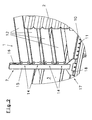
- FIG. 1 One of numerous possible embodiments of a device 1 according to the invention for securing cargo 2 on a loading area 3 of a transport vehicle 4 in the longitudinal direction of the vehicle is shown in FIG. 1 and consists essentially of perpendicular to the loading area 3 on the longitudinal outer sides 5, 6 of the loading area 3 Supporting posts 7, of which two are arranged opposite one another and are connected by load securing elements 8 in front of and behind the load 2, which secure them against slipping in the vehicle longitudinal direction.
- Fig. 1 it can be seen how the arranged on the longitudinal outer sides 5,6 of the loading surface 3 support means 9, by their design as Zurrlochmannn 10 with distributed over their length lashing holes 11, allow a locking of the support posts 7 directly to the charge 2. Furthermore, it is made clear in Fig.
- the device 1 for securing the charge 2 against slipping in the vehicle longitudinal direction.
- the cargo securing elements 8 in the form of rectangular hollow profiles 12 shown in the embodiment shown provide optimum securing for the cargo 2 illustrated by way of example in the form of palletized cement bags.
- a pallet of the charge 2 has been removed in FIG.
- advantageous embodiment of the device according to the invention for securing cargo on transport vehicles is clearly seen that the device 1 is self-sufficient in itself. Neither further charge structures are required, nor are any existing structures 13, as shown in FIG. 1, hindered by the device 1.
- Fig. 2 shows a side of an embodiment of the assembled device 1 according to the invention and their connection to the loading area 3 via the lashing strips 10 on the longitudinal outer sides 5.6 of the loading area 3.
- Four rectangular hollow sections 12 are on corresponding Fastening elements 14 at both ends, as load securing elements 8 connected to the support posts 7.
- the profile tubes 15 of the support posts 7 are provided on both narrow sides with keyhole punches 16 over the entire length.
- this double-sided keyholes 16 is a variable use of the support posts 7 left and right, both before and behind the charge possible.
- the fastening means 17 at the lower end of the support posts 7, consisting of an angled support plate 18 and two pull hooks 19 (shown in Figure 3) in Fig. 2, the supporting function of the support plate 18 can be seen on the profile of Zurrlochor 10. Further, in Fig. 2, the distribution of Zurrlöcher 11 over the entire length of Zurrlochance 10 is shown in fragmentary form. This close uniform distribution allows positioning of the support posts 7 at almost any longitudinal position of the loading area. 3
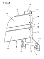
- FIG. 3 again shows two load securing elements 8 connected to the support bracket 7 in a broken view. Due to the visible here free bore-like areas of the keyhole punches 16 above the mounted load securing elements 8 is a backup of the load securing elements 8 by a plugged through this hole bolts (not shown) possible.
Abstract
Description
Die Erfindung bezieht sich auf eine Vorrichtung zur Sicherung von Ladung auf Transportfahrzeugen gemäß dem Oberbegriff des Anspruchs 1.The invention relates to a device for securing cargo on transport vehicles according to the preamble of
Derartige Vorrichtungen zur Ladegutsicherung in Längsrichtung einer Ladefläche eines Transportfahrzeuges sind aus dem Stand der Technik in verschiedensten Ausführungen von Trennwänden, Ladebalken und ähnlichen Sicherungselementen bekannt.Such devices for securing cargo in the longitudinal direction of a loading area of a transport vehicle are known from the prior art in various designs of partitions, loading bars and similar security elements.
So beschreiben beispielsweise die
Aus der
Aus der
Ausgehend von diesem Stand der Technik liegt der Erfindung die Aufgabe zugrunde, eine Vorrichtung zu schaffen, welche in einer konstruktiv einfachen und bedienerfreundlichen Art und Weise möglichst variabel in Position und Höhe der Ladung angepasst werden kann und dabei unabhängig und unbeeinflusst von weiteren Auf- oder Anbauteilen des Transportfahrzeuges ein Verrutschen der Ladung in Längsrichtung der Ladefläche verhindert.Based on this prior art, the present invention seeks to provide a device which can be adjusted in a structurally simple and user-friendly manner as variable as possible in position and height of the charge and thereby independent and unaffected by other components or attachments prevents the transport vehicle slipping of the cargo in the longitudinal direction of the loading area.
Zur Lösung der gestellten Aufgabe zeichnet sich die Vorrichtung zur Sicherung von Ladung auf Transportfahrzeugen der vorstehend genannten Art durch die im Anspruch 1 angegebenen Merkmale aus. Hinsichtlich der weiteren Ausgestaltung der Erfindung wird auf die Ansprüche 2 bis 13 verwiesen.To achieve the object, the device for securing cargo on transport vehicles of the aforementioned type is characterized by the features specified in
Bei einer Vorrichtung zur Sicherung von Ladung auf einem Transportfahrzeug gemäß der Erfindung ist vorgesehen, das Ladegut an jeder beliebigen Stelle der Ladefläche, durch eine oder mehrere variable Trennwände gegen Verrutschen in Längsrichtung der Ladefläche zu sichern. Dazu sind pro Trennwand zwei Halterungsstützen und mindestens ein Querprofil oder eine Platte als Ladungssicherungselement vorgesehen. Die Halterungsstützen, die sich in Bezug zur Fahrzeuglängsrichtung in nahezu jeder Position an den Längsaußenseiten einer Ladefläche an den dort befindlichen Halterungsmitteln anbringen lassen, verfügen wiederum über ihre gesamte Höhe über Befestigungsmöglichkeiten für die Ladungssicherungselemente. Diese Befestigungsmöglichkeiten an den Halterungsstützen sind beidseitig in Fahrzeuglängsrichtung in Form von Schlüssellochstanzungen vorgesehen, wodurch die Stützen links und rechts vor und hinter der Ladung eingesetzt werden können. Das untere Ende der Halterungsstützen ist derart als Befestigungsmittel gestaltet, dass eine schnelle werkzeuglos bedienbare formschlüssige Verbindung mit den Zurrlochleisten erreicht wird. Dazu bestehen diese Befestigungsmittel aus einem abgewinkelten Stützblech und zwei angeschweißten Zurrhaken, welche im montierten Zustand der Halterungsstütze zur Ladefläche gerichtet in die Halterungsmittel an den Längsaußenseiten der Ladefläche eingehakt sind. In Verbindung mit dem Stützblech, welches sich im montierten Zustand der Halterungsstütze nach unten auf das Profil der Halterungsmittel an den Längsaußenseiten abstützt, nehmen die Zurrhaken wechselseitig die Momente auf, die durch die Belastung der Halterungsstützen in Längsrichtung der Ladefläche des Transportfahrzeugs auftreten.
Die Ladungssicherungselemente, welche vorzugsweise als Hohlprofile in Brettform ausgeführt sind, können durch entsprechende, zu den Schlüssellochstanzungen kompatible, Befestigungselemente an beiden Enden, in der Art mit den Halterungsstützen verbunden werden, dass sie einzeln verwendet wie höhenverstellbare Ladebalken eingesetzt werden können. Mehrere Hohlprofile übereinander an den Halterungsstützen angebracht, bilden eine Ladungssicherung in der Art einer Trennwand. Die vorteilhafte Gestaltung der Befestigungsmöglichkeit durch Schlüssellochstanzungen bietet zusätzlich die Möglichkeit, durch einen gesteckten Bolzen im freien bohrungsförmigen Bereich oberhalb des montierten Ladungssicherungselementes, dieses gegen ein Ausheben zu sichern.
Ein vorteilhafter Aspekt der variablen Gestaltung der erfindungsgemäßen Vorrichtung kommt insbesondere bei Ladungen zum Tragen, die wie beispielsweise Zementsäcke, unter Fahreinflüssen leicht verrutschen. Durch die Positioniermöglichkeit der Vorrichtung in nahezu jeder Fahrzeuglängsposition ist es möglich, direkt vor und hinter der zu sichernden Ladung eine Vorrichtung zur Ladungssicherung in einer der Ladung in Höhe und Art angepassten Ausführung anzubringen. Durch den Einsatz mehrerer in Ausführung beliebiger Vorrichtungen gemäß Erfindung ist es denkbar, eine Ladefläche in Bereiche für den sicheren Transport unterschiedlicher Güter zu unterteilen.
Gemäß einer weiteren vorteilhaften Ausbildung der Erfindung sind die Halterungsmittel an den Längsaußenseiten der Ladefläche, an denen die Halterungsstützen arretiert werden können, als Zurrlochleisten mit über ihre Länge verteilt eingebrachten Zurrlöchern ausgebildet, so dass die Zurrlochleisten gleichermaßen als Halterungen für die erfindungsgemäßen Halterungsstützen und für eine Querverzurrung der Ladung mit Spanngurten verwendet werden können. Des weiteren ist durch die Zurrlochleisten die Möglichkeit gegeben, die Halterungsstützen für extreme Belastungen in Fahrzeuglängsrichtung schräg nach vorne oder hinten abzuspannen. Besonders vorteilhaft für die erfindungsgemäße Vorrichtung zur Ladungssicherung auf Transportfahrzeugen ist es, dass die Vorrichtung in sich autark, unabhängig und unbeeinflusst von eventuellen weiteren Auf- oder Anbauteilen des Transportfahrzeuges eingesetzt werden kann. Bei Nichtbenutzung wird durch die Demontagemöglichkeit der Vorrichtung auf Staufachgröße keine Behinderung auf der Ladefläche und kein Ladekapazitätsverlust verursacht.In a device for securing cargo on a transport vehicle according to the invention, it is provided to secure the load at any point of the loading area, by one or more variable partitions against slipping in the longitudinal direction of the loading area. For this purpose, two support posts and at least one transverse profile or a plate are provided as a load securing element per partition. The support posts, which can be mounted in relation to the vehicle longitudinal direction in almost any position on the longitudinal outer sides of a cargo area on the support means located there, in turn, have over their entire height about mounting options for the load securing elements. These mounting options on the support posts are provided on both sides in the vehicle longitudinal direction in the form of keyhole punches, so that the supports can be used left and right in front of and behind the load. The lower end of the support posts is designed as a fastener that a fast tool-free operable positive connection with the lashing strip is achieved. For this purpose, these fasteners consist of an angled support plate and two welded lashing hooks which are hooked in the assembled state of the support bracket to the cargo area hooked into the support means on the longitudinal outer sides of the cargo area. In conjunction with the support plate, which is supported in the assembled state of the support bracket down on the profile of the support means on the longitudinal outer sides, the lashing hooks alternately take on the moments that occur due to the load on the support posts in the longitudinal direction of the bed of the transport vehicle.
The load securing elements, which are preferably designed as hollow profiles in the form of a board, can by appropriate, to the keyhole punches compatible, fasteners connected at both ends, in the way with the support posts, that they can be used individually as height-adjustable loading bars can be used. Several hollow profiles mounted one above the other on the support posts, form a load securing in the manner of a partition. The advantageous design of the possibility of attachment by keyhole punches also offers the possibility to secure this by a plugged bolt in the free bore-shaped area above the mounted load securing element, this against a lifting.
An advantageous aspect of the variable design of the device according to the invention is particularly noticeable in the case of cargoes which, like cement sacks for example, easily slip under the influence of driving. Due to the possibility of positioning the device in virtually any vehicle longitudinal position, it is possible to attach directly and in front of the load to be secured a device for securing cargo in an adapted to the charge in height and type execution. By using several in the execution of any devices according to the invention, it is conceivable to divide a cargo area in areas for the safe transport of different goods.
According to a further advantageous embodiment of the invention, the support means are formed on the longitudinal outer sides of the loading surface on which the support posts can be locked as Zurrlochleisten distributed over its length introduced lashing holes, so that the lashing strip equally as brackets for the support brackets according to the invention and for a cross lashing the cargo can be used with straps. Furthermore, given by the lashing bars the possibility to clamp the support brackets for extreme loads in the vehicle longitudinal direction obliquely forward or backward. It is particularly advantageous for the device according to the invention for securing cargo on transport vehicles that the device can be used autonomously, independently and uninfluenced by any further attachment or attachment parts of the transport vehicle. When not in use, the disassembly of the device on storage compartment size causes no obstruction on the loading area and no loss of capacity.
Eine detaillierte Beschreibung des Gegenstandes der Erfindung erfolgt nun anhand eines Ausführungsbeispieles. In der Zeichnung stellt im einzelnem dar:
- Fig. 1
- eine perspektivische Ansicht eines Transportfahrzeuges, insbesondere eines Nutzfahrzeug Sattelaufliegers mit einer Transportsicherung gemäß der Erfindung;
- Fig. 2
- eine vergrößerte Darstellung einer perspektivischen Teilansicht der erfindungsgemäßen Vorrichtung als Ausschnitt X der Fig. 1;
- Fig. 3
- eine perspektivische, teilweise abgebrochen dargestellte Ansicht eines unteren Teiles einer Halterungsstütze mit Befestigungsmitteln am unteren Ende mit zwei montierten, abgebrochen dargestellten Ladungssicherungselementen in Profilform;
- Fig. 1
- a perspective view of a transport vehicle, in particular a commercial vehicle semitrailer with a transport lock according to the invention;
- Fig. 2
- an enlarged view of a partial perspective view of the device according to the invention as a section X of Fig. 1;
- Fig. 3
- a perspective, partially broken away view of a lower part of a support bracket with fixing means at the bottom with two mounted, shown broken off cargo securing elements in profile form;
Eine von zahlreichen möglichen Ausführungsformen einer erfindungsgemäßen Vorrichtung 1 zur Sicherung von Ladung 2 auf einer Ladefläche 3 eines Transportfahrzeuges 4 in Längsrichtung des Fahrzeuges ist in Fig. 1 dargestellt und besteht im wesentlichen aus senkrecht zur Ladefläche 3 an den Längsaußenseiten 5,6 der Ladefläche 3 angeordneten Halterungsstützen 7, von denen jeweils zwei gegenüberliegend angeordnet sind und durch Ladungssicherungselemente 8 vor und hinter der Ladung 2 verbunden sind, welche diese gegen Verrutschen in Fahrzeuglängsrichtung sichern. In Fig. 1 ist zu sehen, wie die an den Längsaußenseiten 5,6 der Ladefläche 3 angeordneten Halterungsmittel 9, durch ihre Ausführung als Zurrlochleisten 10 mit über ihre Länge verteilten Zurrlöchern 11, eine Arretierung der Halterungsstützen 7 unmittelbar an der Ladung 2 ermöglichen. Weiterhin ist in Fig. 1 deutlich gemacht, wie durch die variable Höhenanordnung und durch die variable Stückzahl der Ladungssicherungselemente 8, die Vorrichtung 1 zur Sicherung der Ladung 2 gegen Verrutschen in Fahrzeuglängsrichtung optimal der jeweiligen Ladung angepasst werden kann. Die in der gezeigten Ausführungsform dargestellten Ladungssicherungselemente 8 in Form von rechteckförmigen Hohlprofilen 12 bieten für die beispielhaft dargestellte Ladung 2 in Form von palettierten Zementsäcken, eine optimale Sicherung. Zur besseren Sichtbarkeit der Vorrichtung 1 ist in Fig. 1 eine Palette der Ladung 2 entnommen worden.
Bei der in Fig. 1 dargestellten vorteilhaften Ausführungsform der erfindungsgemäßen Vorrichtung zur Sicherung von Ladung auf Transportfahrzeugen ist deutlich erkennbar, dass die Vorrichtung 1 in sich autark ist. Es werden weder weitere Ladungsaufbauten benötigt, noch werden eventuell vorhandene Aufbauten 13, wie in Fig. 1 dargestellt, durch die Vorrichtung 1 behindert. Für eine zusätzliche Sicherung der Ladung 2 in Fahrzeugquerrichtung, sind die Zurrlochleisten 10 an den Längsaußenseiten 5,6 der Ladefläche 3 zur Anbringung von Spanngurten, Rungen oder anderen Ladungssicherungsmitteln (nicht dargestellt) frei zugänglich. Fig. 2, als vergrößerter Ausschnitt aus Fig. 1, zeigt eine Seite einer Ausführungsform der montierten erfindungsgemäßen Vorrichtung 1 und deren Verbindung mit der Ladefläche 3 über die Zurrlochleisten 10 an den Längsaußenseiten 5,6 der Ladefläche 3. Vier rechteckförmige Hohlprofile 12 sind über entsprechende Befestigungselemente 14 an beiden Enden, als Ladungssicherungselemente 8 mit den Halterungsstützen 7 verbunden. Für die formschlüssige werkzeuglos bedienbare Schnellverbindung sind die Profilrohre 15 der Halterungsstützen 7 an beiden Schmalseiten mit Schlüssellochstanzungen 16 über die gesamte Länge versehen.
Durch diese beidseitig vorhandenen Schlüssellochstanzungen 16 ist eine variable Verwendung der Halterungsstützen 7 links und rechts, sowohl vor als auch hinter der Ladung möglich.
Von den Befestigungsmitteln 17 am unteren Ende der Halterungsstützen 7, bestehend aus einem abgewinkeltem Stützblech 18 und zwei Zughaken 19 (in Fig.3 dargestellt), ist in Fig. 2 die abstützende Funktion des Stützbleches 18 auf das Profil der Zurrlochleiste 10 zu erkennen. Ferner ist in Fig. 2 die Verteilung der Zurrlöcher 11 über die gesamte Länge der Zurrlochleiste 10 ausschnittweise wiedergegeben. Diese enge gleichmäßige Verteilung ermöglicht eine Positionierung der Halterungsstützen 7 an nahezu jeder Längsposition der Ladefläche 3.One of numerous possible embodiments of a
In the illustrated in Fig. 1 advantageous embodiment of the device according to the invention for securing cargo on transport vehicles is clearly seen that the
By this double-
Of the fastening means 17 at the lower end of the
Die in Fig. 3 nach oben abgebrochen gezeichnete vorteilhafte Ausführungsform einer Halterungsstütze 7 gemäß der Erfindung, ist von der im montierten Zustand der Ladefläche 3 zugewandten Seite dargestellt. In dieser Ansicht werden die an das Stützblech 18 angeschweißten Zughaken 19 der Befestigungsmittel 17 am unteren Ende der Halterungsstütze 7 deutlich. Gleichzeitig zeigt Fig. 3 nochmals zwei mit der Halterungsstütze 7 verbundene Ladungssicherungselemente 8 in abgebrochener Darstellung. Durch die hier sichtbaren freien bohrungsähnlichen Bereiche der Schlüssellochstanzungen 16 oberhalb der montierten Ladungssicherungselemente 8 ist eine Sicherung der Ladungssicherungselemente 8 durch einen durch diese Bohrung gesteckten Bolzen (nicht dargestellt) möglich.The abridged in Fig. 3 drawn above advantageous embodiment of a
Claims (13)
- Device for securing loads on transporting vehicles, which device can be locked to the outer longitudinal sides (5, 6) of a load-carrying area (3), after the fashlon of a partition, approximately transversely to the direction of travel (F) and in different longitudinal positions, on mounting means which are arranged in the longitudinal direction of the vehicle on the said outer longitudinal sides (5, 6) of the load-carrying area (3), in which device at least two mounting posts (7) aligned approximately perpendicularly to the load-carrying area (3) are arranged in opposite positions at the outer longitudinal sides (5, 6) of the load-carrying area (3), can be locked in place there In the mounting means, which are in the form of tracks (10) containing holes for lashings, and are connected together by at least one load-securing member (8), wherein the load-securing members (8), which are connected to the mounting posts (7) transversely to the longitudinal direction of the vehicle, can be arranged in variable numbers and at variable heights to suit the given load.
- Device for securing loads according to claim 1, characterised in that at least two mounting posts (7) aligned approximately perpendicularly to the load-carrying area (3) are arranged in opposite positions at the outer longitudinal sides (5, 6) of the load-carrying area (3), can be locked in place there in mounting means which are in the form of tracks (10) containing holes for lashings, and are detachably connected together by at least one load-securing member (8).
- Device for securing loads according to claim 1, characterised in that the tracks (10) containing holes for lashings, which are arranged at the outer longitudinal sides (5, 6) of the load-carrying area (3), are provided with holes (11) for lashings which are distributed along their length.
- Device for securing loads according to one of claims 1 to 3, characterised in that the mounting posts (7) comprise a tubular profile (15) of rectangular cross-section whose bottom end takes the form of a fastening means (17).
- Device for securing loads according to claim 4, characterised in that the fastening means (17) at the bottom ends of the mounting posts (7) allow a positively engaged quick connection able to be made without tools to be made to the tracks (10) containing holes for lashings which extend along the outer longitudinal sides of the load-carrying area (3) in the longitudinal direction of the vehicle.
- Device for securing loads according to claim 4, characterised in that the fastenings means (17) at the bottom ends of the mounting posts (7) allow a positively engaged quick connection able to be made without tools to be made to the tracks (10) containing holes for lashings which extend along the outer longitudinal sides of the load-carrying area (3) in the longitudinal direction of the vehicle, and are able to withstand loads on the mounting posts (7) directed in the direction of travel and in the opposite direction.
- Device for securing loads according to one of claims 4 to 6, characterised in that the fastening means (17) at the bottom ends of the mounting posts (7) comprise a support plate (18) projecting at an angle and at least two traction hooks (19).
- Device for securing loads according to one of claims 4 to 8, characterised in that the fastening means (17) at the bottom ends of the mounting posts (7) may comprise a support plate (18) projecting at an angle in conjunction with at least two engaging pins.
- Device for securing loads according to one of claims 1 to 8, characterised in that the mounting posts (7) which take the form of tubular profiles (15) have facilities for positively engaged connection to at least one load-securing member on at least one side, on the sides facing in the longitudinal direction of the vehicle.
- Device for securing loads according to one of claims 1 to 8, characterised in that the mounting posts (7) which take the form of tubular profiles (15) have facilities for positively engaged connection to at least one load-securing member on at least one side, on the sides facing in the longitudinal direction of the vehicle, and this connecting facility takes the forms of punched keyholes (16).
- Device for securing loads according to claim 10, characterised in that the load-securing members (8) which point in the transverse direction of the vehicle are in the form of hollow profiles (12) of rectangular cross-section whose height covers not more than two punched keyholes (16) in the mounting posts (7).
- Device for securing loads according to claim 10, characterised in that the load-securing members (8) which point in the transverse direction of the vehicle are in the form of one-piece solid plates whose height covers at least two punched keyholes (16) in the mounting posts (7).
- Device for securing loads according to one of claims 1 to 11, characterised in that the load-securing members (8) which point in the transverse direction of the vehicle have, at the ends, fastening members (14) which allow a positively engaged quick connection able to be made without tools to be made to the mounting posts (7).
Applications Claiming Priority (2)
| Application Number | Priority Date | Filing Date | Title |
|---|---|---|---|
| DE10250463A DE10250463A1 (en) | 2002-10-30 | 2002-10-30 | Load securing device |
| DE10250463 | 2002-10-30 |
Publications (5)
| Publication Number | Publication Date |
|---|---|
| EP1415854A2 EP1415854A2 (en) | 2004-05-06 |
| EP1415854A3 EP1415854A3 (en) | 2005-11-16 |
| EP1415854B1 true EP1415854B1 (en) | 2007-12-26 |
| EP1415854B8 EP1415854B8 (en) | 2008-03-05 |
| EP1415854B2 EP1415854B2 (en) | 2012-07-25 |
Family
ID=32087285
Family Applications (1)
| Application Number | Title | Priority Date | Filing Date |
|---|---|---|---|
| EP03024304A Expired - Lifetime EP1415854B2 (en) | 2002-10-30 | 2003-10-24 | Device for securing of loads |
Country Status (5)
| Country | Link |
|---|---|
| EP (1) | EP1415854B2 (en) |
| AT (1) | ATE382002T1 (en) |
| DE (2) | DE10250463A1 (en) |
| DK (1) | DK1415854T3 (en) |
| ES (1) | ES2298458T5 (en) |
Cited By (1)
| Publication number | Priority date | Publication date | Assignee | Title |
|---|---|---|---|---|
| EP2540568A1 (en) | 2011-06-29 | 2013-01-02 | Schmitz Cargobull AG | Commercial vehicle |
Families Citing this family (7)
| Publication number | Priority date | Publication date | Assignee | Title |
|---|---|---|---|---|
| DE202006006168U1 (en) * | 2006-04-13 | 2006-07-20 | Hoelzer, Oliver | Safety device for loaded freight on transport vehicles has bogies with side-panel segments attached to an upper roof rail in a suspended structure |
| DE202008014035U1 (en) | 2008-10-21 | 2010-03-04 | Humbaur Gmbh | charging fuse |
| EP2993112B2 (en) | 2014-09-05 | 2022-02-16 | Helmut Fliegl | Post system for a roof structure of a trailer or commercial vehicle |
| DE102015010486B4 (en) * | 2015-08-17 | 2020-03-19 | Uwe Dominik | Load securing and transport vehicle |
| DE102017120200B4 (en) | 2016-09-13 | 2023-01-05 | Schmitz Cargobull Aktiengesellschaft | Shoring for a tarpaulin structure of a commercial vehicle |
| DE102018122634B4 (en) * | 2018-09-17 | 2020-07-02 | allsafe GmbH & Co.KG | Load securing system and vehicle comprising such a system and a method for securing loads |
| DE202020101948U1 (en) | 2020-04-08 | 2020-04-17 | Weka Fahrzeugbau Gmbh | Load securing of a transport vehicle |
Family Cites Families (11)
| Publication number | Priority date | Publication date | Assignee | Title |
|---|---|---|---|---|
| US2155872A (en) † | 1937-03-31 | 1939-04-25 | Gen Motors Corp | Freight car loading apparatus |
| US3741127A (en) * | 1971-09-01 | 1973-06-26 | Evans Prod Co | Trolley system for freight bracing bulkhead assemblies |
| CA1239052A (en) * | 1986-06-23 | 1988-07-12 | Joseph W. Cox | Adjustable load retainer and retention means for use in a transport vehicle |
| US5386674A (en) * | 1992-09-17 | 1995-02-07 | Joseph T. Ryerson & Son, Inc. | Two piece bulkhead door for rail cars and the like |
| DE9405528U1 (en) * | 1994-03-31 | 1994-11-24 | Koegel Fahrzeugwerke Ag | Device for the height-adjustable arrangement of loading beams |
| DE19533784A1 (en) † | 1995-09-13 | 1997-03-20 | Peter Schmitz | Lorry with loading surfaces one above other |
| DE19538077A1 (en) † | 1995-10-13 | 1997-04-17 | Deutsche Bahn Ag | Removable stanchion for railway goods wagon |
| DE20101312U1 (en) † | 2000-09-15 | 2001-06-13 | Ancra Jungfalk Gmbh & Co Kg | Device for securing cargo on the loading surface of a vehicle |
| FR2821814B1 (en) * | 2001-03-06 | 2003-08-08 | Patrigeon S A Ets | ROAD TRANSPORT VEHICLE |
| DE20210354U1 (en) † | 2002-07-03 | 2002-09-12 | Ancra Jungfalk Gmbh & Co Kg | Device for securing cargo on a loading surface or the like. Facility |
| DE20306124U1 (en) * | 2003-04-14 | 2003-07-10 | Puhl Stefan | Modular load securing system for articulated lorry, comprising vertical elements, partition, tensioning rope, and horizontal bars |
-
2002
- 2002-10-30 DE DE10250463A patent/DE10250463A1/en not_active Withdrawn
-
2003
- 2003-10-24 DK DK03024304T patent/DK1415854T3/en active
- 2003-10-24 EP EP03024304A patent/EP1415854B2/en not_active Expired - Lifetime
- 2003-10-24 DE DE50308883T patent/DE50308883D1/en not_active Expired - Lifetime
- 2003-10-24 AT AT03024304T patent/ATE382002T1/en active
- 2003-10-24 ES ES03024304T patent/ES2298458T5/en not_active Expired - Lifetime
Cited By (2)
| Publication number | Priority date | Publication date | Assignee | Title |
|---|---|---|---|---|
| EP2540568A1 (en) | 2011-06-29 | 2013-01-02 | Schmitz Cargobull AG | Commercial vehicle |
| DE102011107350A1 (en) | 2011-06-29 | 2013-01-03 | Schmitz Cargobull Ag | commercial vehicle |
Also Published As
| Publication number | Publication date |
|---|---|
| EP1415854B2 (en) | 2012-07-25 |
| ES2298458T5 (en) | 2013-07-18 |
| DK1415854T3 (en) | 2008-05-05 |
| EP1415854A3 (en) | 2005-11-16 |
| DE10250463A1 (en) | 2004-05-19 |
| EP1415854B8 (en) | 2008-03-05 |
| ES2298458T3 (en) | 2008-05-16 |
| EP1415854A2 (en) | 2004-05-06 |
| DE50308883D1 (en) | 2008-02-07 |
| ATE382002T1 (en) | 2008-01-15 |
Similar Documents
| Publication | Publication Date | Title |
|---|---|---|
| DE1530765A1 (en) | Device for hanging cargo on the roof of vehicles | |
| EP1415854B1 (en) | Device for securing of loads | |
| EP2581264B1 (en) | Foldable shelf | |
| EP3235681A1 (en) | Commercial vehicle structure with load securing for coils in particular | |
| EP2687404B1 (en) | Assembly for securing loads | |
| DE102005005517B4 (en) | Modular load securing system | |
| EP2703216B1 (en) | Commercial vehicle superstructure with load securing for double decker operation | |
| DE102008019162B4 (en) | vehicle body | |
| EP3243678A1 (en) | Commercial vehicle structure | |
| DE102006058603B4 (en) | Structure for a truck, trailer or the like | |
| EP0743261B1 (en) | Support for the storage and/or the transport of glass sheet packages | |
| DE102013202839A1 (en) | Quick change frame for changing bodywork of transport vehicle to e.g. dump truck bodywork, has locking points arranged to form connection with vehicle frame, where frame converts bodyworks of transport vehicle for transportation purposes | |
| DE19706493A1 (en) | Goods vehicle with additional upper load platforms | |
| EP3247589A1 (en) | Transport vehicle | |
| DE102016115786B4 (en) | Load securing device for commercial vehicles | |
| EP3141424B1 (en) | Load securing and transport vehicle | |
| DE2519272C2 (en) | ||
| DE102017120200B4 (en) | Shoring for a tarpaulin structure of a commercial vehicle | |
| EP1043188A2 (en) | Arrangements in a loading space for transport vehicles or containers | |
| DE102010016552B4 (en) | Side member for load securing | |
| DE202006001168U1 (en) | Transporting container, especially lattice wall container, has blocking bar inside container to place against loaded goods for their security, and is fitted in perforated walls of container | |
| DE102015121678B4 (en) | Support structure for transporting objects | |
| EP2969646B1 (en) | Load carrier for use in a logistics system | |
| EP1028024A2 (en) | Device for attaching at least one fixation point on a profile for a fastening system and vehicle with profile | |
| DE3522825C2 (en) |
Legal Events
| Date | Code | Title | Description |
|---|---|---|---|
| PUAI | Public reference made under article 153(3) epc to a published international application that has entered the european phase |
Free format text: ORIGINAL CODE: 0009012 |
|
| AK | Designated contracting states |
Kind code of ref document: A2 Designated state(s): AT BE BG CH CY CZ DE DK EE ES FI FR GB GR HU IE IT LI LU MC NL PT RO SE SI SK TR |
|
| AX | Request for extension of the european patent |
Extension state: AL LT LV MK |
|
| PUAL | Search report despatched |
Free format text: ORIGINAL CODE: 0009013 |
|
| AK | Designated contracting states |
Kind code of ref document: A3 Designated state(s): AT BE BG CH CY CZ DE DK EE ES FI FR GB GR HU IE IT LI LU MC NL PT RO SE SI SK TR |
|
| AX | Request for extension of the european patent |
Extension state: AL LT LV MK |
|
| RIC1 | Information provided on ipc code assigned before grant |
Ipc: 7B 60P 7/14 A |
|
| AKX | Designation fees paid |
Designated state(s): AT BE BG CH CY CZ LI |
|
| AXX | Extension fees paid |
Extension state: LV Payment date: 20060508 Extension state: LT Payment date: 20060508 |
|
| 17P | Request for examination filed |
Effective date: 20060508 |
|
| RBV | Designated contracting states (corrected) |
Designated state(s): AT BE BG CH CY CZ DE DK EE ES FI FR GB GR HU IE IT LI LU MC NL PT RO SE SI SK TR |
|
| 17Q | First examination report despatched |
Effective date: 20060720 |
|
| REG | Reference to a national code |
Ref country code: DE Ref legal event code: 8566 |
|
| GRAP | Despatch of communication of intention to grant a patent |
Free format text: ORIGINAL CODE: EPIDOSNIGR1 |
|
| RIN1 | Information on inventor provided before grant (corrected) |
Inventor name: EVERS, HEINZ Inventor name: KRONE, BERNARD |
|
| GRAS | Grant fee paid |
Free format text: ORIGINAL CODE: EPIDOSNIGR3 |
|
| RAP1 | Party data changed (applicant data changed or rights of an application transferred) |
Owner name: FAHRZEUGWERK BERNARD KRONE GMBH |
|
| GRAA | (expected) grant |
Free format text: ORIGINAL CODE: 0009210 |
|
| AK | Designated contracting states |
Kind code of ref document: B1 Designated state(s): AT BE BG CH CY CZ DE DK EE ES FI FR GB GR HU IE IT LI LU MC NL PT RO SE SI SK TR |
|
| AX | Request for extension of the european patent |
Extension state: LT LV |
|
| REG | Reference to a national code |
Ref country code: GB Ref legal event code: FG4D Free format text: NOT ENGLISH |
|
| REG | Reference to a national code |
Ref country code: IE Ref legal event code: FG4D Free format text: LANGUAGE OF EP DOCUMENT: GERMAN |
|
| REG | Reference to a national code |
Ref country code: CH Ref legal event code: EP |
|
| REF | Corresponds to: |
Ref document number: 50308883 Country of ref document: DE Date of ref document: 20080207 Kind code of ref document: P |
|
| RAP2 | Party data changed (patent owner data changed or rights of a patent transferred) |
Owner name: FAHRZEUGWERK BERNARD KRONE GMBH |
|
| REG | Reference to a national code |
Ref country code: SE Ref legal event code: TRGR |
|
| NLT2 | Nl: modifications (of names), taken from the european patent patent bulletin |
Owner name: FAHRZEUGWERK BERNARD KRONE GMBH Effective date: 20080213 |
|
| GBT | Gb: translation of ep patent filed (gb section 77(6)(a)/1977) |
Effective date: 20080401 |
|
| REG | Reference to a national code |
Ref country code: DK Ref legal event code: T3 |
|
| REG | Reference to a national code |
Ref country code: ES Ref legal event code: FG2A Ref document number: 2298458 Country of ref document: ES Kind code of ref document: T3 |
|
| PG25 | Lapsed in a contracting state [announced via postgrant information from national office to epo] |
Ref country code: FI Free format text: LAPSE BECAUSE OF FAILURE TO SUBMIT A TRANSLATION OF THE DESCRIPTION OR TO PAY THE FEE WITHIN THE PRESCRIBED TIME-LIMIT Effective date: 20071226 Ref country code: SI Free format text: LAPSE BECAUSE OF FAILURE TO SUBMIT A TRANSLATION OF THE DESCRIPTION OR TO PAY THE FEE WITHIN THE PRESCRIBED TIME-LIMIT Effective date: 20071226 |
|
| PG25 | Lapsed in a contracting state [announced via postgrant information from national office to epo] |
Ref country code: CZ Free format text: LAPSE BECAUSE OF FAILURE TO SUBMIT A TRANSLATION OF THE DESCRIPTION OR TO PAY THE FEE WITHIN THE PRESCRIBED TIME-LIMIT Effective date: 20071226 |
|
| ET | Fr: translation filed | ||
| PG25 | Lapsed in a contracting state [announced via postgrant information from national office to epo] |
Ref country code: RO Free format text: LAPSE BECAUSE OF FAILURE TO SUBMIT A TRANSLATION OF THE DESCRIPTION OR TO PAY THE FEE WITHIN THE PRESCRIBED TIME-LIMIT Effective date: 20071226 Ref country code: SK Free format text: LAPSE BECAUSE OF FAILURE TO SUBMIT A TRANSLATION OF THE DESCRIPTION OR TO PAY THE FEE WITHIN THE PRESCRIBED TIME-LIMIT Effective date: 20071226 |
|
| PG25 | Lapsed in a contracting state [announced via postgrant information from national office to epo] |
Ref country code: PT Free format text: LAPSE BECAUSE OF FAILURE TO SUBMIT A TRANSLATION OF THE DESCRIPTION OR TO PAY THE FEE WITHIN THE PRESCRIBED TIME-LIMIT Effective date: 20080526 |
|
| REG | Reference to a national code |
Ref country code: IE Ref legal event code: FD4D |
|
| PLBI | Opposition filed |
Free format text: ORIGINAL CODE: 0009260 |
|
| PLAX | Notice of opposition and request to file observation + time limit sent |
Free format text: ORIGINAL CODE: EPIDOSNOBS2 |
|
| PG25 | Lapsed in a contracting state [announced via postgrant information from national office to epo] |
Ref country code: IE Free format text: LAPSE BECAUSE OF FAILURE TO SUBMIT A TRANSLATION OF THE DESCRIPTION OR TO PAY THE FEE WITHIN THE PRESCRIBED TIME-LIMIT Effective date: 20071226 |
|
| 26 | Opposition filed |
Opponent name: FLIEGL FAHRZEUGBAU GMBH Effective date: 20080926 |
|
| PLAX | Notice of opposition and request to file observation + time limit sent |
Free format text: ORIGINAL CODE: EPIDOSNOBS2 |
|
| NLR1 | Nl: opposition has been filed with the epo |
Opponent name: FLIEGL FAHRZEUGBAU GMBH |
|
| PG25 | Lapsed in a contracting state [announced via postgrant information from national office to epo] |
Ref country code: GR Free format text: LAPSE BECAUSE OF FAILURE TO SUBMIT A TRANSLATION OF THE DESCRIPTION OR TO PAY THE FEE WITHIN THE PRESCRIBED TIME-LIMIT Effective date: 20080327 |
|
| PLAF | Information modified related to communication of a notice of opposition and request to file observations + time limit |
Free format text: ORIGINAL CODE: EPIDOSCOBS2 |
|
| PLBB | Reply of patent proprietor to notice(s) of opposition received |
Free format text: ORIGINAL CODE: EPIDOSNOBS3 |
|
| PG25 | Lapsed in a contracting state [announced via postgrant information from national office to epo] |
Ref country code: EE Free format text: LAPSE BECAUSE OF FAILURE TO SUBMIT A TRANSLATION OF THE DESCRIPTION OR TO PAY THE FEE WITHIN THE PRESCRIBED TIME-LIMIT Effective date: 20071226 Ref country code: BG Free format text: LAPSE BECAUSE OF FAILURE TO SUBMIT A TRANSLATION OF THE DESCRIPTION OR TO PAY THE FEE WITHIN THE PRESCRIBED TIME-LIMIT Effective date: 20080326 |
|
| PG25 | Lapsed in a contracting state [announced via postgrant information from national office to epo] |
Ref country code: MC Free format text: LAPSE BECAUSE OF NON-PAYMENT OF DUE FEES Effective date: 20081031 |
|
| REG | Reference to a national code |
Ref country code: CH Ref legal event code: PL |
|
| PG25 | Lapsed in a contracting state [announced via postgrant information from national office to epo] |
Ref country code: CY Free format text: LAPSE BECAUSE OF FAILURE TO SUBMIT A TRANSLATION OF THE DESCRIPTION OR TO PAY THE FEE WITHIN THE PRESCRIBED TIME-LIMIT Effective date: 20071226 |
|
| PG25 | Lapsed in a contracting state [announced via postgrant information from national office to epo] |
Ref country code: CH Free format text: LAPSE BECAUSE OF NON-PAYMENT OF DUE FEES Effective date: 20081031 Ref country code: LI Free format text: LAPSE BECAUSE OF NON-PAYMENT OF DUE FEES Effective date: 20081031 |
|
| PLAB | Opposition data, opponent's data or that of the opponent's representative modified |
Free format text: ORIGINAL CODE: 0009299OPPO |
|
| PG25 | Lapsed in a contracting state [announced via postgrant information from national office to epo] |
Ref country code: HU Free format text: LAPSE BECAUSE OF FAILURE TO SUBMIT A TRANSLATION OF THE DESCRIPTION OR TO PAY THE FEE WITHIN THE PRESCRIBED TIME-LIMIT Effective date: 20080627 Ref country code: LU Free format text: LAPSE BECAUSE OF NON-PAYMENT OF DUE FEES Effective date: 20081024 |
|
| PUAH | Patent maintained in amended form |
Free format text: ORIGINAL CODE: 0009272 |
|
| STAA | Information on the status of an ep patent application or granted ep patent |
Free format text: STATUS: PATENT MAINTAINED AS AMENDED |
|
| 27A | Patent maintained in amended form |
Effective date: 20120725 |
|
| AK | Designated contracting states |
Kind code of ref document: B2 Designated state(s): AT BE BG CH CY CZ DE DK EE ES FI FR GB GR HU IE IT LI LU MC NL PT RO SE SI SK TR |
|
| AX | Request for extension of the european patent |
Extension state: LT LV |
|
| REG | Reference to a national code |
Ref country code: DE Ref legal event code: R102 Ref document number: 50308883 Country of ref document: DE Effective date: 20120725 |
|
| REG | Reference to a national code |
Ref country code: SE Ref legal event code: RPEO |
|
| REG | Reference to a national code |
Ref country code: NL Ref legal event code: T3 |
|
| PGFP | Annual fee paid to national office [announced via postgrant information from national office to epo] |
Ref country code: DK Payment date: 20121016 Year of fee payment: 10 |
|
| PG25 | Lapsed in a contracting state [announced via postgrant information from national office to epo] |
Ref country code: ES Free format text: LAPSE BECAUSE OF FAILURE TO SUBMIT A TRANSLATION OF THE DESCRIPTION OR TO PAY THE FEE WITHIN THE PRESCRIBED TIME-LIMIT Effective date: 20080406 Ref country code: DK Free format text: LAPSE BECAUSE OF FAILURE TO SUBMIT A TRANSLATION OF THE DESCRIPTION OR TO PAY THE FEE WITHIN THE PRESCRIBED TIME-LIMIT Effective date: 20121025 |
|
| REG | Reference to a national code |
Ref country code: ES Ref legal event code: NE2A Effective date: 20130705 |
|
| REG | Reference to a national code |
Ref country code: ES Ref legal event code: DC2A Ref document number: 2298458 Country of ref document: ES Kind code of ref document: T5 Effective date: 20130718 |
|
| PGRI | Patent reinstated in contracting state [announced from national office to epo] |
Ref country code: ES Effective date: 20130705 |
|
| REG | Reference to a national code |
Ref country code: FR Ref legal event code: PLFP Year of fee payment: 13 |
|
| REG | Reference to a national code |
Ref country code: FR Ref legal event code: PLFP Year of fee payment: 14 |
|
| REG | Reference to a national code |
Ref country code: FR Ref legal event code: PLFP Year of fee payment: 15 |
|
| REG | Reference to a national code |
Ref country code: FR Ref legal event code: PLFP Year of fee payment: 16 |
|
| PGFP | Annual fee paid to national office [announced via postgrant information from national office to epo] |
Ref country code: TR Payment date: 20180906 Year of fee payment: 16 Ref country code: BE Payment date: 20180926 Year of fee payment: 16 Ref country code: GB Payment date: 20180816 Year of fee payment: 16 |
|
| PGFP | Annual fee paid to national office [announced via postgrant information from national office to epo] |
Ref country code: NL Payment date: 20181029 Year of fee payment: 16 |
|
| PGFP | Annual fee paid to national office [announced via postgrant information from national office to epo] |
Ref country code: SE Payment date: 20181016 Year of fee payment: 16 Ref country code: DE Payment date: 20180718 Year of fee payment: 16 Ref country code: AT Payment date: 20181010 Year of fee payment: 16 |
|
| PGFP | Annual fee paid to national office [announced via postgrant information from national office to epo] |
Ref country code: ES Payment date: 20181102 Year of fee payment: 16 Ref country code: FR Payment date: 20181029 Year of fee payment: 16 Ref country code: IT Payment date: 20181018 Year of fee payment: 16 |
|
| REG | Reference to a national code |
Ref country code: DE Ref legal event code: R119 Ref document number: 50308883 Country of ref document: DE |
|
| REG | Reference to a national code |
Ref country code: NL Ref legal event code: MM Effective date: 20191101 |
|
| PG25 | Lapsed in a contracting state [announced via postgrant information from national office to epo] |
Ref country code: DE Free format text: LAPSE BECAUSE OF NON-PAYMENT OF DUE FEES Effective date: 20200501 |
|
| REG | Reference to a national code |
Ref country code: BE Ref legal event code: MM Effective date: 20191031 |
|
| REG | Reference to a national code |
Ref country code: AT Ref legal event code: MM01 Ref document number: 382002 Country of ref document: AT Kind code of ref document: T Effective date: 20191024 |
|
| PG25 | Lapsed in a contracting state [announced via postgrant information from national office to epo] |
Ref country code: SE Free format text: LAPSE BECAUSE OF NON-PAYMENT OF DUE FEES Effective date: 20191025 Ref country code: BE Free format text: LAPSE BECAUSE OF NON-PAYMENT OF DUE FEES Effective date: 20191031 Ref country code: NL Free format text: LAPSE BECAUSE OF NON-PAYMENT OF DUE FEES Effective date: 20191101 |
|
| GBPC | Gb: european patent ceased through non-payment of renewal fee |
Effective date: 20191024 |
|
| PG25 | Lapsed in a contracting state [announced via postgrant information from national office to epo] |
Ref country code: IT Free format text: LAPSE BECAUSE OF NON-PAYMENT OF DUE FEES Effective date: 20191024 Ref country code: GB Free format text: LAPSE BECAUSE OF NON-PAYMENT OF DUE FEES Effective date: 20191024 Ref country code: FR Free format text: LAPSE BECAUSE OF NON-PAYMENT OF DUE FEES Effective date: 20191031 |
|
| PG25 | Lapsed in a contracting state [announced via postgrant information from national office to epo] |
Ref country code: AT Free format text: LAPSE BECAUSE OF NON-PAYMENT OF DUE FEES Effective date: 20191024 |
|
| PG25 | Lapsed in a contracting state [announced via postgrant information from national office to epo] |
Ref country code: ES Free format text: THE PATENT HAS BEEN ANNULLED BY A DECISION OF A NATIONAL AUTHORITY Effective date: 20191025 |
|
| PG25 | Lapsed in a contracting state [announced via postgrant information from national office to epo] |
Ref country code: TR Free format text: LAPSE BECAUSE OF NON-PAYMENT OF DUE FEES Effective date: 20191024 |