EP1415781A1 - Tire vulcanizing mold - Google Patents
Tire vulcanizing mold Download PDFInfo
- Publication number
- EP1415781A1 EP1415781A1 EP02747663A EP02747663A EP1415781A1 EP 1415781 A1 EP1415781 A1 EP 1415781A1 EP 02747663 A EP02747663 A EP 02747663A EP 02747663 A EP02747663 A EP 02747663A EP 1415781 A1 EP1415781 A1 EP 1415781A1
- Authority
- EP
- European Patent Office
- Prior art keywords
- mold
- molding pieces
- sector
- tire
- vulcanizing
- Prior art date
- Legal status (The legal status is an assumption and is not a legal conclusion. Google has not performed a legal analysis and makes no representation as to the accuracy of the status listed.)
- Granted
Links
- 238000000465 moulding Methods 0.000 claims abstract description 35
- 238000007493 shaping process Methods 0.000 claims abstract description 5
- 238000013022 venting Methods 0.000 abstract description 15
- 238000007796 conventional method Methods 0.000 description 3
- 238000009423 ventilation Methods 0.000 description 3
- 230000015572 biosynthetic process Effects 0.000 description 2
- 238000004140 cleaning Methods 0.000 description 2
- 238000010586 diagram Methods 0.000 description 2
- 238000003825 pressing Methods 0.000 description 2
- 238000013459 approach Methods 0.000 description 1
- 230000002950 deficient Effects 0.000 description 1
- 230000002708 enhancing effect Effects 0.000 description 1
- 238000000034 method Methods 0.000 description 1
- 238000012545 processing Methods 0.000 description 1
Images

Classifications
-
- B—PERFORMING OPERATIONS; TRANSPORTING
- B29—WORKING OF PLASTICS; WORKING OF SUBSTANCES IN A PLASTIC STATE IN GENERAL
- B29D—PRODUCING PARTICULAR ARTICLES FROM PLASTICS OR FROM SUBSTANCES IN A PLASTIC STATE
- B29D30/00—Producing pneumatic or solid tyres or parts thereof
- B29D30/06—Pneumatic tyres or parts thereof (e.g. produced by casting, moulding, compression moulding, injection moulding, centrifugal casting)
- B29D30/0601—Vulcanising tyres; Vulcanising presses for tyres
- B29D30/0606—Vulcanising moulds not integral with vulcanising presses
- B29D30/0629—Vulcanising moulds not integral with vulcanising presses with radially movable sectors
-
- B—PERFORMING OPERATIONS; TRANSPORTING
- B29—WORKING OF PLASTICS; WORKING OF SUBSTANCES IN A PLASTIC STATE IN GENERAL
- B29C—SHAPING OR JOINING OF PLASTICS; SHAPING OF MATERIAL IN A PLASTIC STATE, NOT OTHERWISE PROVIDED FOR; AFTER-TREATMENT OF THE SHAPED PRODUCTS, e.g. REPAIRING
- B29C33/00—Moulds or cores; Details thereof or accessories therefor
- B29C33/10—Moulds or cores; Details thereof or accessories therefor with incorporated venting means
-
- B—PERFORMING OPERATIONS; TRANSPORTING
- B29—WORKING OF PLASTICS; WORKING OF SUBSTANCES IN A PLASTIC STATE IN GENERAL
- B29C—SHAPING OR JOINING OF PLASTICS; SHAPING OF MATERIAL IN A PLASTIC STATE, NOT OTHERWISE PROVIDED FOR; AFTER-TREATMENT OF THE SHAPED PRODUCTS, e.g. REPAIRING
- B29C37/00—Component parts, details, accessories or auxiliary operations, not covered by group B29C33/00 or B29C35/00
- B29C37/006—Degassing moulding material or draining off gas during moulding
-
- B—PERFORMING OPERATIONS; TRANSPORTING
- B29—WORKING OF PLASTICS; WORKING OF SUBSTANCES IN A PLASTIC STATE IN GENERAL
- B29D—PRODUCING PARTICULAR ARTICLES FROM PLASTICS OR FROM SUBSTANCES IN A PLASTIC STATE
- B29D30/00—Producing pneumatic or solid tyres or parts thereof
- B29D30/06—Pneumatic tyres or parts thereof (e.g. produced by casting, moulding, compression moulding, injection moulding, centrifugal casting)
- B29D30/0601—Vulcanising tyres; Vulcanising presses for tyres
- B29D30/0606—Vulcanising moulds not integral with vulcanising presses
- B29D30/0629—Vulcanising moulds not integral with vulcanising presses with radially movable sectors
- B29D2030/0631—Means for forcing adjacent mould sectors away one from another, e.g. using springs or the like, to create repulsive forces
-
- B—PERFORMING OPERATIONS; TRANSPORTING
- B29—WORKING OF PLASTICS; WORKING OF SUBSTANCES IN A PLASTIC STATE IN GENERAL
- B29L—INDEXING SCHEME ASSOCIATED WITH SUBCLASS B29C, RELATING TO PARTICULAR ARTICLES
- B29L2030/00—Pneumatic or solid tyres or parts thereof
-
- Y—GENERAL TAGGING OF NEW TECHNOLOGICAL DEVELOPMENTS; GENERAL TAGGING OF CROSS-SECTIONAL TECHNOLOGIES SPANNING OVER SEVERAL SECTIONS OF THE IPC; TECHNICAL SUBJECTS COVERED BY FORMER USPC CROSS-REFERENCE ART COLLECTIONS [XRACs] AND DIGESTS
- Y10—TECHNICAL SUBJECTS COVERED BY FORMER USPC
- Y10S—TECHNICAL SUBJECTS COVERED BY FORMER USPC CROSS-REFERENCE ART COLLECTIONS [XRACs] AND DIGESTS
- Y10S425/00—Plastic article or earthenware shaping or treating: apparatus
- Y10S425/812—Venting
Definitions
- the present invention relates to a vulcanizing mold for a tire, particularly to improvement in tread ring contributing to vulcanizing and shaping of a tire tread for significantly enhancing the capacity of venting air in the mold.
- the piece gaps ⁇ are set to be a small given value so as to prevent the rubber from flowing out and hence the capacity of venting is lower than that of venting air by means of the vent holes, which tends to cause a drawback in the appearance such as bares.
- This drawback cannot be thoroughly solved due to the piece gaps being too small even though the forced ventilation is carried out by the vacuum suction means.
- the present invention is aimed to solve the above-mentioned drawback of the conventional technique, and an object thereof is to provide a vulcanizing mold for a tire in which the capacity of venting air through between the molding pieces of the sector mold is significantly enhanced to eliminate a possibility of causing the defective appearance such as bares even though almost all or all of the vent holes is removed.
- a vulcanizing mold for a tire according to the present invention has a tread ring for vulcanizing and shaping a tread of the tire, the tread ring comprising plural, such as six to eighteen, sector molds which are separately formed in the circumferential direction so as to be brought into surface contact with each other, wherein each of the sector molds comprises arched segments and plural, such as four to eight, movable molding pieces circumferentially aligned with each other and disposed on the inner surface side of the segments, and wherein the movable molding pieces of each sector mold are urged away from each other by a spring member, actuator or the like.
- the movable molding pieces are largely spaced with each other by the pressing action of the spring member or the like in its open position in which the sector molds are spaced with each other.
- each of the sector molds is displaced in the radially inward direction to close the vulcanizing mold and the movable molding pieces of the adjacent sector molds contact with each other, each of the movable molding pieces of the sector molds is displaced closely with each other against the pressing force of the spring or, for example, under an inactive state of the actuator and these molding pieces have approached with each other to a predefined small gap at the point of a complete closing position being reached.
- the efficiency of venting air can be significantly enhanced by venting air in the mold through between molding pieces having wider clearance until the vulcanizing mold is in a complete closing position, usually after the movable molding pieces of the adjacent sector molds contact with each other and before each of the movable molding pieces in the sector molds approaches with each other to the predefined small gaps, thereby effectively preventing formation of bares or the like without providing few or no vent holes.
- Such enhancement is particularly outstanding in the case where air is forcibly vented through the predefined small gaps of the molding pieces.
- a relative clearance of the movable molding pieces is less than 0.05 mm in a position in which the sector molds form the tread ring or, in other words, in a complete closing position.
- the clearance is 0.05 mm or more in a position in which the sector molds are spaced with each other or, also in other words, in a opening position.
- the former allows air to be vented while the rubber is prevented from flowing out.
- the latter can realize smooth and effective ventilation of air.
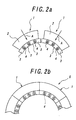
- the reference numeral 1 designates a sector mold.
- a tread ring is composed of a total of, for example, eight sector molds1 in a closing position.
- Each of the sector molds 1 comprises a segment 2 having a arched shape and, for example, four molding pieces 3 circumferentially aligned with each other and disposed on the inner surface side of the segments 2 to be able to move along a arched face.
- the molding pieces 3 of the sector molds are urged away from each other by a spring member 4 mounted therebetween.
- each of adjacent molding pieces 3 is specified its spacing limit location by a not-shown stopper or the like and the maximum spacing distance is, for example, 0.5 mm, so that there is no possibility of each molding piece 3 being excessively displaced to fall away from the segment 2.
- each of the molding pieces 3 of the sector molds1 is in the spacing position up to the limit location and each of the molding pieces 3 between the sector molds is also in the spacing position.
- each of the sector molds 1 is displaced radially inwardly, as shown by the arrow A in the figure, by closing the mold for vulcanizing and shaping a green tire, each of the molding pieces 3 between the adjacent sector molds tightly contacts with each other. Then, the clearances between the molding pieces 3 in the sector molds become smaller. Finally, the sector molds 1 form a tread ring 5 as shown in FIG. 2(b) at the completion of closing the molds and each of the molding pieces 3 in the sector molds is aligned with a clearance of less than 0.05 mm, which is the predefined gap.
- the embodiment can significantly enhance the efficiency of venting air as compared with the prior art by venting air in the mold through between the molding pieces having wider clearances especially after each of the molding pieces 3 of the adjacent sector molds 1 tightly contacts with each other and before the completion of closing the mold. This is more effective when air is forcibly vented by means of vacuum suction.
- the capacity of venting air can be significantly improved owing particularly to the large clearances of the molding pieces of each sector mold, so that the formation of bares or the like can be effectively prevented even though almost all or all of the vent holes is eliminated.
- the rubber is prevented from sticking between the molding pieces to assure the performance of venting air for a long period, so that a cycle of cleaning the mold can be largely extended, which enhances an operation efficiency of the mold.
Landscapes
- Engineering & Computer Science (AREA)
- Mechanical Engineering (AREA)
- Moulds For Moulding Plastics Or The Like (AREA)
- Heating, Cooling, Or Curing Plastics Or The Like In General (AREA)
Abstract
Description
Claims (2)
- A vulcanizing mold for a tire, comprising a tread ring for vulcanizing and shaping a tread of the tire, the tread ring comprising plural sector molds which are separately formed in the circumferential direction so as to be brought into surface contact with each other, wherein each of the sector molds comprises segments and plural movable molding pieces circumferentially aligned with each other and disposed on the inner surface side of the segments, and wherein the movable molding pieces of each sector mold are urged away from each other.
- The vulcanizing mold for a tire according to claim 1, wherein a relative clearance of the movable molding pieces is less than 0.05 mm in a position in which the sector molds form the tread ring.
Applications Claiming Priority (3)
| Application Number | Priority Date | Filing Date | Title |
|---|---|---|---|
| JP2001216641 | 2001-07-17 | ||
| JP2001216641 | 2001-07-17 | ||
| PCT/JP2002/007125 WO2003008169A1 (en) | 2001-07-17 | 2002-07-12 | Tire vulcanizing mold |
Publications (3)
| Publication Number | Publication Date |
|---|---|
| EP1415781A1 true EP1415781A1 (en) | 2004-05-06 |
| EP1415781A4 EP1415781A4 (en) | 2005-06-29 |
| EP1415781B1 EP1415781B1 (en) | 2006-10-18 |
Family
ID=19051096
Family Applications (1)
| Application Number | Title | Priority Date | Filing Date |
|---|---|---|---|
| EP02747663A Expired - Lifetime EP1415781B1 (en) | 2001-07-17 | 2002-07-12 | Tire vulcanizing mold |
Country Status (6)
| Country | Link |
|---|---|
| US (1) | US7025581B2 (en) |
| EP (1) | EP1415781B1 (en) |
| JP (1) | JP4454306B2 (en) |
| DE (1) | DE60215514T2 (en) |
| ES (1) | ES2274056T3 (en) |
| WO (1) | WO2003008169A1 (en) |
Cited By (7)
| Publication number | Priority date | Publication date | Assignee | Title |
|---|---|---|---|---|
| WO2008065463A1 (en) * | 2006-11-27 | 2008-06-05 | Pirelli Tyre S.P.A. | Apparatus for vulcanization and moulding of vehicles tyres |
| EP1825992A3 (en) * | 2006-02-22 | 2008-08-27 | Toyo Tire Rubber Co., Ltd. | Pneumatic tire and manufacturing method of the same |
| WO2010049960A1 (en) | 2008-10-31 | 2010-05-06 | Pirelli Tyre S.P.A. | Process and apparatus for moulding and vulcanisation of vehicle tyres |
| EP2296860A4 (en) * | 2008-06-30 | 2012-12-12 | Michelin Rech Tech | TIRE MOLD HAVING AN EFFECTIVE MOLD OPENING SYSTEM |
| CN104552671A (en) * | 2015-01-05 | 2015-04-29 | 山东豪迈机械科技股份有限公司 | Pattern block capable of regulating exhaust gap and collapsible mold for pore-free tyre |
| DE102005024069B4 (en) * | 2004-07-06 | 2017-12-28 | Toyo Tire & Rubber Co., Ltd. | mature form |
| EP4360843A4 (en) * | 2021-06-22 | 2024-10-30 | Bridgestone Corporation | Tire molding die and tire production method |
Families Citing this family (14)
| Publication number | Priority date | Publication date | Assignee | Title |
|---|---|---|---|---|
| JP4734907B2 (en) * | 2004-12-08 | 2011-07-27 | 横浜ゴム株式会社 | Tire molding die and tire manufacturing method |
| JP2007084035A (en) * | 2005-08-23 | 2007-04-05 | Toyo Tire & Rubber Co Ltd | Pneumatic tire and manufacturing method thereof |
| JP4707523B2 (en) * | 2005-09-30 | 2011-06-22 | アスモ株式会社 | Gear manufacturing method and gear manufacturing apparatus |
| JP2007290202A (en) * | 2006-04-24 | 2007-11-08 | Toyo Tire & Rubber Co Ltd | Tire molding die and pneumatic tire molded thereby |
| JP4780772B2 (en) * | 2006-06-13 | 2011-09-28 | 東洋ゴム工業株式会社 | Tire molding die and pneumatic tire molded thereby |
| JP4972425B2 (en) | 2007-02-13 | 2012-07-11 | 東洋ゴム工業株式会社 | Tire vulcanization mold and tire manufacturing method |
| US7540730B1 (en) | 2007-12-20 | 2009-06-02 | The Goodyear Tire & Rubber Company | Tire mold |
| US7800238B2 (en) * | 2008-06-27 | 2010-09-21 | Micron Technology, Inc. | Surface depressions for die-to-die interconnects and associated systems and methods |
| KR101006898B1 (en) | 2008-10-30 | 2011-01-14 | 한국타이어 주식회사 | Vulcanization device of automobile tire |
| JP4854766B2 (en) * | 2009-06-15 | 2012-01-18 | 東洋ゴム工業株式会社 | Mold for tire molding |
| US8731871B2 (en) | 2010-09-22 | 2014-05-20 | Bridgestone Americas Tire Operations, Llc | Tire mold design method to minimize unique annular mold parts |
| CN105324236B (en) * | 2013-06-28 | 2017-09-19 | 米其林集团总公司 | Tire-mold with improved durability |
| JP6130762B2 (en) * | 2013-09-19 | 2017-05-17 | 東洋ゴム工業株式会社 | Tire molding die and tire molding method |
| JP7577615B2 (en) * | 2021-06-22 | 2024-11-05 | 株式会社ブリヂストン | Tire molding mold and tire manufacturing method |
Family Cites Families (11)
| Publication number | Priority date | Publication date | Assignee | Title |
|---|---|---|---|---|
| US5120209A (en) * | 1989-12-29 | 1992-06-09 | Macmillan Kenneth T | Apparatus for molding tire treads |
| IT1240295B (en) * | 1990-04-13 | 1993-12-07 | Pirelli | MOLD AND METHOD FOR THE VULCANIZATION OF TIRES AND METHOD FOR MANUFACTURING MOLDS |
| JPH05220748A (en) * | 1992-02-13 | 1993-08-31 | Hashiba Tekko Kk | Mold for vulcanizing tire |
| JPH05220753A (en) * | 1992-02-13 | 1993-08-31 | Hashiba Tekko Kk | Method for manufacturing mold for tire vulcanization molding |
| ES2083223T3 (en) * | 1992-05-13 | 1996-04-01 | Sedepro | TIRE MOLD, AND TIRE MOLDING PROCEDURE. |
| FR2712229A1 (en) * | 1993-11-12 | 1995-05-19 | Sedepro | Tire mold, and tire molding method. |
| FR2759626A1 (en) * | 1997-02-19 | 1998-08-21 | Sedepro | TIRE MOLD |
| US6382943B1 (en) * | 1998-10-08 | 2002-05-07 | The Goodyear Tire & Rubber Company | Multiple insert tire mold and assembly method |
| WO2000020184A1 (en) * | 1998-10-08 | 2000-04-13 | The Goodyear Tire & Rubber Company | Multiple insert tire mold and assembly method |
| JP4353588B2 (en) * | 1999-07-07 | 2009-10-28 | 株式会社ブリヂストン | Mold for tire molding |
| JP2001232640A (en) * | 2000-02-21 | 2001-08-28 | Yokohama Rubber Co Ltd:The | Manufacturing method of tire vulcanizing mold |
-
2002
- 2002-07-12 EP EP02747663A patent/EP1415781B1/en not_active Expired - Lifetime
- 2002-07-12 WO PCT/JP2002/007125 patent/WO2003008169A1/en not_active Ceased
- 2002-07-12 ES ES02747663T patent/ES2274056T3/en not_active Expired - Lifetime
- 2002-07-12 JP JP2003513755A patent/JP4454306B2/en not_active Expired - Fee Related
- 2002-07-12 DE DE60215514T patent/DE60215514T2/en not_active Expired - Lifetime
- 2002-07-17 US US10/484,006 patent/US7025581B2/en not_active Expired - Lifetime
Cited By (11)
| Publication number | Priority date | Publication date | Assignee | Title |
|---|---|---|---|---|
| DE102005024069B4 (en) * | 2004-07-06 | 2017-12-28 | Toyo Tire & Rubber Co., Ltd. | mature form |
| EP1825992A3 (en) * | 2006-02-22 | 2008-08-27 | Toyo Tire Rubber Co., Ltd. | Pneumatic tire and manufacturing method of the same |
| CN101024368B (en) * | 2006-02-22 | 2010-05-26 | 东洋橡胶工业株式会社 | Pneumatic tire and its manufacturing method |
| EP2295230A1 (en) * | 2006-02-22 | 2011-03-16 | Toyo Tire & Rubber Co. Ltd. | Tire manufacturing method |
| WO2008065463A1 (en) * | 2006-11-27 | 2008-06-05 | Pirelli Tyre S.P.A. | Apparatus for vulcanization and moulding of vehicles tyres |
| CN101541518B (en) * | 2006-11-27 | 2012-07-18 | 倍耐力轮胎股份公司 | Apparatus for vulcanization and moulding of vehicles tyres |
| EP2296860A4 (en) * | 2008-06-30 | 2012-12-12 | Michelin Rech Tech | TIRE MOLD HAVING AN EFFECTIVE MOLD OPENING SYSTEM |
| WO2010049960A1 (en) | 2008-10-31 | 2010-05-06 | Pirelli Tyre S.P.A. | Process and apparatus for moulding and vulcanisation of vehicle tyres |
| CN104552671A (en) * | 2015-01-05 | 2015-04-29 | 山东豪迈机械科技股份有限公司 | Pattern block capable of regulating exhaust gap and collapsible mold for pore-free tyre |
| EP4360843A4 (en) * | 2021-06-22 | 2024-10-30 | Bridgestone Corporation | Tire molding die and tire production method |
| US12576606B2 (en) | 2021-06-22 | 2026-03-17 | Bridgestone Corporation | Mold for forming a tire and tire production method |
Also Published As
| Publication number | Publication date |
|---|---|
| ES2274056T3 (en) | 2007-05-16 |
| DE60215514D1 (en) | 2006-11-30 |
| EP1415781A4 (en) | 2005-06-29 |
| EP1415781B1 (en) | 2006-10-18 |
| US20040170715A1 (en) | 2004-09-02 |
| WO2003008169A1 (en) | 2003-01-30 |
| JP4454306B2 (en) | 2010-04-21 |
| DE60215514T2 (en) | 2007-08-09 |
| US7025581B2 (en) | 2006-04-11 |
| JPWO2003008169A1 (en) | 2004-11-04 |
Similar Documents
| Publication | Publication Date | Title |
|---|---|---|
| US7025581B2 (en) | Tire vulcanizing mold | |
| EP1676692A1 (en) | Methods for making a tread segment for use in a mold and a mold for vulcanizing tires | |
| CN101434113A (en) | Tyre forming die and tyre manufacturing method | |
| EP0468154B1 (en) | Improved tire mold, method and tire | |
| US4021168A (en) | Tire mold having washered nails inserted in the vents | |
| CN107206639B (en) | Tire molding mold and pneumatic tire | |
| JP2004136617A (en) | Tire molds and pneumatic tires | |
| US20140370137A1 (en) | Tire Vulcanization Mold and Manufacturing Method Therefor | |
| EP1238772A3 (en) | Tire vulcanizing mold | |
| EP1211055A3 (en) | Vulcanization process for pneumatic tire and mold therefor | |
| JP4236527B2 (en) | Tire molding die and tire molded using the tire molding die | |
| JP2005145024A (en) | Mold for molding tire | |
| CN101076438A (en) | Method and apparatus for manufacturing wheel tires | |
| CN108367521B (en) | Vulcanized mold with enhanced seal | |
| KR100426781B1 (en) | Sectional vulcanizing mold | |
| JP2002052537A (en) | Mold for vulcanizing pneumatic tires | |
| JP2005246803A (en) | Tire mold | |
| KR100878319B1 (en) | Tire Vulcanization Mold to Prevent Extraction | |
| JP6742594B2 (en) | Tire vulcanization mold | |
| JPH08216633A (en) | Tire bead structure and tire manufacturing method | |
| KR20000019857U (en) | Segment type curing mold with means of preventing pneumatic tire from having flash | |
| JP5607466B2 (en) | Tire vulcanization mold | |
| JP4052386B2 (en) | Tire mold and method of manufacturing pneumatic tire using the same | |
| JP2020097190A (en) | Tire manufacturing mold | |
| JPH05177644A (en) | Mold for pneumatic tire |
Legal Events
| Date | Code | Title | Description |
|---|---|---|---|
| PUAI | Public reference made under article 153(3) epc to a published international application that has entered the european phase |
Free format text: ORIGINAL CODE: 0009012 |
|
| 17P | Request for examination filed |
Effective date: 20040126 |
|
| AK | Designated contracting states |
Kind code of ref document: A1 Designated state(s): AT BE BG CH CY CZ DE DK EE ES FI FR GB GR IE IT LI LU MC NL PT SE SK TR |
|
| AX | Request for extension of the european patent |
Extension state: AL LT LV MK RO SI |
|
| A4 | Supplementary search report drawn up and despatched |
Effective date: 20050518 |
|
| GRAP | Despatch of communication of intention to grant a patent |
Free format text: ORIGINAL CODE: EPIDOSNIGR1 |
|
| RBV | Designated contracting states (corrected) |
Designated state(s): DE ES FR GB IT |
|
| GRAS | Grant fee paid |
Free format text: ORIGINAL CODE: EPIDOSNIGR3 |
|
| GRAA | (expected) grant |
Free format text: ORIGINAL CODE: 0009210 |
|
| AK | Designated contracting states |
Kind code of ref document: B1 Designated state(s): DE ES FR GB IT |
|
| PG25 | Lapsed in a contracting state [announced via postgrant information from national office to epo] |
Ref country code: IT Free format text: LAPSE BECAUSE OF FAILURE TO SUBMIT A TRANSLATION OF THE DESCRIPTION OR TO PAY THE FEE WITHIN THE PRESCRIBED TIME-LIMIT;WARNING: LAPSES OF ITALIAN PATENTS WITH EFFECTIVE DATE BEFORE 2007 MAY HAVE OCCURRED AT ANY TIME BEFORE 2007. THE CORRECT EFFECTIVE DATE MAY BE DIFFERENT FROM THE ONE RECORDED. Effective date: 20061018 |
|
| REG | Reference to a national code |
Ref country code: GB Ref legal event code: FG4D |
|
| REF | Corresponds to: |
Ref document number: 60215514 Country of ref document: DE Date of ref document: 20061130 Kind code of ref document: P |
|
| REG | Reference to a national code |
Ref country code: ES Ref legal event code: FG2A Ref document number: 2274056 Country of ref document: ES Kind code of ref document: T3 |
|
| ET | Fr: translation filed | ||
| PLBE | No opposition filed within time limit |
Free format text: ORIGINAL CODE: 0009261 |
|
| STAA | Information on the status of an ep patent application or granted ep patent |
Free format text: STATUS: NO OPPOSITION FILED WITHIN TIME LIMIT |
|
| 26N | No opposition filed |
Effective date: 20070719 |
|
| PGFP | Annual fee paid to national office [announced via postgrant information from national office to epo] |
Ref country code: ES Payment date: 20090804 Year of fee payment: 8 |
|
| PGFP | Annual fee paid to national office [announced via postgrant information from national office to epo] |
Ref country code: GB Payment date: 20090708 Year of fee payment: 8 |
|
| GBPC | Gb: european patent ceased through non-payment of renewal fee |
Effective date: 20100712 |
|
| PG25 | Lapsed in a contracting state [announced via postgrant information from national office to epo] |
Ref country code: GB Free format text: LAPSE BECAUSE OF NON-PAYMENT OF DUE FEES Effective date: 20100712 |
|
| REG | Reference to a national code |
Ref country code: ES Ref legal event code: FD2A Effective date: 20110818 |
|
| PG25 | Lapsed in a contracting state [announced via postgrant information from national office to epo] |
Ref country code: ES Free format text: LAPSE BECAUSE OF NON-PAYMENT OF DUE FEES Effective date: 20100713 |
|
| PGFP | Annual fee paid to national office [announced via postgrant information from national office to epo] |
Ref country code: IT Payment date: 20120714 Year of fee payment: 11 Ref country code: FR Payment date: 20120719 Year of fee payment: 11 Ref country code: DE Payment date: 20120704 Year of fee payment: 11 |
|
| REG | Reference to a national code |
Ref country code: FR Ref legal event code: ST Effective date: 20140331 |
|
| PG25 | Lapsed in a contracting state [announced via postgrant information from national office to epo] |
Ref country code: DE Free format text: LAPSE BECAUSE OF NON-PAYMENT OF DUE FEES Effective date: 20140201 |
|
| REG | Reference to a national code |
Ref country code: DE Ref legal event code: R119 Ref document number: 60215514 Country of ref document: DE Effective date: 20140201 |
|
| PG25 | Lapsed in a contracting state [announced via postgrant information from national office to epo] |
Ref country code: IT Free format text: LAPSE BECAUSE OF NON-PAYMENT OF DUE FEES Effective date: 20130712 Ref country code: FR Free format text: LAPSE BECAUSE OF NON-PAYMENT OF DUE FEES Effective date: 20130731 |