EP1415739A1 - A Method for Producing a Freeze-Cast Substrate - Google Patents
A Method for Producing a Freeze-Cast Substrate Download PDFInfo
- Publication number
- EP1415739A1 EP1415739A1 EP20030103586 EP03103586A EP1415739A1 EP 1415739 A1 EP1415739 A1 EP 1415739A1 EP 20030103586 EP20030103586 EP 20030103586 EP 03103586 A EP03103586 A EP 03103586A EP 1415739 A1 EP1415739 A1 EP 1415739A1
- Authority
- EP
- European Patent Office
- Prior art keywords
- mould
- freeze
- temperature
- substrate
- slurry
- Prior art date
- Legal status (The legal status is an assumption and is not a legal conclusion. Google has not performed a legal analysis and makes no representation as to the accuracy of the status listed.)
- Granted
Links
Images

Classifications
-
- B—PERFORMING OPERATIONS; TRANSPORTING
- B22—CASTING; POWDER METALLURGY
- B22C—FOUNDRY MOULDING
- B22C9/00—Moulds or cores; Moulding processes
- B22C9/12—Treating moulds or cores, e.g. drying, hardening
- B22C9/126—Hardening by freezing
-
- B—PERFORMING OPERATIONS; TRANSPORTING
- B33—ADDITIVE MANUFACTURING TECHNOLOGY
- B33Y—ADDITIVE MANUFACTURING, i.e. MANUFACTURING OF THREE-DIMENSIONAL [3D] OBJECTS BY ADDITIVE DEPOSITION, ADDITIVE AGGLOMERATION OR ADDITIVE LAYERING, e.g. BY 3D PRINTING, STEREOLITHOGRAPHY OR SELECTIVE LASER SINTERING
- B33Y80/00—Products made by additive manufacturing
Definitions
- This invention relates generally to producing a freeze-cast substrate and in particular to a method for producing a freeze-cast substrate with minimal distortion.
- Spray forming techniques for producing steel prototype tooling, such as dies or moulds, are commonly utilized to make steel tooling.
- the typical spray forming technique includes the following steps:
- the casting step is commonly accomplished through a freeze-casting process.
- One typical freeze-casting process includes the following steps:
- the method can produce warping and distortion in the spraying pattern. Consequently, the metal deposit may not accurately reflect the master pattern. In extreme cases, the warping and distortion may be so pronounced that the metal deposit is rendered unusable as a steel prototype tool.
- a method for producing a freeze-cast substrate characterised in that the method comprises introducing a slurry into a mould unit comprised of a mould contained within a substrate receptacle and lowering the temperature of the slurry to freeze the slurry and form a freeze-cast substrate while controlling temperature gradients within the mould unit to minimize distortion in the freeze-cast substrate.
- the control of the temperature within the mould unit may also control the temperature of the slurry in the mould unit.
- the lowering step may include placing insulation material around at least a portion of the substrate receptacle to minimize distortion in the freeze-cast substrate by controlling temperature gradients within the mould unit.
- the insulating material may have a thermal conductivity of about 0.04 w/m K or less.
- the insulating material may be a fibreglass insulating material.
- the rate at which the temperature is lowered may be controlled to minimize temperature gradients in the mould unit.
- the method may include abruptly decreasing the temperature of the mould unit from room temperature to a sub-chilling temperature.
- a chilling apparatus may be provided for the lowering step.
- the chilling apparatus may be a freezer.
- the chilling apparatus may include a temperature controller for adjusting the temperature within the chilling apparatus.
- Metallic particles may be sprayed onto the freeze-cast substrate.
- the metallic particles may be sprayed onto the freeze-cast substrate by a spray forming technique.
- the spray forming technique may be selected from the group consisting of cold spraying, flame powder, flame wire, arc-spraying, plasma-spraying, high-energy plasma-spraying, vacuum plasma-spraying, detonation, and high-velocity oxyfuel.
- a mould unit for producing a freeze-cast substrate from a slurry characterised in that the mould unit comprises a mould, a substrate receptacle having four interconnected side panels, each having an inner surface and outer surface and a layer of insulating material provided around at least a portion of the outer surfaces of the side panels for minimizing distortion in the freeze-cast substrate by controlling temperature gradients within the mould unit.
- the mould may have a lower surface which is supported by a base panel of the substrate receptacle.
- the insulating material may overlie the base panel.
- the mould may have an upper surface, a lower surface
- the substrate receptacle may have first and second panel pairs arranged perpendicular to one another which are interconnected and each panel may have an inner and outer surface and at least two ribs may be connected to the first panel pair, the ribs being spaced apart from each other and from the second panel pair to form cavities and are arranged to receive the lower surface of the mould so as to support the mould and insulating material is provided in at least a portion of the cavities for minimizing distortion in the freeze-cast substrate by controlling temperature gradients within the mould unit.
- the insulating material may have a thermal conductivity of les than 0.04 w/m K.
- the insulting material may be a fibreglass insulating material.
- a method of the present invention generally comprises at least two basic steps:
- mould unit 10 is comprised of mould 12 and substrate receptacle 14.
- the mould 12 contains a master pattern representative of the tool to be produced and is preferably constructed of polymeric material.
- the master pattern can be created using solid-free form fabrication techniques controlled by a CAD/CAM model. Free-formed fabrication can comprise stereolithography, cubital, laminated or foam object manufacturing, 3-D printing and stratified extrusion. Stereolithography is preferred since it creates a pattern directly from a vat of liquid photocurable polymer through selective solidification using a scanner laser beam.
- the master pattern can also be milled, or formed from wood, metal, laminate materials, and Ren board.
- the mould 12 is defined in part by a base surface 16 and an upper surface 18 and is placed in the substrate receptacle 14.
- the substrate receptacle 14 has a receiving surface 20 which has essentially the same basic contour as the base surface 16 of the mould 12 for supporting the mould 12.
- the substrate receptacle 14 is constructed of four side panels and a bottom panel which contains receiving surface 20. The panels are fastened together to form the substrate receptacle 14 with a plurality of nails or other suitable fasteners.
- an alternative mould 22 that can be constructed in accordance with the present invention is defined in part by contoured base surface 24 and upper surface 26 which contains the master pattern.
- the shape of the contoured base surface 24 in this case generally reflects the shape of upper surface 26.
- a number of ribs 28 are fastened to a pair of opposing side panels of the substrate receptacle 14 to receive the contoured base surface 24 and support the mould 22.
- the ribs 28 are fastened to the pair of opposing side panels with nails or other suitable fasteners and are constructed of plywood, plastic, etc.
- the substrate receptacle 14 is constructed without a bottom panel for use with mould 22 because ribs 28 function to sufficiently support mould 22 without receiving surface 20. It should be understood that the bottom panel can be used for additional support.
- a slurry 30 is introduced into the substrate receptacle 14 about the master pattern at room temperature.
- the slurry 30 is introduced by pouring and can be made of any suitable ceramic known in the art.
- Suitable ceramics include aluminium oxide or silica core sand. Suitable ceramics should provides an excellent surface finish, good thermal shock resistance at 980 to 1320°C (1800-2400°F), a compressive strength of at least about 6.2MPa (9000 psi) and low shrinkage along with low thermal expansion.
- the slurry 30 is preferably comprised of alumina and aqueous silica, otherwise referred to as silica sol.
- the alumina can act as a filler material.
- filler materials can be used as long as they are thermally stable and do not react with the silica sol.
- the slurry 30 After introducing the slurry 30 into the substrate receptacle 14, the slurry 30 is chilled so that the temperature is lowered to freeze it and form a freeze-cast substrate.
- a preferred process of chilling slurry 30 includes placing mould unit 10 in a chilling apparatus and setting the chilling apparatus to a chilling temperature to freeze slurry 30.
- the chilling apparatus is preferably an upright walk-in freezer. Any chilling apparatus capable of maintaining temperatures from about -30°C to about 0°C can be used to freeze slurry 30.
- the chilling apparatus can include a temperature controller, such devices are manufactured by Hanse Industries of Allegan, Michigan.
- the freeze-cast substrate is then removed from substrate receptacle 14.
- a release agent such as silicone or a wax is preferably applied to the upper surface of the mould and the inside of the casting receptacle before introducing slurry 30 to help facilitate the removal of the freeze-cast substrate 34 from the substrate receptacle 14 and the mould 12 or 22.
- freeze-cast substrate After the freeze-cast substrate is removed from the substrate receptacle 14, it is heated in a furnace to drive off any free liquid in the ceramic.
- the chilling temperature can be set to about -30°C.
- the temperature of base surface 16 of mould 12 can be about 20°C (i.e., room temperature)
- the temperature of first mould point 36 located about 2 inches below exposed surface 37 of slurry 30 on the upper surface 18 of mould 12 can be about 20°C (i.e., room temperature)
- the temperature of second mould point 38 located about 10 inches below exposed surface 37 of slurry 30 on the upper surface 18 of mould 12 can be about 20°C (i.e., room temperature).
- the temperature of base surface 16 of mould 12 can be about -20°C.
- the temperature of first mould point 36 can be about -5°C as heat escapes from first mould point 36 in order to reach the temperature of the surrounding frozen slurry.
- the temperature of second mould point 38 can be about 5°C since heat escapes from second mould point 38 in order to reach the temperature of the surrounding chilled liquid slurry.
- the temperature of base surface 16 of mould 12 can be about -30°C.
- the temperature of first mould point 36 can be about -5°C, i.e., the temperature of the frozen slurry surrounding first mould point 36.
- the temperature of the second mould point 38 can be about -5°C since the slurry surrounding second mould point 38 can be frozen by time 2.
- a temperature gradient of 25°C exists between second mould point 38 and base surface 16 at time 1 and at time 2, a temperature gradient of 25°C exists between first mould point 36 and base surface 16.
- the stresses are relieved through movement and/or dimensional change within the mould and/or slurry, i.e., portions of the mould and/or slurry expand and/or contract.
- This expansion and/or contraction can cause warping and/or distortion of the upper surface of mould 12 or 22 which contains the master pattern of the tool to be produced. Consequently, the freeze-cast substrate can be warped and/or distorted, leading to imperfections in the tool produced by depositing metallic particles onto the freeze-cast substrate.
- the amount of distortion in the freeze-cast substrate can be minimized by controlling temperature gradients within the mould unit.
- the temperature gradients By controlling the temperature gradients, the thermal stresses are minimized, and, therefore, less warping and/or distortion occurs within the mould and/or the slurry.
- temperature gradients Depending on various operating parameters, i.e., mould size, mould composition, slurry composition, chilling temperature, temperature gradients of about 0°C to about 25°C can efficiently minimize the amount of distortion.
- a preferred method of controlling temperature gradients includes providing insulation material 40 around the mould 12 or 22 by placing material 40 around mould unit 10.
- Suitable insulating materials include fibreglass, cork, and rock wool.
- the insulating material has a thermal conductivity of about 0.04 w/m K or less.
- insulating material 40 is comprised of a fibreglass insulating material.
- MIRAFLEX R-25, PINK R-13, or PINK R-19 fibreglass insulation available from Owen Corning of Toledo, Ohio, can be utilized. It should be understood that other insulating materials can be used as long as they effectively reduce the transfer of heat.
- Insulating material can be placed around at least a portion of the side panels of substrate receptacle 14.
- Insulating material 40 can be stapled, nailed, taped, or glued to the four side panels. Insulating material 40 can also be leaned up against the side panels. Preferably, at least one layer of insulating material is secured to the external surfaces of the side panels with tape. Additionally, insulating material 40 can be placed beneath bottom surface of casting receptacle 14.
- the thickness of the insulating material is preferably about 2 inches to about 12 inches, and most preferably about 4 inches to about 6 inches (referring to uncompressed thickness with respect to bottom surface).
- the casting receptacle can be placed on a false bottom which can reduce compression of the insulating material placed beneath mould unit 10. In the case of mould 22, insulating material can be placed in cavities 41 between ribs 28.
- Insulating material 40 reduces the transfer of heat from the side panels and/or the bottom surface of casting receptacle 14 and, therefore, reduces the formation of thermal stresses within the mould and slurry. Thermal stresses may form about exposed surface 41 since most of the heat within the mould and slurry will escape upward through this surface. However, any resulting distortion has minimal, if any, effect on the quality of the tool produced since the exposed surface does not receive the metallic coating (i.e., the exposed surface is the least critical surface).
- Another method of controlling temperature gradients includes controlling the freezing rate that is to say the rate of lowering the temperature of the mould unit.
- the freezing rate can be controlled by utilizing a temperature controller that controls the temperature of the chilling apparatus, i.e., set to achieve a specified ramp rate.
- lowering the temperature of the mould unit can be conducted in a two-stage process comprised of (1) a pre-chilling stage and (2) a hard-freeze stage.
- the controller temperature during the pre-chill stage can be between about 0°C and about 3°C, and preferably about 2°C.
- the controller temperature during the hard-freeze stage can be between about -20°C and about -50°C, and preferably about -40°C.
- the duration of stages (1) and (2) can depend on a number of variables, which include, but are not limited to, mould material, casting receptacle material, and mould size. To account for these variations, temperature readings made by thermocouples during freezing can be used to determine the duration of stages (1) and (2). The temperature readings can be directly fed back to the temperature controller that controls the temperature within the chilling apparatus. At least one thermocouple can be placed in the mould, preferably at about the centre point of one quadrant of the mould. At least one thermocouple can be placed in the slurry at mid-depth where the slurry is the deepest.
- the temperature controller can initially set the chilling apparatus to about 2°C to begin the pre-chilling stage.
- the pre-chilling stage lasts until the at least two thermocouples indicate that this temperature has been reached at most locations within the slurry and mould.
- the temperature controller can set the chilling apparatus to -40°C to begin the hard-freeze stage.
- the hard-freeze stage can end and extraction of freeze-cast substrate can be accomplished.
- an intermediate stage can be added for thermally difficult moulds (i.e., moulds with low thermal conductivities and/or high coefficients of thermal expansion) which have a tendency to distort.
- the intermediate stage begins once the at least two thermocouples indicate that the pre-chilling temperature has been reached at locations within the mould and slurry.
- the temperature of the chilling apparatus during the intermediate stage is preferably -8°C.
- the intermediate stage lasts until the at least two thermocouples indicate that this temperature has been reached at most locations within the mould and slurry.
- Another method of controlling temperature gradients includes abruptly decreasing temperature of the chilling apparatus to a sub-chilling temperature to abruptly freeze slurry 30.
- liquid nitrogen can be introduced into the freezing apparatus to set the chilling apparatus to the sub-chilling temperature.
- a preferred sub-chilling temperature is about -70°C.
- liquid nitrogen can be poured directly onto the exposed slurry surface 37. After about one minute, the freeze-cast substrate, i.e., the frozen slurry, is removed from the mould and casting receptacle.
- spray forming can refer to any technique used to deposit metal particles upon a substrate, i.e., thermal spraying, and cold spraying.
- Spray forming techniques that can be used in accord with the present invention include, but are not limited to spray-rolling, spray-forging, centrifugal spray-casting, spray-casting, spray-peening, splat-coating, particle composite deposition, roller atomizing, modified arc spray, and modified plasma-spraying.
- thermal spray gun(s) 42 shown schematically in Figure 3 are utilized to spray metallic particles 44 onto the spraying pattern of freeze-cast substrate 36.
- the thermal spray gun 42 can be of the oxy-acetylene flame type in which a wire or powder metal is fed, a plasma-type into which powder metal is fed, or preferably one or two wire arc type, in which the tip of the wires is fed into the arc.
- Cold spraying guns capable of impact fusion could be used in place of thermal spray guns to spray metallic particles onto the freeze-cast substrate.
- high-energy plasma-spraying, vacuum plasma-spraying, detonation, and high-velocity oxyfuel techniques can be utilized.
- an electric arc is generated in a zone between two consumable wire electrodes. As the electrodes melt, the arc is maintained by continuously feeding the electrodes into the arc zone. The metal at the electrode tips is atomized by a blast of generally cold compressed gas. The atomized metal is then propelled by the gas jet to a substrate forming a deposit thereon.
- a single wire is fed either through the central axis of the torch or is fed at an acute angle into a plasma stream that is generated internally within the torch.
- the single wire acts as a consumable electrode that is fed into the arc chamber.
- the arc is established between the cathode of the plasma torch and the single wire as an anode, thereby melting the tip of the wire.
- Gas is fed into the arc chamber, coaxially to the cathode, where it is expanded by the electric arc to cause a highly heated gas stream (carrying metal droplets from the electrode tip) to flow through the nozzle.
- a further higher temperature gas flow may be used to shroud or surround the spray of molten metal so that droplets are subjected to further atomization and acceleration.
- wire arc torch guns may be utilized that use a transferred-arc plasma whereby an initial arc is struck between a cathode and a nozzle surrounding the cathode.
- the plasma created from such arc is transferred to a secondary anode (outside the gun nozzle) in the form of a single or double wire feedstock, causing melting of the tip of such wire feedstock.
- a thermal spray gun 42 has a gun tip 46 which is oriented along an axis 48 perpendicular to the general planar extent of the base of the freeze-case substrate.
- the thermal spray gun 42 has a power supply 50 operated at about 30 volts.
- Thermal spray gun 42 is supplied with a high pressure gas from their respective supplies consisting of nitrogen, air, or a mixture thereof, at a pressure of about 40 to 120 psi, such gas being utilized to affect the atomization of the wire droplets.
- the gun 42 may be moved robotically, such as by robots 52 and the freeze-cast substrate 36 may be mounted on a turntable 54 and rotated by a motor to achieve relative movement between the spray pattern of the guns and the spraying pattern. Repeated passes of the spray material will deposit a bulk deposit having a thickness of at least about 2.54mm (0.1 inches), and preferably between about 12.5mm (0.5 inches) and about 50mm (2 inches) on surface 26.
- the thermal spraying step preferably lasts for about three hours, and results in deposits 46 having a thickness of between about 0.5 to about 2.0 inches for deposits of about 2 feet by 2 feet. Larger sized deposits may require thicker sections and more passes.
Landscapes
- Engineering & Computer Science (AREA)
- Mechanical Engineering (AREA)
- Moulds For Moulding Plastics Or The Like (AREA)
- Coating By Spraying Or Casting (AREA)
Abstract
Description
- This invention relates generally to producing a freeze-cast substrate and in particular to a method for producing a freeze-cast substrate with minimal distortion.
- Spray forming techniques for producing steel prototype tooling, such as dies or moulds, are commonly utilized to make steel tooling. The typical spray forming technique includes the following steps:
- (1) casting a ceramic substrate containing a spraying pattern about a mould containing a master pattern of the tool to be produced;
- (2) spraying metallic particles onto the ceramic substrate containing the spraying pattern;
- (3) allowing the sprayed metallic particles to form a metal deposit having the general shape of the master pattern; and
- (4) separating the metal deposit from the ceramic substrate.
-
- The casting step is commonly accomplished through a freeze-casting process. One typical freeze-casting process includes the following steps:
- (1) pouring a slurry into the mould containing the master pattern,
- (2) lowering the temperature of the slurry to freeze the slurry and form a freeze-cast substrate containing the spraying pattern,
- (3) extracting the freeze-cast substrate from the mould,
- (4) thawing the freeze-cast substrate, and
- (5) drying the freeze-cast substrate during the firing cycle.
-
- While the above method of freeze-casting produces acceptable freeze-cast substrates, the method can produce warping and distortion in the spraying pattern. Consequently, the metal deposit may not accurately reflect the master pattern. In extreme cases, the warping and distortion may be so pronounced that the metal deposit is rendered unusable as a steel prototype tool.
- It is an object of the present invention to provide a method of producing a freeze-cast substrate that minimises the amount of distortion the freeze-cast substrate.
- According to a first aspect of the invention there is provided a method for producing a freeze-cast substrate, characterised in that the method comprises introducing a slurry into a mould unit comprised of a mould contained within a substrate receptacle and lowering the temperature of the slurry to freeze the slurry and form a freeze-cast substrate while controlling temperature gradients within the mould unit to minimize distortion in the freeze-cast substrate.
- The control of the temperature within the mould unit may also control the temperature of the slurry in the mould unit.
- The lowering step may include placing insulation material around at least a portion of the substrate receptacle to minimize distortion in the freeze-cast substrate by controlling temperature gradients within the mould unit.
- The insulating material may have a thermal conductivity of about 0.04 w/m K or less.
- The insulating material may be a fibreglass insulating material.
- Alternatively, the rate at which the temperature is lowered may be controlled to minimize temperature gradients in the mould unit.
- The method may include abruptly decreasing the temperature of the mould unit from room temperature to a sub-chilling temperature.
- A chilling apparatus may be provided for the lowering step.
- The chilling apparatus may be a freezer.
- The chilling apparatus may include a temperature controller for adjusting the temperature within the chilling apparatus.
- Metallic particles may be sprayed onto the freeze-cast substrate.
- The metallic particles may be sprayed onto the freeze-cast substrate by a spray forming technique. The spray forming technique may be selected from the group consisting of cold spraying, flame powder, flame wire, arc-spraying, plasma-spraying, high-energy plasma-spraying, vacuum plasma-spraying, detonation, and high-velocity oxyfuel.
- According to a second aspect of the invention there is provided a mould unit for producing a freeze-cast substrate from a slurry characterised in that the mould unit comprises a mould, a substrate receptacle having four interconnected side panels, each having an inner surface and outer surface and a layer of insulating material provided around at least a portion of the outer surfaces of the side panels for minimizing distortion in the freeze-cast substrate by controlling temperature gradients within the mould unit.
- The mould may have a lower surface which is supported by a base panel of the substrate receptacle.
- The insulating material may overlie the base panel.
- The mould may have an upper surface, a lower surface, the substrate receptacle may have first and second panel pairs arranged perpendicular to one another which are interconnected and each panel may have an inner and outer surface and at least two ribs may be connected to the first panel pair, the ribs being spaced apart from each other and from the second panel pair to form cavities and are arranged to receive the lower surface of the mould so as to support the mould and insulating material is provided in at least a portion of the cavities for minimizing distortion in the freeze-cast substrate by controlling temperature gradients within the mould unit.
- The insulating material may have a thermal conductivity of les than 0.04 w/m K.
- The insulting material may be a fibreglass insulating material.
- The invention will now be described by way of example with reference to the accompanying drawing of which:-
- Fig.1 is a schematic illustration of a preferred mould unit of the present invention used in a freeze-casting process of the present invention;
- Fig.2 is a schematic illustration of another preferred mould unit of the present invention used in a freeze-casting process of the present invention; and
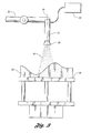
- Fig.3 is a schematic illustration of an apparatus used in a spray forming process of the present invention.
-
- As required, detailed embodiments of the present invention are disclosed herein. However, it is to be understood that the disclosed embodiments are merely exemplary of the invention that may be embodied in various and alternative forms. The figures are not necessarily to scale and some features may be exaggerated or minimized to show details of particular components. Therefore, specific structural and functional details disclosed herein are not to be interpreted as limiting, but merely as a representative basis for teaching one skilled in the art to variously employ the present invention.
- A method of the present invention generally comprises at least two basic steps:
- (a) introducing a slurry into a mould unit comprised of a mould contained within a casting receptacle, and
- (b) lowering the temperature of the slurry to freeze the slurry and form a freeze-cast substrate while controlling temperature gradients within the mould unit to minimize distortion in the freeze-cast substrate.
-
- Referring to Figure 1,
mould unit 10 is comprised ofmould 12 andsubstrate receptacle 14. Themould 12 contains a master pattern representative of the tool to be produced and is preferably constructed of polymeric material. The master pattern can be created using solid-free form fabrication techniques controlled by a CAD/CAM model. Free-formed fabrication can comprise stereolithography, cubital, laminated or foam object manufacturing, 3-D printing and stratified extrusion. Stereolithography is preferred since it creates a pattern directly from a vat of liquid photocurable polymer through selective solidification using a scanner laser beam. The master pattern can also be milled, or formed from wood, metal, laminate materials, and Ren board. - The
mould 12 is defined in part by abase surface 16 and anupper surface 18 and is placed in thesubstrate receptacle 14. Thesubstrate receptacle 14 has areceiving surface 20 which has essentially the same basic contour as thebase surface 16 of themould 12 for supporting themould 12. - The
substrate receptacle 14 is constructed of four side panels and a bottom panel which containsreceiving surface 20. The panels are fastened together to form thesubstrate receptacle 14 with a plurality of nails or other suitable fasteners. - Referring to Figure 2, an
alternative mould 22 that can be constructed in accordance with the present invention is defined in part bycontoured base surface 24 andupper surface 26 which contains the master pattern. The shape of thecontoured base surface 24 in this case generally reflects the shape ofupper surface 26. A number ofribs 28 are fastened to a pair of opposing side panels of thesubstrate receptacle 14 to receive thecontoured base surface 24 and support themould 22. Theribs 28 are fastened to the pair of opposing side panels with nails or other suitable fasteners and are constructed of plywood, plastic, etc. - The
substrate receptacle 14 is constructed without a bottom panel for use withmould 22 because ribs 28 function to sufficiently supportmould 22 without receivingsurface 20. It should be understood that the bottom panel can be used for additional support. - Referring to Figures 1 and 2, a
slurry 30 is introduced into thesubstrate receptacle 14 about the master pattern at room temperature. Theslurry 30 is introduced by pouring and can be made of any suitable ceramic known in the art. - Examples of suitable ceramics include aluminium oxide or silica core sand. Suitable ceramics should provides an excellent surface finish, good thermal shock resistance at 980 to 1320°C (1800-2400°F), a compressive strength of at least about 6.2MPa (9000 psi) and low shrinkage along with low thermal expansion. The
slurry 30 is preferably comprised of alumina and aqueous silica, otherwise referred to as silica sol. The alumina can act as a filler material. - It should be understood that other filler materials can be used as long as they are thermally stable and do not react with the silica sol.
- After introducing the
slurry 30 into thesubstrate receptacle 14, theslurry 30 is chilled so that the temperature is lowered to freeze it and form a freeze-cast substrate. - A preferred process of chilling
slurry 30 includes placingmould unit 10 in a chilling apparatus and setting the chilling apparatus to a chilling temperature to freezeslurry 30. The chilling apparatus is preferably an upright walk-in freezer. Any chilling apparatus capable of maintaining temperatures from about -30°C to about 0°C can be used to freezeslurry 30. The chilling apparatus can include a temperature controller, such devices are manufactured by Hanse Industries of Allegan, Michigan. -
Slurry 30, after it freezes, forms the freeze-cast substrate which has aperipheral surface 32, which closely resembles the spraying pattern. - The freeze-cast substrate is then removed from
substrate receptacle 14. A release agent, such as silicone or a wax is preferably applied to the upper surface of the mould and the inside of the casting receptacle before introducingslurry 30 to help facilitate the removal of the freeze-cast substrate 34 from thesubstrate receptacle 14 and themould - After the freeze-cast substrate is removed from the
substrate receptacle 14, it is heated in a furnace to drive off any free liquid in the ceramic. - During the chilling of
mould base surface 16 ofmould 12 can be about 20°C (i.e., room temperature), the temperature offirst mould point 36 located about 2 inches below exposedsurface 37 ofslurry 30 on theupper surface 18 ofmould 12 can be about 20°C (i.e., room temperature), and the temperature ofsecond mould point 38 located about 10 inches below exposedsurface 37 ofslurry 30 on theupper surface 18 ofmould 12 can be about 20°C (i.e., room temperature). - After the mould has been exposed to the chilling temperature for a period of time (time 1), the temperature of
base surface 16 ofmould 12 can be about -20°C. The temperature offirst mould point 36 can be about -5°C as heat escapes fromfirst mould point 36 in order to reach the temperature of the surrounding frozen slurry. The temperature ofsecond mould point 38 can be about 5°C since heat escapes fromsecond mould point 38 in order to reach the temperature of the surrounding chilled liquid slurry. - After the mould has been exposed to the chilling temperature for a period of time longer than time 1 (time 2), the temperature of
base surface 16 ofmould 12 can be about -30°C. The temperature offirst mould point 36 can be about -5°C, i.e., the temperature of the frozen slurry surroundingfirst mould point 36. The temperature of thesecond mould point 38 can be about -5°C since the slurry surroundingsecond mould point 38 can be frozen by time 2. - According to this example, a temperature gradient of 25°C exists between
second mould point 38 andbase surface 16 at time 1 and at time 2, a temperature gradient of 25°C exists betweenfirst mould point 36 andbase surface 16. - Temperature gradients form between points in the slurry, as well and these temperature gradients can cause thermal stresses within the mould and/or slurry. The stresses are relieved through movement and/or dimensional change within the mould and/or slurry, i.e., portions of the mould and/or slurry expand and/or contract. This expansion and/or contraction can cause warping and/or distortion of the upper surface of
mould - According to one embodiment of the present invention, the amount of distortion in the freeze-cast substrate can be minimized by controlling temperature gradients within the mould unit. By controlling the temperature gradients, the thermal stresses are minimized, and, therefore, less warping and/or distortion occurs within the mould and/or the slurry. Depending on various operating parameters, i.e., mould size, mould composition, slurry composition, chilling temperature, temperature gradients of about 0°C to about 25°C can efficiently minimize the amount of distortion.
- A preferred method of controlling temperature gradients includes providing
insulation material 40 around themould material 40 aroundmould unit 10. - Examples of suitable insulating materials include fibreglass, cork, and rock wool. Preferably, the insulating material has a thermal conductivity of about 0.04 w/m K or less. Preferably, insulating
material 40 is comprised of a fibreglass insulating material. For example, MIRAFLEX R-25, PINK R-13, or PINK R-19 fibreglass insulation available from Owen Corning of Toledo, Ohio, can be utilized. It should be understood that other insulating materials can be used as long as they effectively reduce the transfer of heat. - Insulating material can be placed around at least a portion of the side panels of
substrate receptacle 14. Insulatingmaterial 40 can be stapled, nailed, taped, or glued to the four side panels. Insulatingmaterial 40 can also be leaned up against the side panels. Preferably, at least one layer of insulating material is secured to the external surfaces of the side panels with tape. Additionally, insulatingmaterial 40 can be placed beneath bottom surface of castingreceptacle 14. The thickness of the insulating material is preferably about 2 inches to about 12 inches, and most preferably about 4 inches to about 6 inches (referring to uncompressed thickness with respect to bottom surface). The casting receptacle can be placed on a false bottom which can reduce compression of the insulating material placed beneathmould unit 10. In the case ofmould 22, insulating material can be placed incavities 41 betweenribs 28. - Insulating
material 40 reduces the transfer of heat from the side panels and/or the bottom surface of castingreceptacle 14 and, therefore, reduces the formation of thermal stresses within the mould and slurry. Thermal stresses may form about exposedsurface 41 since most of the heat within the mould and slurry will escape upward through this surface. However, any resulting distortion has minimal, if any, effect on the quality of the tool produced since the exposed surface does not receive the metallic coating (i.e., the exposed surface is the least critical surface). - Another method of controlling temperature gradients includes controlling the freezing rate that is to say the rate of lowering the temperature of the mould unit. The freezing rate can be controlled by utilizing a temperature controller that controls the temperature of the chilling apparatus, i.e., set to achieve a specified ramp rate.
- For example, lowering the temperature of the mould unit can be conducted in a two-stage process comprised of (1) a pre-chilling stage and (2) a hard-freeze stage.
- The controller temperature during the pre-chill stage can be between about 0°C and about 3°C, and preferably about 2°C. The controller temperature during the hard-freeze stage can be between about -20°C and about -50°C, and preferably about -40°C. The duration of stages (1) and (2) can depend on a number of variables, which include, but are not limited to, mould material, casting receptacle material, and mould size. To account for these variations, temperature readings made by thermocouples during freezing can be used to determine the duration of stages (1) and (2). The temperature readings can be directly fed back to the temperature controller that controls the temperature within the chilling apparatus. At least one thermocouple can be placed in the mould, preferably at about the centre point of one quadrant of the mould. At least one thermocouple can be placed in the slurry at mid-depth where the slurry is the deepest.
- According to a preferred embodiment, the temperature controller can initially set the chilling apparatus to about 2°C to begin the pre-chilling stage. The pre-chilling stage lasts until the at least two thermocouples indicate that this temperature has been reached at most locations within the slurry and mould. At this point, the temperature controller can set the chilling apparatus to -40°C to begin the hard-freeze stage. When the slurry is hard and frozen, the hard-freeze stage can end and extraction of freeze-cast substrate can be accomplished.
- It should be understood that an intermediate stage can be added for thermally difficult moulds (i.e., moulds with low thermal conductivities and/or high coefficients of thermal expansion) which have a tendency to distort. The intermediate stage begins once the at least two thermocouples indicate that the pre-chilling temperature has been reached at locations within the mould and slurry. The temperature of the chilling apparatus during the intermediate stage is preferably -8°C. The intermediate stage lasts until the at least two thermocouples indicate that this temperature has been reached at most locations within the mould and slurry.
- Another method of controlling temperature gradients includes abruptly decreasing temperature of the chilling apparatus to a sub-chilling temperature to abruptly freeze
slurry 30. Preferably, liquid nitrogen can be introduced into the freezing apparatus to set the chilling apparatus to the sub-chilling temperature. A preferred sub-chilling temperature is about -70°C. By rapidly decreasing the temperature of the chilling apparatus, the slurry chilling process is completed before temperature gradients or any internal stresses can form within the mould. - By way of another non-limiting example, liquid nitrogen can be poured directly onto the exposed
slurry surface 37. After about one minute, the freeze-cast substrate, i.e., the frozen slurry, is removed from the mould and casting receptacle. - After the freeze-cast substrate is dried, metallic particles can be sprayed onto the freeze-cast substrate containing the spraying pattern using spray forming. It should be understood that spray forming can refer to any technique used to deposit metal particles upon a substrate, i.e., thermal spraying, and cold spraying.
- Spray forming techniques that can be used in accord with the present invention include, but are not limited to spray-rolling, spray-forging, centrifugal spray-casting, spray-casting, spray-peening, splat-coating, particle composite deposition, roller atomizing, modified arc spray, and modified plasma-spraying.
- In accordance with one spray forming technique, one or more thermal spray gun(s) 42, shown schematically in Figure 3, are utilized to spray
metallic particles 44 onto the spraying pattern of freeze-cast substrate 36. Thethermal spray gun 42 can be of the oxy-acetylene flame type in which a wire or powder metal is fed, a plasma-type into which powder metal is fed, or preferably one or two wire arc type, in which the tip of the wires is fed into the arc. Cold spraying guns capable of impact fusion could be used in place of thermal spray guns to spray metallic particles onto the freeze-cast substrate. In addition, high-energy plasma-spraying, vacuum plasma-spraying, detonation, and high-velocity oxyfuel techniques can be utilized. - In a two wire arc spray gun, an electric arc is generated in a zone between two consumable wire electrodes. As the electrodes melt, the arc is maintained by continuously feeding the electrodes into the arc zone. The metal at the electrode tips is atomized by a blast of generally cold compressed gas. The atomized metal is then propelled by the gas jet to a substrate forming a deposit thereon.
- In a single wire arc apparatus, a single wire is fed either through the central axis of the torch or is fed at an acute angle into a plasma stream that is generated internally within the torch. The single wire acts as a consumable electrode that is fed into the arc chamber. The arc is established between the cathode of the plasma torch and the single wire as an anode, thereby melting the tip of the wire. Gas is fed into the arc chamber, coaxially to the cathode, where it is expanded by the electric arc to cause a highly heated gas stream (carrying metal droplets from the electrode tip) to flow through the nozzle. A further higher temperature gas flow may be used to shroud or surround the spray of molten metal so that droplets are subjected to further atomization and acceleration.
- Yet still other wire arc torch guns may be utilized that use a transferred-arc plasma whereby an initial arc is struck between a cathode and a nozzle surrounding the cathode. The plasma created from such arc is transferred to a secondary anode (outside the gun nozzle) in the form of a single or double wire feedstock, causing melting of the tip of such wire feedstock.
- In one embodiment, as shown in Figure 3, a
thermal spray gun 42 has agun tip 46 which is oriented along anaxis 48 perpendicular to the general planar extent of the base of the freeze-case substrate. Thethermal spray gun 42 has apower supply 50 operated at about 30 volts. -
Thermal spray gun 42 is supplied with a high pressure gas from their respective supplies consisting of nitrogen, air, or a mixture thereof, at a pressure of about 40 to 120 psi, such gas being utilized to affect the atomization of the wire droplets. - The
gun 42 may be moved robotically, such as byrobots 52 and the freeze-cast substrate 36 may be mounted on aturntable 54 and rotated by a motor to achieve relative movement between the spray pattern of the guns and the spraying pattern. Repeated passes of the spray material will deposit a bulk deposit having a thickness of at least about 2.54mm (0.1 inches), and preferably between about 12.5mm (0.5 inches) and about 50mm (2 inches) onsurface 26. - The thermal spraying step preferably lasts for about three hours, and results in
deposits 46 having a thickness of between about 0.5 to about 2.0 inches for deposits of about 2 feet by 2 feet. Larger sized deposits may require thicker sections and more passes. - While the best mode for carrying out the invention has been described in detail, those familiar with the art to which this invention relates will recognize that various alternative designs and embodiments could be constructed without departing from the scope of the invention.
Claims (10)
- A method for producing a freeze-cast substrate (34), characterised in that the method comprises introducing a slurry (30) into a mould unit (10) comprised of a mould (12) contained within a substrate receptacle (14) and lowering the temperature of the slurry (30) to freeze the slurry (30) and form a freeze-cast substrate (34) while controlling temperature gradients within the mould unit (10) to minimize distortion in the freeze-cast substrate (34).
- A method as claimed in claim 1 wherein the lowering step includes placing insulation material (40) around at least a portion of the substrate receptacle (14) to minimize distortion in the freeze-cast substrate (34) by controlling temperature gradients within the mould unit (10) .
- A method as claimed in claim 2 wherein the insulating material (40) has a thermal conductivity of about 0.04 w/m K or less.
- A method as claimed in claim 1 wherein the rate at which the temperature is lowered is controlled to minimize temperature gradients in the mould unit (10).
- A method as claimed in claim 1 or in claim 4 wherein the method includes abruptly decreasing the temperature of the mould unit (10) from room temperature to a sub-chilling temperature.
- A method as claimed in claim 1 or in claims 4 or 5 wherein a chilling apparatus is provided for the lowering step.
- A method as claimed in claim 6 wherein the chilling apparatus includes a temperature controller for adjusting the temperature within the chilling apparatus.
- A method as claimed in any of claims 1 to 7 wherein metallic particles (44) are sprayed onto the freeze-cast substrate (34).
- A mould unit (10) for producing a freeze-cast substrate (34) from a slurry (30) characterised in that the mould unit (10) comprises a mould (12, 22), a substrate receptacle (14) having four interconnected side panels, each having an inner surface and outer surface and a layer of insulating material (40) provided around at least a portion of the outer surfaces of the side panels for minimizing distortion in the freeze-cast substrate (34) by controlling temperature gradients within the mould unit (10).
- A mould unit as claimed in claim 9 further characterised in that the mould (22) has an upper surface (26), a lower surface (24), the substrate receptacle (14) has first and second panel pairs arranged perpendicular to one another which are interconnected and each panel has an inner and outer surface and at least two ribs (28) are connected to the first panel pair, the ribs (28) being spaced apart from each other and from the second panel pair to form cavities (41) and are arranged to receive the lower surface (24) of the mould (22) so as to support the mould (22) and that the insulating material (40) is provided in at least a portion of the cavities (41) for minimizing distortion in the freeze-cast substrate (34) by controlling temperature gradients within the mould unit (10).
Applications Claiming Priority (2)
| Application Number | Priority Date | Filing Date | Title |
|---|---|---|---|
| US65557 | 2002-10-30 | ||
| US10/065,557 US6796366B2 (en) | 2002-10-30 | 2002-10-30 | Method for producing a freeze-cast substrate |
Publications (2)
| Publication Number | Publication Date |
|---|---|
| EP1415739A1 true EP1415739A1 (en) | 2004-05-06 |
| EP1415739B1 EP1415739B1 (en) | 2006-06-14 |
Family
ID=32092205
Family Applications (1)
| Application Number | Title | Priority Date | Filing Date |
|---|---|---|---|
| EP03103586A Expired - Lifetime EP1415739B1 (en) | 2002-10-30 | 2003-09-26 | A Method for Producing a Freeze-Cast Substrate |
Country Status (5)
| Country | Link |
|---|---|
| US (1) | US6796366B2 (en) |
| EP (1) | EP1415739B1 (en) |
| JP (1) | JP2004148405A (en) |
| CA (1) | CA2447493A1 (en) |
| DE (1) | DE60306068T2 (en) |
Families Citing this family (12)
| Publication number | Priority date | Publication date | Assignee | Title |
|---|---|---|---|---|
| US7582843B2 (en) * | 2005-09-13 | 2009-09-01 | Ford Global Technologies, Llc | Method for producing a variable flow of melted material and articles therefrom |
| US8865055B2 (en) | 2008-07-16 | 2014-10-21 | Materials And Electrochemical Research (Mer) Corporation | Production of sintered three-dimensional ceramic bodies |
| US20100144510A1 (en) * | 2008-07-16 | 2010-06-10 | Sepulveda Juan L | Production of sintered three-dimensional ceramic bodies |
| KR101157514B1 (en) * | 2010-05-28 | 2012-06-20 | 중앙대학교 산학협력단 | Polymer or polymer-composite membranes having through-thickness micro-pores and method for preparing the same |
| GB2499405A (en) | 2012-02-14 | 2013-08-21 | Bbm Technology Ltd | Moulding hydraulically settable material using deformable mould |
| JP6114121B2 (en) * | 2013-06-17 | 2017-04-12 | 株式会社加藤製作所 | Freezing mold for casting and method for producing casting |
| US10391466B2 (en) * | 2017-06-02 | 2019-08-27 | Lawrence Livermore National Security, Llc | Fabrication of nanoporous aerogels via freeze substitution of nanowire suspensions |
| CA3094276A1 (en) * | 2018-03-21 | 2019-09-26 | Schubert & Salzer Feinguss Lobenstein Gmbh | Method for producing a casting mould for filling with melt and casting mould |
| CA3048456A1 (en) | 2018-07-17 | 2020-01-17 | National Research Council Of Canada | Manufactured metal objects with hollow channels and method for fabrication thereof |
| DE102018215964A1 (en) * | 2018-09-19 | 2020-03-19 | Fraunhofer-Gesellschaft zur Förderung der angewandten Forschung e.V. | Casting core for casting molds and process for its production |
| CN112077262A (en) * | 2020-09-03 | 2020-12-15 | 北京机科国创轻量化科学研究院有限公司 | 3D printing forming method and device for freezing composite casting mold |
| KR102585362B1 (en) * | 2022-01-25 | 2023-10-05 | 경상국립대학교산학협력단 | Freeze casting apparatus and freeze casting method using the same |
Citations (5)
| Publication number | Priority date | Publication date | Assignee | Title |
|---|---|---|---|---|
| GB2119300A (en) * | 1982-04-26 | 1983-11-16 | Sintokogio Ltd | Method of making molds |
| WO1997001407A1 (en) * | 1995-06-24 | 1997-01-16 | Air Products And Chemicals, Inc. | Method for forming a mould for use in casting and mould formed by said method |
| US5658506A (en) * | 1995-12-27 | 1997-08-19 | Ford Global Technologies, Inc. | Methods of making spray formed rapid tools |
| JPH11262907A (en) * | 1997-12-02 | 1999-09-28 | Toto Ltd | Manufacture of ceramic |
| US20020109249A1 (en) * | 2000-02-07 | 2002-08-15 | General Electric Company | Method for removing volatile components from a gel-cast ceramic article |
Family Cites Families (7)
| Publication number | Priority date | Publication date | Assignee | Title |
|---|---|---|---|---|
| US2728134A (en) * | 1950-03-20 | 1955-12-27 | Allied Prod Corp | Process of making perforated composite oil well bearings |
| US2728124A (en) * | 1952-03-26 | 1955-12-27 | Gifford Wood Co | Method of forming cylindrical shell with abrasive internal linings |
| NL184224B (en) * | 1953-12-17 | Mitsui Petrochemical Ind | EXPANDABLE RUBBER COMPOSITION AND OBJECTS MANUFACTURED FROM THIS. | |
| US5368086A (en) * | 1992-11-02 | 1994-11-29 | Sarcol, Inc. | Method for making a ceramic mold |
| US6155330A (en) * | 1998-11-04 | 2000-12-05 | Visteon Global Technologies, Inc. | Method of spray forming metal deposits using a metallic spray forming pattern |
| US6257309B1 (en) * | 1998-11-04 | 2001-07-10 | Ford Global Technologies, Inc. | Method of spray forming readily weldable and machinable metal deposits |
| GB2350810B (en) * | 2000-03-17 | 2001-04-25 | Daniel James Duffey | Improvements in and relating to investment casting |
-
2002
- 2002-10-30 US US10/065,557 patent/US6796366B2/en not_active Expired - Lifetime
-
2003
- 2003-09-26 EP EP03103586A patent/EP1415739B1/en not_active Expired - Lifetime
- 2003-09-26 DE DE60306068T patent/DE60306068T2/en not_active Expired - Lifetime
- 2003-10-22 JP JP2003361652A patent/JP2004148405A/en active Pending
- 2003-10-29 CA CA002447493A patent/CA2447493A1/en not_active Abandoned
Patent Citations (5)
| Publication number | Priority date | Publication date | Assignee | Title |
|---|---|---|---|---|
| GB2119300A (en) * | 1982-04-26 | 1983-11-16 | Sintokogio Ltd | Method of making molds |
| WO1997001407A1 (en) * | 1995-06-24 | 1997-01-16 | Air Products And Chemicals, Inc. | Method for forming a mould for use in casting and mould formed by said method |
| US5658506A (en) * | 1995-12-27 | 1997-08-19 | Ford Global Technologies, Inc. | Methods of making spray formed rapid tools |
| JPH11262907A (en) * | 1997-12-02 | 1999-09-28 | Toto Ltd | Manufacture of ceramic |
| US20020109249A1 (en) * | 2000-02-07 | 2002-08-15 | General Electric Company | Method for removing volatile components from a gel-cast ceramic article |
Non-Patent Citations (1)
| Title |
|---|
| PATENT ABSTRACTS OF JAPAN vol. 1999, no. 14 22 December 1999 (1999-12-22) * |
Also Published As
| Publication number | Publication date |
|---|---|
| US6796366B2 (en) | 2004-09-28 |
| DE60306068D1 (en) | 2006-07-27 |
| CA2447493A1 (en) | 2004-04-30 |
| EP1415739B1 (en) | 2006-06-14 |
| JP2004148405A (en) | 2004-05-27 |
| US20040084169A1 (en) | 2004-05-06 |
| DE60306068T2 (en) | 2007-06-06 |
Similar Documents
| Publication | Publication Date | Title |
|---|---|---|
| EP1415739B1 (en) | A Method for Producing a Freeze-Cast Substrate | |
| US5947179A (en) | Sprayforming bulk deposits of allotropic metal | |
| US6470954B2 (en) | Method of spray forming readily weldable and machinable metal deposits | |
| CA2077222C (en) | Single-cast, high-temperature, thin wall structures and methods of making the same | |
| EP2576138B1 (en) | Method for removal of ceramic coatings by solid co² blasting | |
| CN109434029B (en) | A 3D printing sand mold and sand core baking method | |
| JPS639964B2 (en) | ||
| JPS62173053A (en) | Production of hollow casting | |
| EP2834031A2 (en) | Additive manufacturing hybrid core | |
| US6155330A (en) | Method of spray forming metal deposits using a metallic spray forming pattern | |
| US6949299B2 (en) | Spray formed articles made of boron steel | |
| US6179039B1 (en) | Method of reducing distortion in a spray formed rapid tool | |
| US6308765B1 (en) | Method of making tools having a core die and a cavity die | |
| US5077002A (en) | Process for shaping any desired component using a powder as the starting material | |
| US20040035543A1 (en) | Method of making a spray formed article | |
| US5967218A (en) | Method of integrating detailed features into a spray formed rapid tool | |
| US6513567B2 (en) | Method of making a spray formed rapid tool | |
| JP4034119B2 (en) | Low carbon steel casting production method and mold | |
| US20040191543A1 (en) | Method for enhancing adhesion of metal particles to ceramic models | |
| KR100962137B1 (en) | Surface coating method of mold core pin for high pressure casting | |
| Fussell et al. | Steel-Based Sprayed Metal Tooling | |
| JPS62158857A (en) | Manufacture of hollow metal product | |
| CZ572990A3 (en) | Process for producing ceramic rotational hollow bodies |
Legal Events
| Date | Code | Title | Description |
|---|---|---|---|
| PUAI | Public reference made under article 153(3) epc to a published international application that has entered the european phase |
Free format text: ORIGINAL CODE: 0009012 |
|
| AK | Designated contracting states |
Kind code of ref document: A1 Designated state(s): AT BE BG CH CY CZ DE DK EE ES FI FR GB GR HU IE IT LI LU MC NL PT RO SE SI SK TR |
|
| AX | Request for extension of the european patent |
Extension state: AL LT LV MK |
|
| 17P | Request for examination filed |
Effective date: 20040918 |
|
| 17Q | First examination report despatched |
Effective date: 20041102 |
|
| AKX | Designation fees paid |
Designated state(s): DE FR GB |
|
| GRAP | Despatch of communication of intention to grant a patent |
Free format text: ORIGINAL CODE: EPIDOSNIGR1 |
|
| GRAS | Grant fee paid |
Free format text: ORIGINAL CODE: EPIDOSNIGR3 |
|
| GRAA | (expected) grant |
Free format text: ORIGINAL CODE: 0009210 |
|
| AK | Designated contracting states |
Kind code of ref document: B1 Designated state(s): DE FR GB |
|
| REG | Reference to a national code |
Ref country code: GB Ref legal event code: FG4D |
|
| REF | Corresponds to: |
Ref document number: 60306068 Country of ref document: DE Date of ref document: 20060727 Kind code of ref document: P |
|
| ET | Fr: translation filed | ||
| PLBE | No opposition filed within time limit |
Free format text: ORIGINAL CODE: 0009261 |
|
| STAA | Information on the status of an ep patent application or granted ep patent |
Free format text: STATUS: NO OPPOSITION FILED WITHIN TIME LIMIT |
|
| 26N | No opposition filed |
Effective date: 20070315 |
|
| PG25 | Lapsed in a contracting state [announced via postgrant information from national office to epo] |
Ref country code: FR Free format text: LAPSE BECAUSE OF NON-PAYMENT OF DUE FEES Effective date: 20060930 |
|
| REG | Reference to a national code |
Ref country code: FR Ref legal event code: ST Effective date: 20111202 |
|
| REG | Reference to a national code |
Ref country code: DE Ref legal event code: R082 Ref document number: 60306068 Country of ref document: DE Representative=s name: DOERFLER, THOMAS, DR.-ING., DE |
|
| PGFP | Annual fee paid to national office [announced via postgrant information from national office to epo] |
Ref country code: DE Payment date: 20180815 Year of fee payment: 16 |
|
| PGFP | Annual fee paid to national office [announced via postgrant information from national office to epo] |
Ref country code: GB Payment date: 20180828 Year of fee payment: 16 |
|
| REG | Reference to a national code |
Ref country code: DE Ref legal event code: R119 Ref document number: 60306068 Country of ref document: DE |
|
| PG25 | Lapsed in a contracting state [announced via postgrant information from national office to epo] |
Ref country code: DE Free format text: LAPSE BECAUSE OF NON-PAYMENT OF DUE FEES Effective date: 20200401 |
|
| GBPC | Gb: european patent ceased through non-payment of renewal fee |
Effective date: 20190926 |
|
| PG25 | Lapsed in a contracting state [announced via postgrant information from national office to epo] |
Ref country code: GB Free format text: LAPSE BECAUSE OF NON-PAYMENT OF DUE FEES Effective date: 20190926 |