EP1415621A2 - Schultergelenkprothese - Google Patents
Schultergelenkprothese Download PDFInfo
- Publication number
- EP1415621A2 EP1415621A2 EP03010285A EP03010285A EP1415621A2 EP 1415621 A2 EP1415621 A2 EP 1415621A2 EP 03010285 A EP03010285 A EP 03010285A EP 03010285 A EP03010285 A EP 03010285A EP 1415621 A2 EP1415621 A2 EP 1415621A2
- Authority
- EP
- European Patent Office
- Prior art keywords
- shaft
- shoulder joint
- joint prosthesis
- prosthesis according
- support
- Prior art date
- Legal status (The legal status is an assumption and is not a legal conclusion. Google has not performed a legal analysis and makes no representation as to the accuracy of the status listed.)
- Granted
Links
Images


Classifications
-
- A—HUMAN NECESSITIES
- A61—MEDICAL OR VETERINARY SCIENCE; HYGIENE
- A61F—FILTERS IMPLANTABLE INTO BLOOD VESSELS; PROSTHESES; DEVICES PROVIDING PATENCY TO, OR PREVENTING COLLAPSING OF, TUBULAR STRUCTURES OF THE BODY, e.g. STENTS; ORTHOPAEDIC, NURSING OR CONTRACEPTIVE DEVICES; FOMENTATION; TREATMENT OR PROTECTION OF EYES OR EARS; BANDAGES, DRESSINGS OR ABSORBENT PADS; FIRST-AID KITS
- A61F2/00—Filters implantable into blood vessels; Prostheses, i.e. artificial substitutes or replacements for parts of the body; Appliances for connecting them with the body; Devices providing patency to, or preventing collapsing of, tubular structures of the body, e.g. stents
- A61F2/02—Prostheses implantable into the body
- A61F2/30—Joints
- A61F2/40—Joints for shoulders
- A61F2/4014—Humeral heads or necks; Connections of endoprosthetic heads or necks to endoprosthetic humeral shafts
-
- A—HUMAN NECESSITIES
- A61—MEDICAL OR VETERINARY SCIENCE; HYGIENE
- A61F—FILTERS IMPLANTABLE INTO BLOOD VESSELS; PROSTHESES; DEVICES PROVIDING PATENCY TO, OR PREVENTING COLLAPSING OF, TUBULAR STRUCTURES OF THE BODY, e.g. STENTS; ORTHOPAEDIC, NURSING OR CONTRACEPTIVE DEVICES; FOMENTATION; TREATMENT OR PROTECTION OF EYES OR EARS; BANDAGES, DRESSINGS OR ABSORBENT PADS; FIRST-AID KITS
- A61F2/00—Filters implantable into blood vessels; Prostheses, i.e. artificial substitutes or replacements for parts of the body; Appliances for connecting them with the body; Devices providing patency to, or preventing collapsing of, tubular structures of the body, e.g. stents
- A61F2/02—Prostheses implantable into the body
- A61F2/30—Joints
- A61F2002/30001—Additional features of subject-matter classified in A61F2/28, A61F2/30 and subgroups thereof
- A61F2002/30316—The prosthesis having different structural features at different locations within the same prosthesis; Connections between prosthetic parts; Special structural features of bone or joint prostheses not otherwise provided for
- A61F2002/30329—Connections or couplings between prosthetic parts, e.g. between modular parts; Connecting elements
- A61F2002/30331—Connections or couplings between prosthetic parts, e.g. between modular parts; Connecting elements made by longitudinally pushing a protrusion into a complementarily-shaped recess, e.g. held by friction fit
- A61F2002/30332—Conically- or frustoconically-shaped protrusion and recess
-
- A—HUMAN NECESSITIES
- A61—MEDICAL OR VETERINARY SCIENCE; HYGIENE
- A61F—FILTERS IMPLANTABLE INTO BLOOD VESSELS; PROSTHESES; DEVICES PROVIDING PATENCY TO, OR PREVENTING COLLAPSING OF, TUBULAR STRUCTURES OF THE BODY, e.g. STENTS; ORTHOPAEDIC, NURSING OR CONTRACEPTIVE DEVICES; FOMENTATION; TREATMENT OR PROTECTION OF EYES OR EARS; BANDAGES, DRESSINGS OR ABSORBENT PADS; FIRST-AID KITS
- A61F2/00—Filters implantable into blood vessels; Prostheses, i.e. artificial substitutes or replacements for parts of the body; Appliances for connecting them with the body; Devices providing patency to, or preventing collapsing of, tubular structures of the body, e.g. stents
- A61F2/02—Prostheses implantable into the body
- A61F2/30—Joints
- A61F2/40—Joints for shoulders
- A61F2/4014—Humeral heads or necks; Connections of endoprosthetic heads or necks to endoprosthetic humeral shafts
- A61F2002/4037—Connections of heads to necks
-
- A—HUMAN NECESSITIES
- A61—MEDICAL OR VETERINARY SCIENCE; HYGIENE
- A61F—FILTERS IMPLANTABLE INTO BLOOD VESSELS; PROSTHESES; DEVICES PROVIDING PATENCY TO, OR PREVENTING COLLAPSING OF, TUBULAR STRUCTURES OF THE BODY, e.g. STENTS; ORTHOPAEDIC, NURSING OR CONTRACEPTIVE DEVICES; FOMENTATION; TREATMENT OR PROTECTION OF EYES OR EARS; BANDAGES, DRESSINGS OR ABSORBENT PADS; FIRST-AID KITS
- A61F2/00—Filters implantable into blood vessels; Prostheses, i.e. artificial substitutes or replacements for parts of the body; Appliances for connecting them with the body; Devices providing patency to, or preventing collapsing of, tubular structures of the body, e.g. stents
- A61F2/02—Prostheses implantable into the body
- A61F2/30—Joints
- A61F2/40—Joints for shoulders
- A61F2/4059—Humeral shafts
- A61F2002/4062—Proximal or metaphyseal parts of shafts
- A61F2002/4066—Proximal or metaphyseal parts of shafts for replacement or reinforcement of the greater tubercle
-
- A—HUMAN NECESSITIES
- A61—MEDICAL OR VETERINARY SCIENCE; HYGIENE
- A61F—FILTERS IMPLANTABLE INTO BLOOD VESSELS; PROSTHESES; DEVICES PROVIDING PATENCY TO, OR PREVENTING COLLAPSING OF, TUBULAR STRUCTURES OF THE BODY, e.g. STENTS; ORTHOPAEDIC, NURSING OR CONTRACEPTIVE DEVICES; FOMENTATION; TREATMENT OR PROTECTION OF EYES OR EARS; BANDAGES, DRESSINGS OR ABSORBENT PADS; FIRST-AID KITS
- A61F2220/00—Fixations or connections for prostheses classified in groups A61F2/00 - A61F2/26 or A61F2/82 or A61F9/00 or A61F11/00 or subgroups thereof
- A61F2220/0025—Connections or couplings between prosthetic parts, e.g. between modular parts; Connecting elements
- A61F2220/0033—Connections or couplings between prosthetic parts, e.g. between modular parts; Connecting elements made by longitudinally pushing a protrusion into a complementary-shaped recess, e.g. held by friction fit
Definitions
- the invention relates to a shoulder joint prosthesis with two cooperating Bearing bodies, a shaft and a coupling for connection of the shank with one of the bearing bodies.
- Such a prosthesis is for example from the European patent applications EP 01 811 120.3 and EP 02 018 730.8.
- the object of the invention is, in a shoulder joint prosthesis of the above mentioned type while maintaining flexibility and without interference the connection between the bearing body and shaft for optimal Results also in fractures with a variety of small bone fragments to care.
- the support body by the support body, the gap between bridged the shaft and the bearing body, thereby advantageously a substructure is created, at which bone fragments can support, which favors their growing together.
- the invention is basically independent of whether it is in the Bearing body is about a bearing head or a bearing shell.
- the support surface of the support body executed at least partially convex.
- the lateral surface of the shaft and the Support surface of the support body together at least substantially closed, adjoining the bottom of the bearing body Form surface.
- the support surface of the support body may be at least approximately tangential connect to the lateral surface of the shaft.
- the growth of bone material is further favored when According to one embodiment of the invention, the support surface of the support body is structured.
- the support surface of the support body is in particular without interruption educated.
- the supporting body can be exchangeably connected to the bearing body.
- a modular design can be realized in an advantageous manner, wherein a plurality of bearing bodies having a plurality of Protective bodies can be combined to one for each application optimally fitting configuration.
- the shaft may be provided with a support member which laterally the shaft is seated and in the region of the transition from the shaft into the Support body with its outside in the support surface of the support body forms transitional surface of the shaft.
- the support element can in particular basket or dish-like design.
- the support element can be firmly connected to the shaft, for example welded, be.
- the support member in one piece with be formed the shaft.
- the support element with Breakthroughs be provided.
- the proportion of interruptions due to breakthroughs Sections of the outer surface of the support element in the range of 35% to 45%.
- the ratio X / Y of maximum Outer diameter of the support element in the sagittal X and maximum outer diameter of the support element in the transverse direction Y is in the range of 0.85 to 0.95.
- the coupling can be used for connection to the shaft a clamping section include, by introducing, in particular wrapping, in a Coupling of the shaft a solid, in particular detachable Clamping seat of the coupling in the shaft can be produced.
- the clamping section is cone-like tapered and in a correspondingly shaped, as a coupling receptacle serving counter-form of the shaft can be introduced.
- the clamping section in the with Shaft-connected state a rotationally fixed to a longitudinal axis and formed by its conicity wedged form closure with the counter-form. This allows a self-locking seat of the clamping section in the Gegenform be realized.
- the clamping portion may have a different cross-section from a circular shape exhibit.
- the cross section of the clamping portion elliptical.
- the elliptical cross section of the clamping portion and the counter-shape of the shaft is aligned in its plane is that the big axis of the ellipse in a projection against laterally appears as a vertical.
- the shaft in the plane of the elliptical Cross-section the outline of a provided with rounded corners Rectangles whose long sides parallel to the major axis of Ellipse run.
- Figs. 1 to 8 show a shoulder joint prosthesis according to the prior Technique, whose characteristics, however, with one exception, to the following is also the subject of the shoulder joint prosthesis according to the invention are or can be.
- the exception mentioned is that the Bearing body 101, 112 according to the prior art no support body as explained below in connection with FIGS. 9 to 14 becomes.
- FIGs. 1 and 2 show a first embodiment of a known Shoulder joint prosthesis.
- a shaft 105 is in a humerus 103rd implanted, with the shaft 105 directly in a prepared bone bed is anchored.
- the shaft 105 may be just as well a shaft anchored to bone cement in humerus 103 105 act.
- a bore 116 provided in a counter-mold 115 for a conical Body 107 ends.
- the actual joint will be replaced by one with the conical body 107 rigidly connected bearing head 101 and a bearing shell 102 formed, which in turn with a shoulder bone 104th anchored platform 106 is rigidly connected.
- To anchor the platform 106 are parallel to each other Pin 114 attached to the platform 106, for example, with bone cement or by press fit in prepared holes of the shoulder bone 104 are anchored.
- the conical body 107 here forms a clamping section serving Coupling for connecting the in the example of Figs. 1 and 2 as a bearing head 101 trained bearing body with the shaft 105, the purpose for this serving as a coupling receiving counter-mold 115 for the clamping cone 107.
- the conical body 107 - and corresponding to the counter-mold 115 - have in each case a cross section 110 with a circumference 108, which according to FIG. 3 is elliptical.
- Fig. 4 the desired ratios in an approximately elliptical Cross section shown. They are due to slight shape deviations between the conical body 107 and the counter-mold 115 four contact points P provided that at intense pressure to contact surfaces expand.
- a radial distance 139 of a contact point P is selected such that a normal force N in a contact point P with its line of action in a relatively large distance 136 past the longitudinal axis 109 to Shares of a torque M as changes in normal forces transferred to.
- FIG. 6 Another possibility for a modification of the conical body 107 is shown in Fig. 6.
- To maximize bending moments in the longitudinal axis To be able to transfer 109 finds the tension in two cross sections instead, which are separated by a minimum distance 137. This means that the cone 107 in the middle area an interruption 138 of this minimum distance 137 has.
- the shaft 105 implanted in the humerus 103 has a bore 116 and a counter-mold 115 for a conical body 107th Mistake.
- the conical body is for receiving the spherical shell 112 widened, which in turn encloses a ball head 111 partially.
- the ball head 111 is by a snap or screw connection (not shown) mounted on a platform 106, which via pins 114 in Shoulder bone 104 is anchored.
- the anchoring of the platform 106 may as well have bone screws and protruding ribs in the Shoulder bone 104 done.
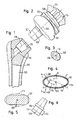
- FIG. 9 to 11 show a part of a shoulder joint prosthesis according to the invention, in a trained as a bearing head bearing body 11 with a shaft 13 is connected.
- the bearing body 11 without shaft 13 shows Fig. 12.
- the bearing body 11 is a cone with elliptical Cross-section formed clamping portion 15 connected in a correspondingly shaped counter-shape of the shaft 13 is einschlagbar to to produce a solid, releasable clamping seat of the cone 15 in the shaft 13.
- the orientation of the bearing body 11 relative to the cone 15 can during the operation according to the respective circumstances within certain limits are chosen arbitrarily.
- This coupling section is also formed such that the bearing body 11 in a during the operation selected relative position with respect to the cone 15 fixed can be.
- the bearing body 11 is provided with a support body 21.
- the support body 21 may be formed integrally with the bearing body 11 or as a separate, connectable to the bearing body 11 component be provided.
- the connection between the support body 21 and the Bearing body 11 may be designed so tight that bearing body 11 and Support body 21 form a solid, rigid configuration.
- the support body 21 adjustable on the bearing body 11 attach to a suitable for the particular application Configuration to be able to adjust.
- the support body 21 comprises a bowl-like portion 21b and a collar-like portion 21a, whose height - i. whose extension perpendicular to the bottom of the 19th of the bearing body 11 - in the of the collar-like portion 21 a away decreasing direction decreases.
- the support body 21 serves to the gap, which in with the Shank 13 connected bearing body 11 between the bottom 19 of the Lagergropers 11 and the shaft 13 is present, close and with to provide on its outside a support surface 23, at which bone fragments can support them, causing their growing together is favored.
- the support surface 23 closes of the support body 21 to the lateral surface of the shaft 13, which here in the Range of the transition from the shaft 13 into the support body 21 of a laterally seated on the shaft 13, basket-like support member 27 is formed will be discussed in more detail below.
- support body 21 according to the invention can in principle also without a provided on the shaft 13 support basket 27 are used.
- FIG. 11 is connected to the shaft 13 at Bearing body 11 between the support basket 27 of the shaft 13 and the shell-like portion 21 b of the support body 21 has a recess 31 present, to which for releasing the bearing body 11 of the shaft 13 a Tool can be set.
- the support body 21 here comprises only a cup-shaped Section whose outside forms the support surface 23.
- One additional collar-shaped section is not provided in this example, but also in shoulder joint prostheses with a ball cup trained bearing body 11 of the support body 21 is basically an additional Support section e.g. could have in collar shape. apart this also applies to this embodiment in conjunction with The above explained figures accordingly.
- Fig. 15 shows the basket or quiver-shaped shown in Figs. 9-11 and 13 Support member 27 in a view from above along the shaft axis 143 (see eg Fig. 9 and 13), d. H. the shaft axis 143 is perpendicular to the drawing plane in FIG. 15.
- the maximum outer diameter in the sagittal X and the maximum outer diameter in the transverse direction Y is such chosen for all intended within an implant set Sizes of the support member 27, the ratio X / Y in the range of 0.85 to 0.95 is.
- the openings 29 are designed and positioned in such a way that along a circumferential line 141 of the support member 27, the implanted in the State is in a plane which is perpendicular to the shaft axis 143 and in the proximal direction at a distance of 8 mm from the point of intersection 145 between the shaft axis 143 and the head or shell axis 147 runs, the proportion of interrupted due to the openings 29 Sections of the outer surface of the support member 27 in the range of 35% to 45%.
Abstract
Description
- Fig. 1
- schematisch einen in einem Oberarmknochen implantierten Schaft einer Schultergelenkprothese nach dem Stand der Technik,
- Fig. 2
- schematisch ein künstliches Schultergelenk mit einem als Lagerkopf ausgebildeten Lagerkörper nach dem Stand der Technik, der einen zu dem Schaft von Fig. 1 passenden konischen Körper aufweist,
- Fig. 3
- schematisch einen Querschnitt durch einen konischen Köper gemäß Fig. 2 mit einem elliptisch verlaufenden Umfang,
- Fig. 4
- schematisch einen Schnitt gemäß Fig. 3, an dem eine drehfeste Verkeilung zwischen konischem Körper und Gegenform dargestellt ist,
- Fig. 5
- schematisch einen Schnitt durch einen konischen Körper mit einem ursprünglichen Rechteckquerschnitt nach dem Stand der Technik, an dem nachträglich konische, im Schnitt elliptische Teilflächen passend zu einer Gegenform gemäß Fig. 4 hergestellt wurden,
- Fig. 6
- schematisch einen konischen Körper nach dem Stand der Technik, bei dem im mittleren Bereich der konischen Fläche eine Unterbrechung eingearbeitet ist,
- Fig. 7
- schematisch einen in einem Oberarmknochen implantierten Schaft nach dem Stand der Technik mit einer Gegenform für einen konischen Körper,
- Fig. 8
- schematisch einen zum Schaft von Fig. 7 passenden konischen Körper, der mit einem als Kugelschale ausgebildeten Lagerkörper ein künstliches Schultergelenk zu einem Kugelkopf nach dem Stand der Technik bildet, der über eine Plattform am Schulterknochen befestigt ist,
- Fig. 9
- einen Teil einer erfindungsgemäßen Schultergelenkprothese mit einem als Lagerkopf ausgebildeten Lagerkörper im mit einem Schaft verbundenen Zustand,
- Fig. 10
- eine andere Ansicht der erfindungsgemäßen Schultergelenkprothese von Fig. 9,
- Fig. 11
- eine weitere Ansicht der erfindungsgemäßen Schultergelenkprothese von Fig. 9,
- Fig. 12
- den mit einem Stützkörper und einem Spannkonus versehenen Lagerkörper der erfindungsgemäßen Schultergelenkprothese von Fig. 9,
- Fig. 13
- einen Teil einer anderen Ausführungsform einer erfindungsgemäßen Schultergelenkprothese mit einem als Lagerschale ausgebildeten Lagerkörper,
- Fig. 14
- den mit einem Stützkörper und einem Spannkonus versehenen Lagerkörper der erfindungsgemäßen Schultergelenkprothese von Fig. 13,
- Fig. 15
- eine Ansicht von oben eines Stützelementes einer Schultergelenkprothese gemäß einer Ausführungsform der Erfindung zur Erläuterung eines Außendurchmesserverhältnisses, und
- Fig. 16a und 16 b
- verschiedene Ansichten des Stützelementes von Fig. 15.
- 11
- Lagerkörper
- 13
- Schaft
- 15
- Kupplung, Spannabschnitt, Konus
- 19
- Unterseite des Lagerkörpers
- 21
- Stützkörper
- 21a
- kragenförmiger Abschnitt des Stützkörpers
- 21b
- schalenförmiger Abschnitt des Stützkörpers
- 23
- Stützfläche
- 27
- Stützelement, Stützkorb, Stützköcher
- 29
- Durchbruch
- 31
- Aussparung
- 101
- Lagerkopf
- 102
- Lagerschale
- 103
- Oberarmknochen
- 104
- Schulterknochen
- 105
- Schaft
- 106
- Plattform
- 107
- konischer Körper
- 108
- Umfang
- 109
- Längsachse
- 110
- Querschnitt
- 111
- Kugelkopf
- 112
- Kugelschale
- 114
- Zapfen
- 115
- Gegenform
- 116
- Bohrung
- 136
- Abstand
- 137
- Mindestabstand
- 138
- Unterbrechung
- 139
- radialer Abstand
- 141
- Umfangslinie
- 143
- Schaftachse
- 145
- Schnittpunkt
- 147
- Kopfachse, Schalenachse
Claims (21)
- Schultergelenkprothese mit zwei zusammenwirkenden Lagerkörpern (11), einem Schaft (13) und einer Kupplung (15) zum Verbinden des Schaftes (13) mit einem der Lagerkörper (11),
wobei sich an die Unterseite (19) des mit dem Schaft (13) verbindbaren Lagerkörpers (11) ein Stützkörper (21) anschließt, der im mit dem Schaft (13) verbundenen Zustand mit einer äußeren Stützfläche (23) eine zwischen dem Lagerkörper (11) und dem Schaft (13) vorhandene Lücke zumindest teilweise derart ausfüllt, dass das Zusammenwachsen von Knochenfragmenten begünstigt wird. - Schultergelenkprothese nach Anspruch 1,
dadurch gekennzeichnet, dass die Kupplung zur Verbindung mit dem Schaft (13) einen Spannabschnitt (15) umfasst, mit dem durch Einbringen in eine Kupplungsaufnahme des Schaftes (13) ein fester, insbesondere wieder lösbarer Spannsitz der Kupplung (15) im Schaft (13) herstellbar ist. - Schultergelenkprothese nach Anspruch 2,
dadurch gekennzeichnet, dass der Spannabschnitt (15) sich konusartig verjüngt und in eine entsprechend geformte, als Kupplungsaufnahme dienende Gegenform des Schaftes (13) einbringbar ist. - Schultergelenkprothese nach Anspruch 2 oder 3,
dadurch gekennzeichnet, dass der Spannabschnitt (15) im mit dem Schaft (13) verbundenen Zustand einen zu einer Längsachse drehfesten und durch seine Konizität verkeilten Formschluss mit der Gegenform bildet. - Schultergelenkprothese nach einem der Ansprüche 2 bis 4,
dadurch gekennzeichnet, dass der Spannabschnitt (15) einen von einer Kreisform abweichenden Querschnitt aufweist. - Schultergelenkprothese nach einem der Ansprüche 2 bis 5,
dadurch gekennzeichnet, dass der Spannabschnitt (15) einen elliptischen Querschnitt aufweist. - Schultergelenkprothese nach Anspruch 6,
dadurch gekennzeichnet, dass der elliptische Querschnitt des Spannabschnitts (15) und der Gegenform des Schaftes (13) derart in seiner Ebene ausgerichtet ist, dass die große Achse der Ellipse in einer Projektion gegen lateral als Senkrechte erscheint. - Schultergelenkprothese nach Anspruch 6 oder 7,
dadurch gekennzeichnet, dass der Schaft (13) in der Ebene des elliptischen Querschnitts den Umriss eines mit abgerundeten Ecken versehenen Rechtecks aufweist, dessen langen Seiten parallel zu der großen Achse der Ellipse verlaufen. - Schultergelenkprothese nach einem der vorhergehenden Ansprüche,
dadurch gekennzeichnet, dass die Stützfläche (23) des Stützkörpers (21) zumindest bereichsweise konvex ist. - Schultergelenkprothese nach einem der vorhergehenden Ansprüche,
dadurch gekennzeichnet, dass die Mantelfläche des Schaftes (13) und die Stützfläche (23) des Stützkörpers (21) zusammen eine zumindest im Wesentlichen geschlossene, sich an die Unterseite (19) des Lagerkörpers (11) anschließende Fläche bilden. - Schultergelenkprothese nach einem der vorhergehenden Ansprüche,
dadurch gekennzeichnet, dass die Stützfläche (23) des Stützkörpers (21) zumindest näherungsweise tangential an die Mantelfläche des Schaftes (13) anschließt. - Schultergelenkprothese nach einem der vorhergehenden Ansprüche,
dadurch gekennzeichnet, dass die Stützfläche (23) des Stützkörpers (21) strukturiert ist. - Schultergelenkprothese nach einem der vorhergehenden Ansprüche,
dadurch gekennzeichnet, dass die Stützfläche (23) des Stützkörpers (21) durchbrechungsfrei ausgebildet ist. - Schultergelenkprothese nach einem der vorhergehenden Ansprüche,
dadurch gekennzeichnet, dass der Stützkörper (21) auswechselbar mit dem Lagerkörper (11) verbunden ist. - Schultergelenkprothese nach einem der vorhergehenden Ansprüche,
dadurch gekennzeichnet, dass bei mit dem Schaft (13) verbundenem Lagerkörper (11) zwischen dem Schaft (13) und dem Stützkörper (21) wenigstens eine Aussparung (31) vorhanden ist, an die ein Werkzeug zum Lösen des Lagerkörpers (11) von dem Schaft (13) ansetzbar ist. - Schultergelenkprothese nach einem der vorhergehenden Ansprüche,
dadurch gekennzeichnet, dass der Schaft (13) mit einem insbesondere korb- oder köcherartigen Stützelement (27) versehen ist, das seitlich auf dem Schaft (13) aufsitzt und im Bereich des Übergangs vom Schaft (13) in den Stützkörper (21) mit seiner Außenseite die in die Stützfläche (23) des Stützkörpers (21) übergehende Mantelfläche des Schaftes (13) bildet. - Schultergelenkprothese nach Anspruch 16,
dadurch gekennzeichnet, dass das Stützelement (27) fest mit dem Schaft (13) verbunden, insbesondere mit dem Schaft verschweißt ist. - Schultergelenkprothese nach Anspruch 16,
dadurch gekennzeichnet, dass das Stützelement (27) einteilig mit dem Schaft (13) ausgebildet ist. - Schultergelenkprothese nach einem der Ansprüche 16 bis 18,
dadurch gekennzeichnet, dass das Stützelement (27) mit Durchbrüchen (29) versehen ist. - Schultergelenkprothese nach Anspruch 19,
dadurch gekennzeichnet, dass entlang einer Umfangslinie (141) des Stützelementes (27), die im implantierten Zustand in einer senkrecht zur Schaftachse (143) und in proximaler Richtung in einem Abstand von 8 mm von dem Schnittpunkt (145) zwischen der Schaftachse (143) und der Kopf- bzw. Schalenachse (147) verlaufenden Ebene liegt, der Anteil der aufgrund der Durchbrüche (29) unterbrochenen Abschnitte der Außenfläche des Stützelementes (27) im Bereich von 35 % bis 45 % liegt. - Schultergelenkprothese nach einem der Ansprüche 16 bis 20,
dadurch gekennzeichnet, dass bezogen auf die Orientierung des Stützelementes (27) im implantierten Zustand mit senkrecht zur Transversalebene verlaufender Schaftachse (143) das Verhältnis X/Y aus maximalem Außendurchmesser des Stützelementes (27) in sagittaler Richtung X und maximalem Außendurchmesser des Stützelementes (27) in transversaler Richtung Y im Bereich von 0,85 bis 0,95 liegt.
Priority Applications (2)
| Application Number | Priority Date | Filing Date | Title |
|---|---|---|---|
| EP03010285.9A EP1415621B1 (de) | 2002-08-21 | 2003-05-07 | Schultergelenkprothese |
| US10/646,064 US6899736B1 (en) | 2002-08-21 | 2003-08-21 | Shoulder joint prosthesis |
Applications Claiming Priority (3)
| Application Number | Priority Date | Filing Date | Title |
|---|---|---|---|
| EP02018730.8A EP1321114B1 (de) | 2001-11-21 | 2002-08-21 | Schultergelenkprothese |
| EP02018730 | 2002-08-21 | ||
| EP03010285.9A EP1415621B1 (de) | 2002-08-21 | 2003-05-07 | Schultergelenkprothese |
Publications (3)
| Publication Number | Publication Date |
|---|---|
| EP1415621A2 true EP1415621A2 (de) | 2004-05-06 |
| EP1415621A3 EP1415621A3 (de) | 2009-04-22 |
| EP1415621B1 EP1415621B1 (de) | 2016-09-14 |
Family
ID=32095024
Family Applications (1)
| Application Number | Title | Priority Date | Filing Date |
|---|---|---|---|
| EP03010285.9A Expired - Lifetime EP1415621B1 (de) | 2002-08-21 | 2003-05-07 | Schultergelenkprothese |
Country Status (2)
| Country | Link |
|---|---|
| US (1) | US6899736B1 (de) |
| EP (1) | EP1415621B1 (de) |
Cited By (18)
| Publication number | Priority date | Publication date | Assignee | Title |
|---|---|---|---|---|
| WO2007082925A2 (de) * | 2006-01-20 | 2007-07-26 | Zimmer Gmbh | Humeruskomponente |
| WO2010146545A1 (en) | 2009-06-18 | 2010-12-23 | Compagnie Financiere Et Medicale | Set of reconstruction of a fractured shoulder joint |
| US8075628B2 (en) | 2002-04-25 | 2011-12-13 | Zimmer, Inc. | Modular bone implant, tools, and method |
| US8152855B2 (en) | 2006-11-03 | 2012-04-10 | Howmedica Osteonics Corp. | Method and apparatus for hip femoral resurfacing tooling |
| US20130006369A1 (en) * | 2006-01-20 | 2013-01-03 | Wiley Roy C | Shoulder arthroplasty system |
| EP2604224A1 (de) * | 2011-10-31 | 2013-06-19 | Tornier Orthopedics Ireland Ltd. | Modulare reverse Schulterprothese |
| US8608805B2 (en) | 2005-09-16 | 2013-12-17 | Zimmer Gmbh | Insert and shell of a joint ball receptacle |
| FR2992548A1 (fr) * | 2012-06-29 | 2014-01-03 | Othesio Implants | Prothese pour l'articulation de l'epaule |
| US8690951B2 (en) | 2005-11-18 | 2014-04-08 | Zimmer, Gmbh | Base platform for an artificial joint |
| WO2014067961A1 (en) * | 2012-10-29 | 2014-05-08 | Tornier Orthopedics Ireland Ltd. | System for reverse shoulder implants |
| ITMI20122177A1 (it) * | 2012-12-19 | 2014-06-20 | Permedica S P A | Protesi di spalla di tipo migliorato |
| US10433967B2 (en) | 2014-12-10 | 2019-10-08 | Tornier | Convertible stem / fracture stem |
| US10898336B2 (en) | 2006-03-21 | 2021-01-26 | Tornier, Inc. | Femoral and humeral stem geometry and implantation method for orthopedic joint reconstruction |
| US10987226B2 (en) | 2016-04-19 | 2021-04-27 | Imascap Sas | Pre-operatively planned humeral implant and planning method |
| USD938590S1 (en) | 2019-10-01 | 2021-12-14 | Howmedica Osteonics Corp. | Humeral implant |
| US11197764B2 (en) | 2017-03-31 | 2021-12-14 | Howmedica Osteonics Corp. | Modular humeral head |
| US11369479B2 (en) | 2016-08-24 | 2022-06-28 | Howmedica Osteonics Corp. | Humeral head implant system |
| US11931264B2 (en) | 2018-10-02 | 2024-03-19 | Howmedica Osteonics Corp. | Modular humeral head |
Families Citing this family (27)
| Publication number | Priority date | Publication date | Assignee | Title |
|---|---|---|---|---|
| US7186269B2 (en) * | 2003-05-16 | 2007-03-06 | Jean-Maxwell Cyprien | Composite shoulder prosthesis |
| US7211113B2 (en) * | 2004-05-18 | 2007-05-01 | Lev Zelener | Hip prosthesis |
| US7241314B1 (en) * | 2004-09-16 | 2007-07-10 | Biomet Manufacturing Corp. | Reverse shoulder prosthesis |
| US20060074353A1 (en) * | 2004-09-27 | 2006-04-06 | Deffenbaugh Daren L | Glenoid instrumentation and associated method |
| US7922769B2 (en) * | 2004-09-27 | 2011-04-12 | Depuy Products, Inc. | Modular glenoid prosthesis and associated method |
| US20060069445A1 (en) * | 2004-09-27 | 2006-03-30 | Ondrla Jeffrey M | Extended articulation prosthesis adaptor and associated method |
| US7892287B2 (en) * | 2004-09-27 | 2011-02-22 | Depuy Products, Inc. | Glenoid augment and associated method |
| US7927335B2 (en) | 2004-09-27 | 2011-04-19 | Depuy Products, Inc. | Instrument for preparing an implant support surface and associated method |
| US8231684B2 (en) * | 2007-03-20 | 2012-07-31 | Tornier, Inc. | Humeral head augment device and method for use in a shoulder prosthesis |
| US8257363B2 (en) | 2007-10-12 | 2012-09-04 | Howmedica Osteonics Corp. | Expandable reverse shoulder trial |
| US8241365B2 (en) | 2008-12-23 | 2012-08-14 | Depuy Products, Inc. | Shoulder prosthesis with vault-filling structure having bone-sparing configuration |
| US8231683B2 (en) * | 2009-12-08 | 2012-07-31 | Depuy Products, Inc. | Shoulder prosthesis assembly having glenoid rim replacement structure |
| US8480750B2 (en) | 2010-11-24 | 2013-07-09 | DePuy Synthes Products, LLC | Modular glenoid prosthesis |
| US8465548B2 (en) | 2010-11-24 | 2013-06-18 | DePuy Synthes Products, LLC | Modular glenoid prosthesis |
| FR2972627B1 (fr) * | 2011-03-18 | 2013-03-22 | Fx Solutions | Tige humerale de prothese d'epaule, et ensemble forme par cette tige et par un element de reconstruction apte a etre assemble a cette tige |
| US9421106B2 (en) | 2011-12-07 | 2016-08-23 | Howmedica Osteonics Corp. | Reverse shoulder baseplate with alignment guide for glenosphere |
| US8945234B2 (en) | 2012-04-26 | 2015-02-03 | Optimus Orthopedic Designs LLC | Prosthesis having a metaphyseal element |
| US8906102B2 (en) | 2012-05-31 | 2014-12-09 | Howmedica Osteonics Corp. | Lateral entry insert for cup trial |
| US8663334B2 (en) * | 2012-05-31 | 2014-03-04 | Howmedica Osteonics Corp. | Lateral entry insert for cup trial |
| CA2907537C (en) * | 2012-08-01 | 2020-08-25 | Exactech, Inc. | Prosthetic devices to improve joint mechanics in arthroplasty |
| EP2873392B1 (de) * | 2013-11-14 | 2016-03-30 | Arthrex, Inc. | Schulterimplantat mit Schaft |
| US9597190B2 (en) | 2015-01-15 | 2017-03-21 | DePuy Synthes Products, Inc. | Modular reverse shoulder orthopaedic implant and method of implanting the same |
| US10390972B2 (en) | 2016-01-15 | 2019-08-27 | Howmedica Osteonics Corp. | Humeral trial adaptor |
| EP3419534B1 (de) | 2016-02-28 | 2022-11-23 | Integrated Shoulder Collaboration, Inc. | Implantatsystem für schulterarthroplastie |
| US11833055B2 (en) | 2016-02-28 | 2023-12-05 | Integrated Shoulder Collaboration, Inc. | Shoulder arthroplasty implant system |
| NL2020651B1 (nl) * | 2017-03-23 | 2018-12-21 | Cadskills Bvba | Botprothese en werkwijze voor plaatsing daarvan |
| CN111134904B (zh) * | 2018-11-06 | 2022-03-01 | 贵州澳特拉斯科技有限公司 | 仿生人工髋关节 |
Citations (9)
| Publication number | Priority date | Publication date | Assignee | Title |
|---|---|---|---|---|
| US3228393A (en) * | 1962-08-28 | 1966-01-11 | Arthur A Michele | Hip replacement prosthesis |
| EP0821924A1 (de) * | 1996-08-02 | 1998-02-04 | Tornier Sa | Durchlochte Humeruskopfprothese |
| EP0845250A2 (de) * | 1996-11-30 | 1998-06-03 | Depuy International Limited | Osteoprothesenteil |
| WO1999037254A1 (de) * | 1998-01-22 | 1999-07-29 | Sulzer Orthopedics, Ltd. | Humeruskopfprothese |
| WO2000018335A1 (en) * | 1998-09-25 | 2000-04-06 | Sulzer Orthopedics Inc. | Implantable humeral prosthesis having offset head and stem connection |
| EP1048274A2 (de) * | 1999-01-29 | 2000-11-02 | Depuy Orthopaedics, Inc. | Schultergelenkprothese mit Oberarmknochen-Bruchstütze |
| EP1059071A1 (de) * | 1999-06-09 | 2000-12-13 | Tornier Sa | Humerusprothese |
| EP1125565A2 (de) * | 2000-01-28 | 2001-08-22 | Cremascoli Ortho S.A | Schulterendoprothese für Brüche des oberen Endes des Oberarmknochens |
| US20020099445A1 (en) * | 2001-01-23 | 2002-07-25 | Maroney Brian J. | Method and apparatus for performing a shoulder replacement procedure in the treatment of cuff tear arthropathy |
Family Cites Families (12)
| Publication number | Priority date | Publication date | Assignee | Title |
|---|---|---|---|---|
| US4003095A (en) | 1976-04-29 | 1977-01-18 | Howmedica, Inc. | Trispherical prosthetic shoulder device |
| FR2685633B1 (fr) * | 1991-12-27 | 1998-02-27 | Tornier Sa | Prothese humerale modulaire. |
| FR2718954B1 (fr) | 1994-04-25 | 1996-08-02 | Euros Sa | Ensemble prothétique modulaire pour l'articulation de l'épaule. |
| FR2727857B1 (fr) | 1994-12-08 | 1997-01-24 | Cedior | Prothese totale d'epaule |
| US5569263A (en) | 1995-01-12 | 1996-10-29 | Orthopaedic Innovations, Inc. | Adjustable provisional articulating device |
| FR2743492B1 (fr) | 1996-01-15 | 1998-04-10 | Landanger Landos | Jeu de protheses de tete humerale |
| US5885295A (en) | 1996-08-07 | 1999-03-23 | Biomet, Inc. | Apparatus and method for positioning an orthopedic implant |
| GB9707371D0 (en) | 1997-04-11 | 1997-05-28 | Minnesota Mining & Mfg | A modular humeral prosthesis |
| ATE261707T1 (de) | 1998-01-16 | 2004-04-15 | Ct Pulse Orthopedics Ltd | Baukasten für schaftprothesen |
| FR2777772B1 (fr) | 1998-04-28 | 2000-11-03 | Depuy France | Prothese de reconstruction d'epaule |
| EP1321114B1 (de) | 2001-11-21 | 2018-03-07 | Zimmer GmbH | Schultergelenkprothese |
| EP1314407A1 (de) | 2001-11-21 | 2003-05-28 | Sulzer Orthopedics Ltd. | Schultergelenkprothese |
-
2003
- 2003-05-07 EP EP03010285.9A patent/EP1415621B1/de not_active Expired - Lifetime
- 2003-08-21 US US10/646,064 patent/US6899736B1/en not_active Expired - Lifetime
Patent Citations (9)
| Publication number | Priority date | Publication date | Assignee | Title |
|---|---|---|---|---|
| US3228393A (en) * | 1962-08-28 | 1966-01-11 | Arthur A Michele | Hip replacement prosthesis |
| EP0821924A1 (de) * | 1996-08-02 | 1998-02-04 | Tornier Sa | Durchlochte Humeruskopfprothese |
| EP0845250A2 (de) * | 1996-11-30 | 1998-06-03 | Depuy International Limited | Osteoprothesenteil |
| WO1999037254A1 (de) * | 1998-01-22 | 1999-07-29 | Sulzer Orthopedics, Ltd. | Humeruskopfprothese |
| WO2000018335A1 (en) * | 1998-09-25 | 2000-04-06 | Sulzer Orthopedics Inc. | Implantable humeral prosthesis having offset head and stem connection |
| EP1048274A2 (de) * | 1999-01-29 | 2000-11-02 | Depuy Orthopaedics, Inc. | Schultergelenkprothese mit Oberarmknochen-Bruchstütze |
| EP1059071A1 (de) * | 1999-06-09 | 2000-12-13 | Tornier Sa | Humerusprothese |
| EP1125565A2 (de) * | 2000-01-28 | 2001-08-22 | Cremascoli Ortho S.A | Schulterendoprothese für Brüche des oberen Endes des Oberarmknochens |
| US20020099445A1 (en) * | 2001-01-23 | 2002-07-25 | Maroney Brian J. | Method and apparatus for performing a shoulder replacement procedure in the treatment of cuff tear arthropathy |
Cited By (38)
| Publication number | Priority date | Publication date | Assignee | Title |
|---|---|---|---|---|
| US8075628B2 (en) | 2002-04-25 | 2011-12-13 | Zimmer, Inc. | Modular bone implant, tools, and method |
| US8608805B2 (en) | 2005-09-16 | 2013-12-17 | Zimmer Gmbh | Insert and shell of a joint ball receptacle |
| US8690951B2 (en) | 2005-11-18 | 2014-04-08 | Zimmer, Gmbh | Base platform for an artificial joint |
| US11298234B2 (en) | 2006-01-20 | 2022-04-12 | Zimmer, Inc. | Shoulder arthroplasty system |
| WO2007082925A3 (de) * | 2006-01-20 | 2007-10-04 | Zimmer Gmbh | Humeruskomponente |
| US10383735B2 (en) | 2006-01-20 | 2019-08-20 | Zimmer, Inc. | Shoulder arthroplasty system |
| WO2007082925A2 (de) * | 2006-01-20 | 2007-07-26 | Zimmer Gmbh | Humeruskomponente |
| US9770334B2 (en) | 2006-01-20 | 2017-09-26 | Zimmer, Inc. | Shoulder arthroplasty system |
| US20130006369A1 (en) * | 2006-01-20 | 2013-01-03 | Wiley Roy C | Shoulder arthroplasty system |
| US9283075B2 (en) * | 2006-01-20 | 2016-03-15 | Zimmer, Inc. | Shoulder arthroplasty system |
| US10898336B2 (en) | 2006-03-21 | 2021-01-26 | Tornier, Inc. | Femoral and humeral stem geometry and implantation method for orthopedic joint reconstruction |
| US8152855B2 (en) | 2006-11-03 | 2012-04-10 | Howmedica Osteonics Corp. | Method and apparatus for hip femoral resurfacing tooling |
| FR2946863A1 (fr) * | 2009-06-18 | 2010-12-24 | Cie Financiere Et Medicale | Ensemble de reconstruction d'une articulation de l'epaule fracturee. |
| WO2010146545A1 (en) | 2009-06-18 | 2010-12-23 | Compagnie Financiere Et Medicale | Set of reconstruction of a fractured shoulder joint |
| US11679006B2 (en) | 2011-10-31 | 2023-06-20 | Tornier Orthopedics Ireland, Ltd. | Systems for shoulder prostheses |
| EP2604224A1 (de) * | 2011-10-31 | 2013-06-19 | Tornier Orthopedics Ireland Ltd. | Modulare reverse Schulterprothese |
| US10548737B2 (en) | 2011-10-31 | 2020-02-04 | Tornier Orthopedics Ireland Ltd. | Reverse shoulder prostheses with anti-rotation features |
| US9498344B2 (en) | 2011-10-31 | 2016-11-22 | Tornier Orthopedics Ireland, Ltd. | Modular reverse shoulder prostheses |
| EP2773290B1 (de) * | 2011-10-31 | 2018-08-29 | Tornier Orthopedics Ireland Ltd. | Systeme für schulterprothesen |
| FR2992548A1 (fr) * | 2012-06-29 | 2014-01-03 | Othesio Implants | Prothese pour l'articulation de l'epaule |
| AU2016273961B2 (en) * | 2012-10-29 | 2018-06-14 | Stryker European Operations Limited | System for reverse shoulder implants |
| AU2013340867B2 (en) * | 2012-10-29 | 2016-09-22 | Stryker European Operations Limited | System for reverse shoulder implants |
| US10973645B2 (en) | 2012-10-29 | 2021-04-13 | Tornier Orthopedics Ireland, Ltd. | Systems for reverse shoulder implants |
| WO2014067961A1 (en) * | 2012-10-29 | 2014-05-08 | Tornier Orthopedics Ireland Ltd. | System for reverse shoulder implants |
| US10034759B2 (en) | 2012-10-29 | 2018-07-31 | Tornier Orthopedics Ireland Ltd. | Reverse shoulder implants |
| WO2014096912A1 (en) * | 2012-12-19 | 2014-06-26 | Permedica S.P.A. | Improved shoulder prosthesis |
| ITMI20122177A1 (it) * | 2012-12-19 | 2014-06-20 | Permedica S P A | Protesi di spalla di tipo migliorato |
| US11471291B2 (en) | 2014-12-10 | 2022-10-18 | Tornier Sas | Convertible stem/fracture stem |
| US10433967B2 (en) | 2014-12-10 | 2019-10-08 | Tornier | Convertible stem / fracture stem |
| US11173037B2 (en) | 2014-12-10 | 2021-11-16 | Tornier Sas | Convertible stem / fracture stem |
| US10987226B2 (en) | 2016-04-19 | 2021-04-27 | Imascap Sas | Pre-operatively planned humeral implant and planning method |
| US11607320B2 (en) | 2016-08-24 | 2023-03-21 | Howmedica Osteonics Corp. | Humeral head implant system |
| US11369479B2 (en) | 2016-08-24 | 2022-06-28 | Howmedica Osteonics Corp. | Humeral head implant system |
| US11197764B2 (en) | 2017-03-31 | 2021-12-14 | Howmedica Osteonics Corp. | Modular humeral head |
| US11925563B2 (en) | 2017-03-31 | 2024-03-12 | Howmedica Osteonics Corp. | Modular humeral head and related methods |
| US11931264B2 (en) | 2018-10-02 | 2024-03-19 | Howmedica Osteonics Corp. | Modular humeral head |
| USD983373S1 (en) | 2019-10-01 | 2023-04-11 | Howmedica Osteonics Corp. | Humeral implant |
| USD938590S1 (en) | 2019-10-01 | 2021-12-14 | Howmedica Osteonics Corp. | Humeral implant |
Also Published As
| Publication number | Publication date |
|---|---|
| US6899736B1 (en) | 2005-05-31 |
| EP1415621B1 (de) | 2016-09-14 |
| EP1415621A3 (de) | 2009-04-22 |
Similar Documents
| Publication | Publication Date | Title |
|---|---|---|
| EP1415621B1 (de) | Schultergelenkprothese | |
| EP0093230B1 (de) | Knochenimplantat, insbesondere femorale Hüftgelenkprothese | |
| EP1321114B1 (de) | Schultergelenkprothese | |
| EP0592897B1 (de) | Modularer Hüftprothesenschaft | |
| DE19841611B4 (de) | Implantierbare Prothese mit zumindest zwei gegeneinander verstellbaren Abschnitten sowie Verwendung verstellbarer Abschnitte | |
| EP0329019B1 (de) | Gelenkpfannenteil für eine Gelenkprothese | |
| EP1951161B1 (de) | Basisplattform für ein künstliches schultergelenk | |
| DE60304489T2 (de) | Spannmutter für eine osteosynthesevorrichtung | |
| DE3710233C2 (de) | ||
| EP0169978B1 (de) | Aus einem inneren Pfannenkörper und einer Aussenschale bestehende Endoprothese für eine Hüftgelenkspfanne | |
| EP0845251B1 (de) | Bausatz für eine modulare Femurkapfprothese, insbesondere eine Reoperationsprothese, und Femurkopfprothese aus einem derartigen Bausatz | |
| EP0654255B1 (de) | Innenschale für eine Hüftgelenkpfanne | |
| EP0447734B1 (de) | Knochenzementfreie Femurkopfprothese | |
| EP0135755A1 (de) | Schaft für eine Hüftgelenkprothese | |
| DE4330248A1 (de) | Gelenkprothese | |
| DE102008045291A1 (de) | Kniearthrodese-Implantat | |
| WO2007082925A2 (de) | Humeruskomponente | |
| WO2005079709A1 (de) | Prothese zum oberflächenersatz im bereich der kugel von kugelgelenken | |
| DE4442206A1 (de) | Gelenkprothese | |
| DE3336005C2 (de) | ||
| EP1314407A1 (de) | Schultergelenkprothese | |
| DE3903438C2 (de) | Modulare Hüftgelenk-Endoprothese | |
| DE19532898A1 (de) | Künstliche Hüftgelenkpfanne | |
| DE3737372A1 (de) | Implantierbare hueftgelenksprothese | |
| WO2003043543A1 (de) | Schenkelhalsendoprothese für ein künstliches hüftgelenk |
Legal Events
| Date | Code | Title | Description |
|---|---|---|---|
| PUAI | Public reference made under article 153(3) epc to a published international application that has entered the european phase |
Free format text: ORIGINAL CODE: 0009012 |
|
| AK | Designated contracting states |
Kind code of ref document: A2 Designated state(s): AT BE BG CH CY CZ DE DK EE ES FI FR GB GR HU IE IT LI LU MC NL PT RO SE SI SK TR |
|
| AX | Request for extension of the european patent |
Extension state: AL LT LV MK |
|
| RAP1 | Party data changed (applicant data changed or rights of an application transferred) |
Owner name: ZIMMER GMBH |
|
| PUAL | Search report despatched |
Free format text: ORIGINAL CODE: 0009013 |
|
| AK | Designated contracting states |
Kind code of ref document: A3 Designated state(s): AT BE BG CH CY CZ DE DK EE ES FI FR GB GR HU IE IT LI LU MC NL PT RO SE SI SK TR |
|
| AX | Request for extension of the european patent |
Extension state: AL LT LV MK |
|
| 17P | Request for examination filed |
Effective date: 20091002 |
|
| AKX | Designation fees paid |
Designated state(s): AT BE BG CH CY CZ DE DK EE ES FI FR GB GR HU IE IT LI LU MC NL PT RO SE SI SK TR |
|
| 17Q | First examination report despatched |
Effective date: 20140205 |
|
| GRAP | Despatch of communication of intention to grant a patent |
Free format text: ORIGINAL CODE: EPIDOSNIGR1 |
|
| INTG | Intention to grant announced |
Effective date: 20160511 |
|
| GRAS | Grant fee paid |
Free format text: ORIGINAL CODE: EPIDOSNIGR3 |
|
| GRAA | (expected) grant |
Free format text: ORIGINAL CODE: 0009210 |
|
| AK | Designated contracting states |
Kind code of ref document: B1 Designated state(s): AT BE BG CH CY CZ DE DK EE ES FI FR GB GR HU IE IT LI LU MC NL PT RO SE SI SK TR |
|
| REG | Reference to a national code |
Ref country code: GB Ref legal event code: FG4D Free format text: NOT ENGLISH |
|
| REG | Reference to a national code |
Ref country code: CH Ref legal event code: NV Representative=s name: DR. GRAF AND PARTNER AG INTELLECTUAL PROPERTY, CH Ref country code: CH Ref legal event code: EP |
|
| REG | Reference to a national code |
Ref country code: IE Ref legal event code: FG4D Free format text: LANGUAGE OF EP DOCUMENT: GERMAN |
|
| REG | Reference to a national code |
Ref country code: AT Ref legal event code: REF Ref document number: 828081 Country of ref document: AT Kind code of ref document: T Effective date: 20161015 |
|
| REG | Reference to a national code |
Ref country code: DE Ref legal event code: R096 Ref document number: 50315549 Country of ref document: DE |
|
| REG | Reference to a national code |
Ref country code: NL Ref legal event code: MP Effective date: 20160914 |
|
| PG25 | Lapsed in a contracting state [announced via postgrant information from national office to epo] |
Ref country code: FI Free format text: LAPSE BECAUSE OF FAILURE TO SUBMIT A TRANSLATION OF THE DESCRIPTION OR TO PAY THE FEE WITHIN THE PRESCRIBED TIME-LIMIT Effective date: 20160914 |
|
| PG25 | Lapsed in a contracting state [announced via postgrant information from national office to epo] |
Ref country code: SE Free format text: LAPSE BECAUSE OF FAILURE TO SUBMIT A TRANSLATION OF THE DESCRIPTION OR TO PAY THE FEE WITHIN THE PRESCRIBED TIME-LIMIT Effective date: 20160914 Ref country code: ES Free format text: LAPSE BECAUSE OF FAILURE TO SUBMIT A TRANSLATION OF THE DESCRIPTION OR TO PAY THE FEE WITHIN THE PRESCRIBED TIME-LIMIT Effective date: 20160914 Ref country code: NL Free format text: LAPSE BECAUSE OF FAILURE TO SUBMIT A TRANSLATION OF THE DESCRIPTION OR TO PAY THE FEE WITHIN THE PRESCRIBED TIME-LIMIT Effective date: 20160914 Ref country code: GR Free format text: LAPSE BECAUSE OF FAILURE TO SUBMIT A TRANSLATION OF THE DESCRIPTION OR TO PAY THE FEE WITHIN THE PRESCRIBED TIME-LIMIT Effective date: 20161215 |
|
| REG | Reference to a national code |
Ref country code: FR Ref legal event code: PLFP Year of fee payment: 15 |
|
| PG25 | Lapsed in a contracting state [announced via postgrant information from national office to epo] |
Ref country code: RO Free format text: LAPSE BECAUSE OF FAILURE TO SUBMIT A TRANSLATION OF THE DESCRIPTION OR TO PAY THE FEE WITHIN THE PRESCRIBED TIME-LIMIT Effective date: 20160914 Ref country code: EE Free format text: LAPSE BECAUSE OF FAILURE TO SUBMIT A TRANSLATION OF THE DESCRIPTION OR TO PAY THE FEE WITHIN THE PRESCRIBED TIME-LIMIT Effective date: 20160914 |
|
| PG25 | Lapsed in a contracting state [announced via postgrant information from national office to epo] |
Ref country code: BG Free format text: LAPSE BECAUSE OF FAILURE TO SUBMIT A TRANSLATION OF THE DESCRIPTION OR TO PAY THE FEE WITHIN THE PRESCRIBED TIME-LIMIT Effective date: 20161214 Ref country code: PT Free format text: LAPSE BECAUSE OF FAILURE TO SUBMIT A TRANSLATION OF THE DESCRIPTION OR TO PAY THE FEE WITHIN THE PRESCRIBED TIME-LIMIT Effective date: 20170116 Ref country code: CZ Free format text: LAPSE BECAUSE OF FAILURE TO SUBMIT A TRANSLATION OF THE DESCRIPTION OR TO PAY THE FEE WITHIN THE PRESCRIBED TIME-LIMIT Effective date: 20160914 Ref country code: SK Free format text: LAPSE BECAUSE OF FAILURE TO SUBMIT A TRANSLATION OF THE DESCRIPTION OR TO PAY THE FEE WITHIN THE PRESCRIBED TIME-LIMIT Effective date: 20160914 |
|
| REG | Reference to a national code |
Ref country code: DE Ref legal event code: R097 Ref document number: 50315549 Country of ref document: DE |
|
| PLBE | No opposition filed within time limit |
Free format text: ORIGINAL CODE: 0009261 |
|
| STAA | Information on the status of an ep patent application or granted ep patent |
Free format text: STATUS: NO OPPOSITION FILED WITHIN TIME LIMIT |
|
| PG25 | Lapsed in a contracting state [announced via postgrant information from national office to epo] |
Ref country code: DK Free format text: LAPSE BECAUSE OF FAILURE TO SUBMIT A TRANSLATION OF THE DESCRIPTION OR TO PAY THE FEE WITHIN THE PRESCRIBED TIME-LIMIT Effective date: 20160914 |
|
| 26N | No opposition filed |
Effective date: 20170615 |
|
| PG25 | Lapsed in a contracting state [announced via postgrant information from national office to epo] |
Ref country code: LU Free format text: LAPSE BECAUSE OF NON-PAYMENT OF DUE FEES Effective date: 20170531 |
|
| PG25 | Lapsed in a contracting state [announced via postgrant information from national office to epo] |
Ref country code: SI Free format text: LAPSE BECAUSE OF FAILURE TO SUBMIT A TRANSLATION OF THE DESCRIPTION OR TO PAY THE FEE WITHIN THE PRESCRIBED TIME-LIMIT Effective date: 20160914 |
|
| PG25 | Lapsed in a contracting state [announced via postgrant information from national office to epo] |
Ref country code: MC Free format text: LAPSE BECAUSE OF FAILURE TO SUBMIT A TRANSLATION OF THE DESCRIPTION OR TO PAY THE FEE WITHIN THE PRESCRIBED TIME-LIMIT Effective date: 20160914 |
|
| PG25 | Lapsed in a contracting state [announced via postgrant information from national office to epo] |
Ref country code: LU Free format text: LAPSE BECAUSE OF NON-PAYMENT OF DUE FEES Effective date: 20170507 |
|
| REG | Reference to a national code |
Ref country code: FR Ref legal event code: PLFP Year of fee payment: 16 |
|
| REG | Reference to a national code |
Ref country code: BE Ref legal event code: MM Effective date: 20170531 |
|
| REG | Reference to a national code |
Ref country code: AT Ref legal event code: MM01 Ref document number: 828081 Country of ref document: AT Kind code of ref document: T Effective date: 20170507 |
|
| PG25 | Lapsed in a contracting state [announced via postgrant information from national office to epo] |
Ref country code: AT Free format text: LAPSE BECAUSE OF NON-PAYMENT OF DUE FEES Effective date: 20170507 Ref country code: BE Free format text: LAPSE BECAUSE OF NON-PAYMENT OF DUE FEES Effective date: 20170531 |
|
| PG25 | Lapsed in a contracting state [announced via postgrant information from national office to epo] |
Ref country code: HU Free format text: LAPSE BECAUSE OF FAILURE TO SUBMIT A TRANSLATION OF THE DESCRIPTION OR TO PAY THE FEE WITHIN THE PRESCRIBED TIME-LIMIT; INVALID AB INITIO Effective date: 20030507 |
|
| PG25 | Lapsed in a contracting state [announced via postgrant information from national office to epo] |
Ref country code: CY Free format text: LAPSE BECAUSE OF NON-PAYMENT OF DUE FEES Effective date: 20160914 |
|
| PG25 | Lapsed in a contracting state [announced via postgrant information from national office to epo] |
Ref country code: TR Free format text: LAPSE BECAUSE OF FAILURE TO SUBMIT A TRANSLATION OF THE DESCRIPTION OR TO PAY THE FEE WITHIN THE PRESCRIBED TIME-LIMIT Effective date: 20160914 |
|
| PGFP | Annual fee paid to national office [announced via postgrant information from national office to epo] |
Ref country code: DE Payment date: 20200319 Year of fee payment: 18 |
|
| REG | Reference to a national code |
Ref country code: DE Ref legal event code: R119 Ref document number: 50315549 Country of ref document: DE |
|
| PG25 | Lapsed in a contracting state [announced via postgrant information from national office to epo] |
Ref country code: DE Free format text: LAPSE BECAUSE OF NON-PAYMENT OF DUE FEES Effective date: 20211201 |
|
| PGFP | Annual fee paid to national office [announced via postgrant information from national office to epo] |
Ref country code: IT Payment date: 20220316 Year of fee payment: 20 |
|
| PGFP | Annual fee paid to national office [announced via postgrant information from national office to epo] |
Ref country code: IE Payment date: 20220405 Year of fee payment: 20 Ref country code: GB Payment date: 20220406 Year of fee payment: 20 Ref country code: FR Payment date: 20220407 Year of fee payment: 20 |
|
| PGFP | Annual fee paid to national office [announced via postgrant information from national office to epo] |
Ref country code: CH Payment date: 20220408 Year of fee payment: 20 |
|
| REG | Reference to a national code |
Ref country code: CH Ref legal event code: PL |
|
| REG | Reference to a national code |
Ref country code: GB Ref legal event code: PE20 Expiry date: 20230506 |
|
| PG25 | Lapsed in a contracting state [announced via postgrant information from national office to epo] |
Ref country code: IE Free format text: LAPSE BECAUSE OF EXPIRATION OF PROTECTION Effective date: 20230507 |
|
| PG25 | Lapsed in a contracting state [announced via postgrant information from national office to epo] |
Ref country code: GB Free format text: LAPSE BECAUSE OF EXPIRATION OF PROTECTION Effective date: 20230506 |