EP1415089B1 - Windkraftanlage zur energiegewinnung - Google Patents
Windkraftanlage zur energiegewinnung Download PDFInfo
- Publication number
- EP1415089B1 EP1415089B1 EP02759863A EP02759863A EP1415089B1 EP 1415089 B1 EP1415089 B1 EP 1415089B1 EP 02759863 A EP02759863 A EP 02759863A EP 02759863 A EP02759863 A EP 02759863A EP 1415089 B1 EP1415089 B1 EP 1415089B1
- Authority
- EP
- European Patent Office
- Prior art keywords
- impeller
- wind power
- flow
- power unit
- unit according
- Prior art date
- Legal status (The legal status is an assumption and is not a legal conclusion. Google has not performed a legal analysis and makes no representation as to the accuracy of the status listed.)
- Expired - Lifetime
Links
Images




Classifications
-
- F—MECHANICAL ENGINEERING; LIGHTING; HEATING; WEAPONS; BLASTING
- F03—MACHINES OR ENGINES FOR LIQUIDS; WIND, SPRING, OR WEIGHT MOTORS; PRODUCING MECHANICAL POWER OR A REACTIVE PROPULSIVE THRUST, NOT OTHERWISE PROVIDED FOR
- F03D—WIND MOTORS
- F03D1/00—Wind motors with rotation axis substantially parallel to the air flow entering the rotor
- F03D1/04—Wind motors with rotation axis substantially parallel to the air flow entering the rotor having stationary wind-guiding means, e.g. with shrouds or channels
-
- F—MECHANICAL ENGINEERING; LIGHTING; HEATING; WEAPONS; BLASTING
- F03—MACHINES OR ENGINES FOR LIQUIDS; WIND, SPRING, OR WEIGHT MOTORS; PRODUCING MECHANICAL POWER OR A REACTIVE PROPULSIVE THRUST, NOT OTHERWISE PROVIDED FOR
- F03D—WIND MOTORS
- F03D9/00—Adaptations of wind motors for special use; Combinations of wind motors with apparatus driven thereby; Wind motors specially adapted for installation in particular locations
- F03D9/10—Combinations of wind motors with apparatus storing energy
- F03D9/12—Combinations of wind motors with apparatus storing energy storing kinetic energy, e.g. using flywheels
-
- F—MECHANICAL ENGINEERING; LIGHTING; HEATING; WEAPONS; BLASTING
- F03—MACHINES OR ENGINES FOR LIQUIDS; WIND, SPRING, OR WEIGHT MOTORS; PRODUCING MECHANICAL POWER OR A REACTIVE PROPULSIVE THRUST, NOT OTHERWISE PROVIDED FOR
- F03D—WIND MOTORS
- F03D9/00—Adaptations of wind motors for special use; Combinations of wind motors with apparatus driven thereby; Wind motors specially adapted for installation in particular locations
- F03D9/30—Wind motors specially adapted for installation in particular locations
- F03D9/32—Wind motors specially adapted for installation in particular locations on moving objects, e.g. vehicles
-
- F—MECHANICAL ENGINEERING; LIGHTING; HEATING; WEAPONS; BLASTING
- F05—INDEXING SCHEMES RELATING TO ENGINES OR PUMPS IN VARIOUS SUBCLASSES OF CLASSES F01-F04
- F05B—INDEXING SCHEME RELATING TO WIND, SPRING, WEIGHT, INERTIA OR LIKE MOTORS, TO MACHINES OR ENGINES FOR LIQUIDS COVERED BY SUBCLASSES F03B, F03D AND F03G
- F05B2240/00—Components
- F05B2240/10—Stators
- F05B2240/13—Stators to collect or cause flow towards or away from turbines
-
- F—MECHANICAL ENGINEERING; LIGHTING; HEATING; WEAPONS; BLASTING
- F05—INDEXING SCHEMES RELATING TO ENGINES OR PUMPS IN VARIOUS SUBCLASSES OF CLASSES F01-F04
- F05B—INDEXING SCHEME RELATING TO WIND, SPRING, WEIGHT, INERTIA OR LIKE MOTORS, TO MACHINES OR ENGINES FOR LIQUIDS COVERED BY SUBCLASSES F03B, F03D AND F03G
- F05B2240/00—Components
- F05B2240/10—Stators
- F05B2240/13—Stators to collect or cause flow towards or away from turbines
- F05B2240/131—Stators to collect or cause flow towards or away from turbines by means of vertical structures, i.e. chimneys
-
- F—MECHANICAL ENGINEERING; LIGHTING; HEATING; WEAPONS; BLASTING
- F05—INDEXING SCHEMES RELATING TO ENGINES OR PUMPS IN VARIOUS SUBCLASSES OF CLASSES F01-F04
- F05B—INDEXING SCHEME RELATING TO WIND, SPRING, WEIGHT, INERTIA OR LIKE MOTORS, TO MACHINES OR ENGINES FOR LIQUIDS COVERED BY SUBCLASSES F03B, F03D AND F03G
- F05B2240/00—Components
- F05B2240/20—Rotors
- F05B2240/33—Shrouds which are part of or which are rotating with the rotor
-
- Y—GENERAL TAGGING OF NEW TECHNOLOGICAL DEVELOPMENTS; GENERAL TAGGING OF CROSS-SECTIONAL TECHNOLOGIES SPANNING OVER SEVERAL SECTIONS OF THE IPC; TECHNICAL SUBJECTS COVERED BY FORMER USPC CROSS-REFERENCE ART COLLECTIONS [XRACs] AND DIGESTS
- Y02—TECHNOLOGIES OR APPLICATIONS FOR MITIGATION OR ADAPTATION AGAINST CLIMATE CHANGE
- Y02E—REDUCTION OF GREENHOUSE GAS [GHG] EMISSIONS, RELATED TO ENERGY GENERATION, TRANSMISSION OR DISTRIBUTION
- Y02E10/00—Energy generation through renewable energy sources
- Y02E10/70—Wind energy
- Y02E10/72—Wind turbines with rotation axis in wind direction
-
- Y—GENERAL TAGGING OF NEW TECHNOLOGICAL DEVELOPMENTS; GENERAL TAGGING OF CROSS-SECTIONAL TECHNOLOGIES SPANNING OVER SEVERAL SECTIONS OF THE IPC; TECHNICAL SUBJECTS COVERED BY FORMER USPC CROSS-REFERENCE ART COLLECTIONS [XRACs] AND DIGESTS
- Y02—TECHNOLOGIES OR APPLICATIONS FOR MITIGATION OR ADAPTATION AGAINST CLIMATE CHANGE
- Y02E—REDUCTION OF GREENHOUSE GAS [GHG] EMISSIONS, RELATED TO ENERGY GENERATION, TRANSMISSION OR DISTRIBUTION
- Y02E10/00—Energy generation through renewable energy sources
- Y02E10/70—Wind energy
- Y02E10/728—Onshore wind turbines
-
- Y—GENERAL TAGGING OF NEW TECHNOLOGICAL DEVELOPMENTS; GENERAL TAGGING OF CROSS-SECTIONAL TECHNOLOGIES SPANNING OVER SEVERAL SECTIONS OF THE IPC; TECHNICAL SUBJECTS COVERED BY FORMER USPC CROSS-REFERENCE ART COLLECTIONS [XRACs] AND DIGESTS
- Y02—TECHNOLOGIES OR APPLICATIONS FOR MITIGATION OR ADAPTATION AGAINST CLIMATE CHANGE
- Y02E—REDUCTION OF GREENHOUSE GAS [GHG] EMISSIONS, RELATED TO ENERGY GENERATION, TRANSMISSION OR DISTRIBUTION
- Y02E60/00—Enabling technologies; Technologies with a potential or indirect contribution to GHG emissions mitigation
- Y02E60/16—Mechanical energy storage, e.g. flywheels or pressurised fluids
-
- Y—GENERAL TAGGING OF NEW TECHNOLOGICAL DEVELOPMENTS; GENERAL TAGGING OF CROSS-SECTIONAL TECHNOLOGIES SPANNING OVER SEVERAL SECTIONS OF THE IPC; TECHNICAL SUBJECTS COVERED BY FORMER USPC CROSS-REFERENCE ART COLLECTIONS [XRACs] AND DIGESTS
- Y02—TECHNOLOGIES OR APPLICATIONS FOR MITIGATION OR ADAPTATION AGAINST CLIMATE CHANGE
- Y02E—REDUCTION OF GREENHOUSE GAS [GHG] EMISSIONS, RELATED TO ENERGY GENERATION, TRANSMISSION OR DISTRIBUTION
- Y02E70/00—Other energy conversion or management systems reducing GHG emissions
- Y02E70/30—Systems combining energy storage with energy generation of non-fossil origin
Definitions
- the invention relates to a wind turbine for energy production with an axially flowed through, rotatably mounted on a shaft, provided with blades impeller and with an air flow through the impeller accelerating guide.
- the invention is therefore an object of the invention to overcome these deficiencies, and to provide a wind turbine of the type described, the uses the available wind energy in a compact size as advantageous as possible.
- the invention solves this problem in that the guide consists of several flow channels tapering in the flow direction, which are arranged distributed on the impeller around a shaft, that the blades are each associated with a flow channel and that the impeller has an outer jacket enclosing it.
- a significant proportion of the increase in efficiency of the wind turbine according to the invention is that almost the entire projecting base of the impeller uses the air flow, for which it has the plurality of annularly distributed around the shaft flow channels for the air flow, which individual flow channels are assigned per blades. Each flow channel thus has its own guide, with which it supplies the air flow to the respective blades. Due to the particular embodiment of the individual flow channels and the provision of the outer shell surrounding the impeller, the dynamic pressure upstream of the impeller is additionally increased, as a result of which the air flowing through the impeller is additionally accelerated.
- the blades may be provided in the flow channels as far as the flow channel end or beyond the flow channel end. If a structurally simple construction is to be created, it is advisable to arrange the blades to the respective flow channel.
- the blades are adjustable, so that the angle of attack the blades can be adapted to the prevailing air flow.
- guide walls are arranged in the flow channels in front of the blades, which convey the air flow to the blades.
- These baffles may be, for example, inclined guide rails, which redirect the flow of air to the flow channel center.
- the impeller may be a coaxial with the impeller mounted flywheel, which is releasably connected by means of a coupling with the impeller.
- the flywheel is released during the starting process, for example, from the impeller to reduce the moment of inertia of the impeller and to accelerate the starting process, especially at low wind speeds. If the impeller then reaches its desired operating speed, the flywheel can be slowly coupled to the impeller and thus ultimately serve as an energy storage to compensate for speed fluctuations.
- a particularly high moment of inertia and thus compensation for speed fluctuations and simple design conditions arise when the flywheel is arranged in the outer jacket of the impeller.
- This carrier vehicle may be, for example, an excavator vehicle, on the excavator arm of the wind turbine is mounted.
- the wind tracking is controlled in this case via the turntable of the tracked vehicle.
- the tracked vehicle can approach even difficult-to-access locations in the terrain easily and without additional aids.
- the impeller sitting on a supplementary shaft, nachordnen axially flowed auxiliary wheel may for example be provided with a conventional rotor blade system, which rotor blades are preferably designed to adapt to the particular circumstances adjustable.
- the wind turbine according to the invention is od with either aligned against the wind horizontal axis of rotation on a mast.
- the impeller is mounted with a vertical axis in a tower having a coaxial with the impeller adjustable tower head with a horizontal wind flow against the impeller deflecting elbow whereby the pressure gradient between the upper and lower sides of the tower, that is to say between the inlet and the outlet, can be used to generate energy.
- the wind speed is to be additionally increased by the impeller, it is advantageous if the flow connection of the pipe elbow to the impeller narrows in the flow direction.
- the impeller and / or the auxiliary wheel is assigned a braking device with which either one or the other wheel can be braked to a stop.
- a wind power plant 1 for generating energy consists essentially of an axially flowed through, mounted on a shaft 2 and provided with blades 3 impeller 4 and from the air flow through the impeller 4 accelerating guide 5.
- the guide 5 is composed of several flow channels tapering in the flow direction 6 together. These flow channels 6 are distributed with their guide devices 5 on the impeller 4 in a circle around the shaft 2 in order to be able to use the air flow over the entire flowed cross-section of the impeller 4.
- the rotor blades 3 are each arranged downstream of a flow channel 6 and the impeller 4 has an outer jacket 7 surrounding it. This outer shell has an annular nozzle shape, whereby the dynamic pressure before the impeller 4 is to be increased.
- the annular guide devices 5 increase the dynamic pressure.
- the impeller 4 is a sitting on a supplementary shaft not shown, as well as the impeller axially flowed auxiliary impeller 18, downstream for better utilization of wind energy (Fig. 3).
- the auxiliary rotor 18 also drives a
- the flow channels 6 expand following their rejuvenation again.
- the blades may have a wing profile.
- the rotor blades 3 also form nozzle-shaped flow channels between them, the flow channels tapering between the points m and n (FIG. 8) and then widening again.
- the blades 3 are designed to adjust to the prevailing wind speed adjustable.
- 3 baffles 8 may be arranged in individual flow channels 6 in front of the blades. These baffles 8 are intended to force the flow of air within the flow channels 6 against the blades directed flow.
- the wind turbine according to the invention can be arranged according to FIGS. 4 and 5 on a mobile carrier vehicle 9 to ensure the mobile use of the wind turbine 1.
- the impeller 4 is mounted on the shaft 2, which is rotatably mounted in a housing 11 and connected via a gear 10 and a clutch 12 to a generator 13, whereby the wind energy is converted into electrical energy.
- the wind turbine 1 is mounted on a boom 14 of the carrier vehicle 9.
- the Windnach arrangement the wind turbine 1 via a turntable 15 of the carrier vehicle, for example by means of an engaging in the turntable 15 electric motor.
- the wind turbine 1 according to the invention is mounted on a lattice mast 16.
- the impeller 3 has coaxial with the shaft 2, a central displacement body 17 which simultaneously forms a hub for receiving the impeller 4 and the air flow from the inner wheel region, in which the useful effect would be very small due to the small distance to the axis of rotation, the more outer flow channels zunot, whereby the back pressure in front of the impeller 4 is additionally increased.
- the impeller 4 is mounted with a vertical axis in a tower 20 having a coaxial with the impeller 4 adjustable tower head 21 with a horizontal wind flow against the impeller 4 deflecting pipe elbow 22.
- Flow connection 23 of the pipe elbow 22 to the impeller 4 narrows in the flow direction of the flowing through the pipe elbow 22 on the impeller 4 air.
- the air flow is the impeller 4 supplied via the mounted on a turntable 24 tower head 21.
- Wind tracking takes place via a ring gear motor 25 acting on the turntable 24, which is controlled by a wind direction sensor 26 as a function of the respective prevailing wind direction.
- the tower head 21 is supported by a bearing 27 on the tower.
- the impeller 4 is drivingly connected on the one hand with a flywheel 28 arranged near the tower wall and on the other hand with a generator 29.
- the generator 29 is driven by means of a flat belt 30 which engages the flywheel 28.
- the air flowing into the tower 20 leaves the tower 20 near the turret via pipes 31.
- controllable valves 32 are provided for controlling the air flow flowing through the wind turbine 1.
- the pipes 31 can be laid down the ground from the turbine floor (FIG. 13) to any prevailing pressure differences between air inlet and outlet also to use for energy.
Landscapes
- Engineering & Computer Science (AREA)
- Life Sciences & Earth Sciences (AREA)
- Sustainable Development (AREA)
- Sustainable Energy (AREA)
- Chemical & Material Sciences (AREA)
- Combustion & Propulsion (AREA)
- Mechanical Engineering (AREA)
- General Engineering & Computer Science (AREA)
- Power Engineering (AREA)
- Wind Motors (AREA)
Description
- Die Erfindung bezieht sich auf eine Windkraftanlage zur Energiegewinnung mit einem axial durchströmten, auf einer Welle drehbar gelagerten, mit Laufschaufeln versehenen Laufrad und mit einer die Luftströmung durch das Laufrad beschleunigenden Leiteinrichtung.
- Übliche Windkraftanlagen besitzen meist propellerartige Laufräder die zur Erzeugung von Energie in bzw. entgegen der Windrichtung ausgerichtet werden. Die bekannten Laufräder besitzen allerdings den Nachteil, daß ihre Wirtschaftlichkeit insbesondere bei kleinen Windgeschwindigkeiten und bei kleineren Durchmessern äußerst gering ist siehe EP-A-0 045 264. Um dies zu verbessern ist es bekannt (DE 33 23 200 A), die Luft dem Laufrad über eine trichterförmige Leiteinrichtung zuzuführen. Die Leiteinrichtung besitzt eine sich bis zum Turbinenrad verjüngende düsenartige Form, die den Luftstrom durch das Laufrad beschleunigen soll. Diese bekannte Windkraftanlage hat aber eine erhebliche Baugröße, insbesondere Baulänge, weshalb sie sich kaum in großem Umfang kommerziell nutzen läßt, wie insbesondere für den Privatbereich.
- Der Erfindung liegt somit die Aufgabe zugrunde, diese Mängel zu beseitigen, und eine Windkraftanlage der eingangs geschilderten Art bereitzustellen, die die zur Verfügung stehende Windenergie bei einer kompakten Baugröße möglichst vorteilhaft nutzt.
- Die Erfindung löst diese Aufgabe dadurch, daß die Leiteinrichtung aus mehreren sich in Strömungsrichtung verjüngenden Strömungskanälen besteht, die auf dem Laufradkranz um eine Welle verteilt angeordnet sind, daß die Laufschaufeln jeweils einem Strömungskanal zugeordnet sind und daß das Laufrad einen es umschließenden Außenmantel aufweist.
- Ein wesentlicher Anteil an der Wirkungsgradsteigerung der erfindungsgemäßen Windkraftanlage liegt darin, daß nahezu die gesamte projizierende Grundfläche des Laufrades die Luftströmung ausnutzt, wozu es die Vielzahl an kranzförmig um die Welle verteilt angeordneten Strömungskanälen für die Luftströmung aufweist, welchen einzelnen Strömungskanälen je Laufschaufeln zugeordnet sind. Jeder Strömungskanal besitzt somit seine eigene Leiteinrichtung, mit der er die Luftströmung den jeweiligen Schaufeln zuführt. Durch die besondere Ausgestaltungsform der einzelnen Strömungskanäle und das Vorsehen des das Laufrad umschließenden Außenmantels wird der Staudruck vor dem Laufrad zusätzlich erhöht, wodurch die durch das Laufrad strömende Luft zusätzlich beschleunigt wird. Die Laufschaufeln können beispielsweise in den Strömungskanälen bis zum Strömungskanalende oder über das Strömungskanalende hinaus angeordnet vorgesehen sein. Soll eine konstruktiv einfache Konstruktion geschaffen werden, empfiehlt es sich die Laufschaufeln dem jeweiligen Strömungskanal nachzuordnen.
- Besonders vorteilhafte Verhältnisse ergeben sich für die Windkraftanlage, wenn sich die Strömungskanäle im Anschluß an ihre Verjüngung wieder erweitern, wobei die einzelnen Strömungsquerschnitte dann düsenförmig ausgebildet sind und sich im Bereich der Laufschaufeln eine maximale Strömungsgeschwindigkeit einstellt. Um die erfindungsgemäße Windkraftanlage über einen großen Geschwindigkeitsbereich einer Luftströmung bestmöglich einsetzen zu können, sind die Laufschaufeln verstellbar ausgebildet, so daß der Anstellwinkel der Laufschaufeln an die jeweils vorherrschende Luftströmung angepaßt werden kann.
- Nach einer vorteilhaften Weiterbildung der Erfindung sind in den Strömungskanälen vor den Laufschaufeln Leitwände angeordnet, welche die Luftströmung den Laufschaufeln zuleiten. Diese Leitwände können beispielsweise schräg gestellte Leitschienen sein, welche die Luftströmung zur Strömungskanalmitte hin umleiten.
- Um beispielsweise bei böigen Windverhältnissen eine möglichst konstante Drehzahl des Laufrades gewährleisten zu können, kann dem Laufrad eine koaxial zum Laufrad gelagerte Schwungscheibe zugehören, die mittels einer Kupplung lösbar mit dem Laufrad verbunden ist. So wird die Schwungscheibe während des Anfahrvorganges beispielsweise vom Laufrad gelöst um das Trägheitsmoment des Laufrades zu mindern und um den Anlaufvorgang insbesondere bei geringen Windstärken zu beschleunigen. Hat das Laufrad dann seine gewünschte Betriebsdrehzahl erreicht, kann das Schwungrad langsam an das Laufrad gekuppelt werden und somit schließlich als Energiespeicher zum Ausgleich von Drehzahlschwankungen dienen. Ein besonders hohes Trägheitsmoment und somit Ausgleichsvermögen für Drehzahlschwankungen und einfache Konstruktionsverhältnisse ergeben sich, wenn die Schwungscheibe im Außenmantel des Laufrades angeordnet ist.
- Ist eine mobile Nutzung der erfindungsgemäßen Windkraftanlage gewünscht, wird sie auf ein Trägerfahrzeug aufgebaut. Dieses Trägerfahrzeug kann beispielsweise ein Baggerfahrzeug sein, auf dessen Baggerarm die Windkraftanlage montiert ist. Die Windnachführung wird in diesem Fall über den Drehkranz des Kettenfahrzeuges geregelt. Das Kettenfahrzeug kann im Gelände selbst schwer zugängliche Standorte leicht und ohne zusätzliche Hilfsmittel anfahren.
- Soll der Wirkungsgrad der erfindungsgemäßen Windkraftanlage noch weiter gesteigert bzw. die zur Verfügung stehende Windenergie noch besser genutzt werden, wird vorgeschlagen, dem Laufrad ein auf einer Zusatzwelle sitzendes, axial durchströmtes Hilfslaufrad nachzuordnen. Das Hilfslaufrad kann beispielsweise mit einem herkömmlichen Rotorblattsystem versehen sein, welche Rotorblätter zur Anpassung an die jeweiligen Gegebenheiten vorzugsweise verstellbar ausgebildet sind.
- Die erfindungsgemäße Windkraftanlage ist entweder mit gegen den Wind ausgerichteten horizontaler Drehachse auf einem Masten od. dgl. angeordnet, oder das Laufrad ist mit vertikaler Achse in einem Turm gelagert, der einen koaxial zum Laufrad verstellbaren Turmkopf mit einem die horizontale Windströmung gegen das Laufrad umlenkenden Rohrknie aufweist, womit auch das Druckgefälle zwischen Turmober- und -unterseite, also zwischen Einlaß und Auslaß zur Energiegewinnung genutzt werden kann. Soll die Windgeschwindigkeit durch das Laufrad zusätzlich erhöht werden, ist es vorteilhaft, wenn sich der Strömungsanschluß des Rohrknies an das Laufrad in Strömungsrichtung verengt.
- Um bedarfsweise entweder das Laufrad oder das Hilfslaufrad im Betrieb als Leiteinrichtung für das jeweils andere Rad einsetzen zu können, ist dem Laufrad und/oder dem Hilfslaufrad eine Bremseinrichtung zugeordnet, mit der entweder das eine oder das andere Rad bis zum Stillstand abgebremst werden kann.
- Die Erfindung ist in der Zeichnung anhand eines Ausführungsbeispieles schematisch dargestellt. Es zeigen:
- Fig. 1
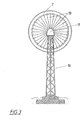
- eine erfindungsgemäße Windkraftanlage in Vorderansicht,
- Fig. 2
- die Windkraftanlage aus Fig. 2 in teilgeschnittener Seitenansicht,
- Fig. 3
- die Windkraftanlage aus den Fig. 1 und 2 in Hinteransicht mit dem Laufrad nachgeordnetem Hilfslaufrad,
- Fig. 4 und 5
- eine Ausgestaltungsvariante der Windkraftanlage aus den Fig. 2 und 3 in Vorder- und Seitenansicht,
- Fig. 6
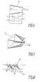
- ein Geschwindigkeits- und Druckverteilungsschema für einen Strömungskanal,
- Fig. 7
- in einem Strömungskanal angeordnete Leitwände,
- Fig. 8
- ein Ausführungsbeispiel für Laufschaufeln,
- Fig. 9 und 10
- eine in einem Turm angeordnete erfindungsgemäße Windkraftanlage in geschnittener Vorderansicht und Seitenansicht,
- Fig. 11 und 12
- die Windkraftanlage aus der Fig. 9 und 10 in teilgeschnittener Draufsicht und
- Fig. 13
- eine Verbauungsvariante der Windkraftanlage aus den Fig. 9 bis 12 in teilgeschnittener Seitenansicht.
- Eine Windkraftanlage 1 zur Energiegewinnung besteht im wesentlichen aus einem axial durchströmten, auf einer Welle 2 befestigten und mit Laufschaufeln 3 versehenen Laufrad 4 und aus einer die Luftströmung durch das Laufrad 4 beschleunigenden Leiteinrichtung 5. Die Leiteinrichtung 5 setzt sich aus mehreren sich in Strömungsrichtung verjüngenden Strömungskanälen 6 zusammen. Diese Strömungskanäle 6 sind mit ihren Leiteinrichtungen 5 auf dem Laufrad 4 kranzförmig um die Welle 2 verteilt angeordnet, um die Luftströmung über den gesamten angeströmten Querschnitt des Laufrades 4 nutzen zu können. Die Laufschaufeln 3 sind jeweils einem Strömungskanal 6 nachgeordnet und das Laufrad 4 weist einen es umschließenden Außenmantel 7 auf. Dieser Außenmantel besitzt eine Ringdüsenform, wodurch der Staudruck vor dem Laufrad 4 erhöht werden soll. Ebenso erhöhen die kranzförmigen Leiteinrichtungen 5 den Staudruck. Dem Laufrad 4 ist ein auf einer nicht näher dargestellten Zusatzwelle sitzendes, ebenso wie das Laufrad axial durchströmtes Hilfslaufrad 18, zur besseren Ausnutzung der Windenergie nachgeordnet (Fig. 3). Das Hilfslaufrad 18 treibt ebenfalls einen Generator an.
- Die Strömungskanäle 6 erweitern sich im Anschluß an ihre Verjüngung wieder. Zur Steigerung des Nutzungsgrades der Windkraftanlage 1 können die Laufschaufeln ein Tragflächenprofil besitzen. Vorteilhafterweise bilden die Laufschaufeln 3 zwischen sich ebenfalls düsenförmige Strömungskanäle aus, wobei sich die Strömungskanäle zwischen den Punkten m und n (Fig. 8) verjüngen und anschließend wieder erweitern. Die Laufschaufeln 3 sind zur Anpassung an die vorherrschende Windgeschwindigkeit verstellbar ausgebildet. Ebenso können in einzelnen Strömungskanälen 6 vor den Laufschaufeln 3 Leitwände 8 angeordnet sein. Diese Leitwände 8 sollen dem Luftstrom innerhalb der Strömungskanäle 6 eine gegen die Laufschaufeln gerichtete Strömung aufzwingen.
- Die erfindungsgemäße Windkraftanlage kann gemäß den Fig. 4 und 5 auf einem mobilen Trägerfahrzeug 9 angeordnet sein, um die mobile Nutzung der Windkraftanlage 1 sicherzustellen. Das Laufrad 4 ist auf der Welle 2 befestigt, die in einem Gehäuse 11 drehbar gelagert und über ein Getriebe 10 und eine Kupplung 12 an einen Generator 13 angeschlossen ist, wodurch die Windenergie in elektrische Energie umsetzt wird. Die Windkraftanlage 1 ist auf einem Ausleger 14 des Trägerfahrzeuges 9 montiert. Die Windnachführung der Windkraftanlage 1 erfolgt über einen Drehkranz 15 des Trägerfahrzeuges, beispielsweise mittels eines in den Drehkranz 15 eingreifenden Elektromotors. Nach den Fig. 2 und 3 ist die erfindungsgemäße Windkraftanlage 1 auf einem Gittermast 16 montiert. Das Laufrad 3 besitzt koaxial zur Welle 2 einen mittleren Verdrängungskörper 17, der gleichzeitig eine Nabe zur Aufnahme des Laufrades 4 ausbildet und die Luftströmung aus dem inneren Radbereich, in dem die Nutzwirkung aufgrund des geringen Abstandes zur Drehachse sehr klein wäre, den weiter außen liegenden Strömungskanälen zuleitet, wodurch der Staudruck vor dem Laufrad 4 zusätzlich erhöht wird.
- Nach der Ausgestaltungsvariante einer erfindungsgemäßen Windkraftanlage 1, ist das Laufrad 4 mit vertikaler Achse in einem Turm 20 gelagert, der einen koaxial zum Laufrad 4 verstellbaren Turmkopf 21 mit einem die horizontale Windströmung gegen das Laufrad 4 umlenkenden Rohrknie 22 aufweist. Der Strömungsanschluß 23 des Rohrknies 22 an das Laufrad 4 verengt sich in Strömungsrichtung der durch das Rohrknie 22 auf das Laufrad 4 zuströmenden Luft. Der Luftstrom wird dem Laufrad 4 über den auf einem Drehkranz 24 gelagerten Turmkopf 21 zugeführt. Die Windnachführung erfolgt über einen auf den Drehkranz 24 wirkenden Drehkranzmotor 25, der in Abhängigkeit der jeweils vorherrschenden Windrichtung von einem Windrichtungssensor 26 angesteuert wird. Der Turmkopf 21 stützt sich über ein Lager 27 am Turm ab.
- Das Laufrad 4 ist einerseits mit einer in Turmbodennähe angeordneten Schwungscheibe 28 und anderseits mit einem Generator 29 antriebsverbunden. Gemäß dem Ausführungsbeispiel wird der Generator 29 mittels eines Flachriemens 30 angetrieben der an der Schwungscheibe 28 angreift. Die in den Turm 20 einströmende Luft verläßt den Turm 20 in Turmbodennähe über Rohre 31. Am Ende der Rohre 31 sind regelbare Ventile 32 zur Regelung des die Windkraftanlage 1 durchströmenden Luftstromes vorgesehen. Im Falle, daß das Gelände auf dem die erfindungsgemäße Windkraftanlage versetzt ist, auf wenigstens einer Seite des Turmes 20 abfällt, können die Rohre 31 vom Turbinenboden das Gelände hinab verlegt werden (Fig. 13), um eventuell vorherrschende Druckdifferenzen zwischen Lufteintritt und -austritt ebenfalls zur Energiegewinnung nutzen zu können.
Claims (13)
- Windkraftanlage zur Energiegewinnung mit einem axial durchströmten, auf einer Welle drehbar gelagerten, mit Laufschaufeln versehenen Laufrad und mit einer die Luftströmung durch das Laufrad beschleunigenden Leiteinrichtung, dadurch gekennzeichnet, daß die Leiteinrichtung (5) aus mehreren sich in Strömungsrichtung verjüngenden Strömungskanälen (6) besteht, die auf dem Laufrad (4) kranzförmig um die Welle (2) verteilt angeordnet sind, daß die Laufschaufeln (3) jeweils einem Strömungskanal (6) zugeordnet sind und daß das Laufrad (4) einen es umschließenden Außenmantel (7) aufweist.
- Windkraftanlage nach Anspruch 1, dadurch gekennzeichnet, daß die Laufschaufeln (3) jeweils einem Strömungskanal (6) nachgeordnet sind.
- Windkraftanlage nach Anspruch 1 oder 2, dadurch gekennzeichnet, daß sich die Strömungskanäle (6) im Anschluß an ihre Verjüngung wieder erweitern.
- Windkraftanlage nach einem der Ansprüche 1 bis 3, dadurch gekennzeichnet, daß die Laufschaufeln (3) verstellbar ausgebildet sind.
- Windkraftanlage nach einem der Ansprüche 1 bis 4, dadurch gekennzeichnet, daß in den Strömungskanälen (6) vor den Laufschaufeln (3) Leitwände (8) angeordnet sind.
- Windkraftanlage nach einem der Ansprüche 1 bis 5, dadurch gekennzeichnet, daß dem Laufrad (4) eine koaxial zum Laufrad (4) gelagerte Schwungscheibe (28) zugehört, die mittels einer Kupplung lösbar mit dem Laufrad (4) verbunden ist.
- Windkraftanlage nach Anspruch 6, dadurch gekennzeichnet, daß die Schwungscheibe (28) im Außenmantel (7) angeordnet ist.
- Windkraftanlage nach einem der Ansprüche 1 bis 7, gekennzeichnet durch Ihre mobile Nutzung auf einem Trägerfahrzeug (9).
- Windkraftanlage nach einem der Ansprüche 1 bis 8, dadurch gekennzeichnet, daß dem Laufrad (4) ein auf einer Zusatzwelle sitzendes axial durchströmtes Hilfslaufrad (18) nachgeordnet ist.
- Windkraftanlage nach Anspruch 9, dadurch gekennzeichnet, daß das Hilfslaufrad (18) verstellbare Rotorblätter aufweist.
- Windkraftanlage nach einem der Ansprüche 1 bis 10, dadurch gekennzeichnet, daß das Laufrad (4) mit vertikaler Achse in einem Turm (20) gelagert ist, der einen koaxial zum Laufrad (4) verstellbaren Turmkopf (21) mit einem die horizontale Windströmung gegen das Laufrad (4) umlenkenden Rohrknie (22) aufweist.
- Windkraftanlage nach Anspruch 11, dadurch gekennzeichnet, daß sich der Strömungsanschluß (23) des Rohrknies (22) an das Laufrad (4) in Strömungsrichtung verengt.
- Windkraftanlage nach einem der Ansprüche 9 bis 12, dadurch gekennzeichnet, daß dem Laufrad (4) und/oder dem Hilfslaufrad (18) eine Bremseinrichtung zugeordnet ist.
Applications Claiming Priority (5)
| Application Number | Priority Date | Filing Date | Title |
|---|---|---|---|
| AT0123801A AT410468B (de) | 2001-08-08 | 2001-08-08 | Windkraftanlage zur energiegewinnung |
| AT12382001 | 2001-08-08 | ||
| AT16462001 | 2001-10-17 | ||
| AT16462001 | 2001-10-17 | ||
| PCT/AT2002/000238 WO2003014562A1 (de) | 2001-08-08 | 2002-08-07 | Windkraftanlage zur energiegewinnung |
Publications (2)
| Publication Number | Publication Date |
|---|---|
| EP1415089A1 EP1415089A1 (de) | 2004-05-06 |
| EP1415089B1 true EP1415089B1 (de) | 2007-03-21 |
Family
ID=25608506
Family Applications (1)
| Application Number | Title | Priority Date | Filing Date |
|---|---|---|---|
| EP02759863A Expired - Lifetime EP1415089B1 (de) | 2001-08-08 | 2002-08-07 | Windkraftanlage zur energiegewinnung |
Country Status (11)
| Country | Link |
|---|---|
| US (1) | US7118344B2 (de) |
| EP (1) | EP1415089B1 (de) |
| CN (1) | CN1283919C (de) |
| AT (1) | ATE357592T1 (de) |
| AU (1) | AU2002325610B2 (de) |
| BR (1) | BR0211946B1 (de) |
| DE (1) | DE50209789D1 (de) |
| EA (1) | EA005152B1 (de) |
| ES (1) | ES2284908T3 (de) |
| PL (1) | PL204631B1 (de) |
| WO (1) | WO2003014562A1 (de) |
Cited By (2)
| Publication number | Priority date | Publication date | Assignee | Title |
|---|---|---|---|---|
| US9664172B2 (en) | 2011-11-17 | 2017-05-30 | Gudrun WIESER | Wind turbine |
| DE102022125857A1 (de) * | 2022-10-06 | 2024-04-11 | J. A. Wolpmann Beteiligungsverwaltungs UG (haftungsbeschränkt) | Rotor für eine Windenergieanlage, Windenergieanlage und Rotormodul |
Families Citing this family (13)
| Publication number | Priority date | Publication date | Assignee | Title |
|---|---|---|---|---|
| DE10119428A1 (de) * | 2001-04-20 | 2002-10-24 | Enron Wind Gmbh | Grundrahmen zur Anordnung der Welle des Rotors einer Windkraftanlage an deren Turm |
| DE102005060818A1 (de) * | 2005-03-15 | 2006-09-21 | Kelaiditis, Konstantin, Dr.-Ing. | Verfahren und Vorrichtung zur Nutzung der Windenergie |
| US9194362B2 (en) | 2006-12-21 | 2015-11-24 | Green Energy Technologies, Llc | Wind turbine shroud and wind turbine system using the shroud |
| US8257019B2 (en) * | 2006-12-21 | 2012-09-04 | Green Energy Technologies, Llc | Shrouded wind turbine system with yaw control |
| GB0810149D0 (en) * | 2008-06-04 | 2008-07-09 | St Germain Andre | Horizontal axis wind turbine |
| US8915697B2 (en) * | 2008-08-22 | 2014-12-23 | Natural Power Concepts Inc. | Mobile wind turbine |
| CN101782045A (zh) * | 2010-03-19 | 2010-07-21 | 江苏星马力科技有限公司 | 一种自循环风力发电机 |
| GB2495542B (en) * | 2011-10-14 | 2018-04-18 | Funnelhead Ltd | A Directing Structure for a Fluid Powered Turbine |
| EA032600B1 (ru) * | 2017-08-08 | 2019-06-28 | Игорь Павлович Константинов | Воздушно-силовая установка для привода транспортного средства |
| CA3034183C (en) * | 2018-02-22 | 2021-03-16 | Ralph Dominic Raina | Single or bi-directional, scalable turbine |
| RU191928U1 (ru) * | 2019-05-07 | 2019-08-28 | Дим Ахунович Харисов | Роторная ветроэнергетическая установка с накопителем кинетической энергии для транспортного средства |
| WO2024014979A1 (ru) * | 2022-07-14 | 2024-01-18 | Григорий Аврамович РАДУЦКИЙ | Ветрогенератор турбинного типа |
| WO2024172690A1 (ru) * | 2023-02-14 | 2024-08-22 | Григорий Аврамович РАДУЦКИЙ | Ветрогенератор турбинного типа |
Family Cites Families (12)
| Publication number | Priority date | Publication date | Assignee | Title |
|---|---|---|---|---|
| FR529301A (fr) * | 1920-12-31 | 1921-11-26 | Albert Toussaint | Aéromoteurs à ajutages convergents-divergents |
| US2137559A (en) * | 1935-07-16 | 1938-11-22 | Lucian C Algee | Windmill |
| GB695519A (en) * | 1951-03-30 | 1953-08-12 | Antonio Felix Ribeiro | Wind turbines |
| US4116581A (en) * | 1977-01-21 | 1978-09-26 | Bolie Victor W | Severe climate windmill |
| US4324985A (en) * | 1980-07-09 | 1982-04-13 | Grumman Aerospace Corp. | Portable wind turbine for charging batteries |
| FR2487920A1 (fr) | 1980-07-29 | 1982-02-05 | Megatec Ind | Generateur electrique actionne par le vent |
| FR2488337A1 (fr) * | 1980-08-08 | 1982-02-12 | Materiel Magnetique | Eolienne a roues multiples d'axe horizontal, carenees et juxtaposees |
| DE3323200A1 (de) | 1983-06-28 | 1985-01-17 | Gerk, Heinrich, 6457 Maintal | Windmuehle zur energiegewinnung aus luftbewegungen |
| US4781523A (en) * | 1987-06-01 | 1988-11-01 | Aylor Elmo E | Fluid energy turbine |
| US5155375A (en) * | 1991-09-19 | 1992-10-13 | U.S. Windpower, Inc. | Speed control system for a variable speed wind turbine |
| US5844324A (en) * | 1997-08-07 | 1998-12-01 | Spriggle; Wayne D. | Wind turbine generator for recreational vehicles |
| FR2793528B1 (fr) * | 1999-05-12 | 2001-10-26 | Cie Internationale Des Turbine | Eolienne a pales obliques et generateur electrique |
-
2002
- 2002-08-07 ES ES02759863T patent/ES2284908T3/es not_active Expired - Lifetime
- 2002-08-07 BR BRPI0211946-3A patent/BR0211946B1/pt not_active IP Right Cessation
- 2002-08-07 DE DE50209789T patent/DE50209789D1/de not_active Expired - Lifetime
- 2002-08-07 EP EP02759863A patent/EP1415089B1/de not_active Expired - Lifetime
- 2002-08-07 US US10/486,277 patent/US7118344B2/en not_active Expired - Lifetime
- 2002-08-07 WO PCT/AT2002/000238 patent/WO2003014562A1/de not_active Ceased
- 2002-08-07 PL PL368204A patent/PL204631B1/pl not_active IP Right Cessation
- 2002-08-07 CN CNB028180992A patent/CN1283919C/zh not_active Expired - Fee Related
- 2002-08-07 AT AT02759863T patent/ATE357592T1/de active
- 2002-08-07 AU AU2002325610A patent/AU2002325610B2/en not_active Ceased
- 2002-08-07 EA EA200400278A patent/EA005152B1/ru not_active IP Right Cessation
Cited By (2)
| Publication number | Priority date | Publication date | Assignee | Title |
|---|---|---|---|---|
| US9664172B2 (en) | 2011-11-17 | 2017-05-30 | Gudrun WIESER | Wind turbine |
| DE102022125857A1 (de) * | 2022-10-06 | 2024-04-11 | J. A. Wolpmann Beteiligungsverwaltungs UG (haftungsbeschränkt) | Rotor für eine Windenergieanlage, Windenergieanlage und Rotormodul |
Also Published As
| Publication number | Publication date |
|---|---|
| WO2003014562A1 (de) | 2003-02-20 |
| PL368204A1 (en) | 2005-03-21 |
| CN1555459A (zh) | 2004-12-15 |
| CN1283919C (zh) | 2006-11-08 |
| EA200400278A1 (ru) | 2004-08-26 |
| EA005152B1 (ru) | 2004-12-30 |
| BR0211946B1 (pt) | 2011-11-16 |
| DE50209789D1 (de) | 2007-05-03 |
| ES2284908T3 (es) | 2007-11-16 |
| ATE357592T1 (de) | 2007-04-15 |
| US7118344B2 (en) | 2006-10-10 |
| EP1415089A1 (de) | 2004-05-06 |
| BR0211946A (pt) | 2004-09-28 |
| PL204631B1 (pl) | 2010-01-29 |
| US20040265130A1 (en) | 2004-12-30 |
| AU2002325610B2 (en) | 2007-05-17 |
Similar Documents
| Publication | Publication Date | Title |
|---|---|---|
| EP1415089A1 (de) | Windkraftanlage zur energiegewinnung | |
| DE60032934T2 (de) | Turm mit strömungsbeschleunigungseinrichtung für eine windturbine | |
| DE69919409T2 (de) | Windturbine mit vorwärtsgeneigten flügeln | |
| EP0013907A1 (de) | Wasserturbine | |
| WO2008052713A1 (de) | Windkraftanlage, generator zur erzeugung von elektrischer energie aus umgebungsluft, sowie verfahren zur erzeugung von elektrischer energie aus bewegter umgebungsluft | |
| EP2839146B1 (de) | Windkraftanlage | |
| EP2552595A1 (de) | Axialturbine für einen rotationszerstäuber | |
| DE102012010576B4 (de) | Windkraftmaschine mit Drehachse im Wesentlichen rechtwinklig zur Windrichtung | |
| DE889262C (de) | Einrichtung zur Umsetzung mechanischer Drehbewegung in statischen bzw. dynamischen Druck stroemender Medien oder umgekehrt | |
| DE102007058274A1 (de) | Mantelstromwindkonverter und Verfahren zum Betrieb desselben | |
| WO2005052363A1 (de) | Mantelwindturbine | |
| DD263566A1 (de) | Stroemungsleiteinrichtung zur umwandlung von windenergie | |
| DE102010024621B4 (de) | Energiewandler | |
| DE102015109675B3 (de) | Grubenschacht-Pumpspeicherwerk und Verfahren zum Betreiben des Grubenschacht-Pumpspeicherwerks | |
| AT410468B (de) | Windkraftanlage zur energiegewinnung | |
| DE202007010872U1 (de) | Windkraftanlage | |
| DE102010013504A1 (de) | Höhen-Windkraftwerk | |
| DE388409C (de) | Schnellaeufer- Wasserturbine mit in achsialer Richtung vom Wasser durchstroemtem Laufrad | |
| DE102015108556A1 (de) | Turbinenanordnung | |
| DE8813208U1 (de) | Windkraftbetriebene Stromerzeugungsvorrichtung | |
| DE2402647C3 (de) | Windkraftanlage | |
| DE3010792A1 (de) | Vorrichtung zur bewegung von gas und verteilung von fluessigkeit | |
| DE102011111247A1 (de) | Windkraftturbine mit kurzen Flügel | |
| EP2954201B1 (de) | Wind- oder wasserkraftmaschine sowie kraftmaschinenpark | |
| DE10157821A1 (de) | Windkraftanlage |
Legal Events
| Date | Code | Title | Description |
|---|---|---|---|
| PUAI | Public reference made under article 153(3) epc to a published international application that has entered the european phase |
Free format text: ORIGINAL CODE: 0009012 |
|
| 17P | Request for examination filed |
Effective date: 20040228 |
|
| AK | Designated contracting states |
Kind code of ref document: A1 Designated state(s): AT BE BG CH CY CZ DE DK EE ES FI FR GB GR IE IT LI LU MC NL PT SE SK TR |
|
| AX | Request for extension of the european patent |
Extension state: AL LT LV MK RO SI |
|
| GRAP | Despatch of communication of intention to grant a patent |
Free format text: ORIGINAL CODE: EPIDOSNIGR1 |
|
| GRAS | Grant fee paid |
Free format text: ORIGINAL CODE: EPIDOSNIGR3 |
|
| GRAA | (expected) grant |
Free format text: ORIGINAL CODE: 0009210 |
|
| AK | Designated contracting states |
Kind code of ref document: B1 Designated state(s): AT BE BG CH CY CZ DE DK EE ES FI FR GB GR IE IT LI LU MC NL PT SE SK TR |
|
| PG25 | Lapsed in a contracting state [announced via postgrant information from national office to epo] |
Ref country code: NL Free format text: LAPSE BECAUSE OF FAILURE TO SUBMIT A TRANSLATION OF THE DESCRIPTION OR TO PAY THE FEE WITHIN THE PRESCRIBED TIME-LIMIT Effective date: 20070321 Ref country code: FI Free format text: LAPSE BECAUSE OF FAILURE TO SUBMIT A TRANSLATION OF THE DESCRIPTION OR TO PAY THE FEE WITHIN THE PRESCRIBED TIME-LIMIT Effective date: 20070321 |
|
| REG | Reference to a national code |
Ref country code: GB Ref legal event code: FG4D Free format text: NOT ENGLISH |
|
| REG | Reference to a national code |
Ref country code: CH Ref legal event code: EP |
|
| REF | Corresponds to: |
Ref document number: 50209789 Country of ref document: DE Date of ref document: 20070503 Kind code of ref document: P |
|
| REG | Reference to a national code |
Ref country code: IE Ref legal event code: FG4D Free format text: LANGUAGE OF EP DOCUMENT: GERMAN |
|
| PG25 | Lapsed in a contracting state [announced via postgrant information from national office to epo] |
Ref country code: SE Free format text: LAPSE BECAUSE OF FAILURE TO SUBMIT A TRANSLATION OF THE DESCRIPTION OR TO PAY THE FEE WITHIN THE PRESCRIBED TIME-LIMIT Effective date: 20070621 |
|
| GBT | Gb: translation of ep patent filed (gb section 77(6)(a)/1977) |
Effective date: 20070621 |
|
| REG | Reference to a national code |
Ref country code: GR Ref legal event code: EP Ref document number: 20070401896 Country of ref document: GR |
|
| PG25 | Lapsed in a contracting state [announced via postgrant information from national office to epo] |
Ref country code: PT Free format text: LAPSE BECAUSE OF FAILURE TO SUBMIT A TRANSLATION OF THE DESCRIPTION OR TO PAY THE FEE WITHIN THE PRESCRIBED TIME-LIMIT Effective date: 20070821 |
|
| ET | Fr: translation filed | ||
| NLV1 | Nl: lapsed or annulled due to failure to fulfill the requirements of art. 29p and 29m of the patents act | ||
| REG | Reference to a national code |
Ref country code: ES Ref legal event code: FG2A Ref document number: 2284908 Country of ref document: ES Kind code of ref document: T3 |
|
| PG25 | Lapsed in a contracting state [announced via postgrant information from national office to epo] |
Ref country code: SK Free format text: LAPSE BECAUSE OF FAILURE TO SUBMIT A TRANSLATION OF THE DESCRIPTION OR TO PAY THE FEE WITHIN THE PRESCRIBED TIME-LIMIT Effective date: 20070321 |
|
| REG | Reference to a national code |
Ref country code: IE Ref legal event code: FD4D |
|
| PG25 | Lapsed in a contracting state [announced via postgrant information from national office to epo] |
Ref country code: CZ Free format text: LAPSE BECAUSE OF FAILURE TO SUBMIT A TRANSLATION OF THE DESCRIPTION OR TO PAY THE FEE WITHIN THE PRESCRIBED TIME-LIMIT Effective date: 20070321 |
|
| PLBE | No opposition filed within time limit |
Free format text: ORIGINAL CODE: 0009261 |
|
| STAA | Information on the status of an ep patent application or granted ep patent |
Free format text: STATUS: NO OPPOSITION FILED WITHIN TIME LIMIT |
|
| PG25 | Lapsed in a contracting state [announced via postgrant information from national office to epo] |
Ref country code: IE Free format text: LAPSE BECAUSE OF FAILURE TO SUBMIT A TRANSLATION OF THE DESCRIPTION OR TO PAY THE FEE WITHIN THE PRESCRIBED TIME-LIMIT Effective date: 20070321 Ref country code: DK Free format text: LAPSE BECAUSE OF FAILURE TO SUBMIT A TRANSLATION OF THE DESCRIPTION OR TO PAY THE FEE WITHIN THE PRESCRIBED TIME-LIMIT Effective date: 20070321 |
|
| 26N | No opposition filed |
Effective date: 20071227 |
|
| BERE | Be: lapsed |
Owner name: WIESER, GUDRUN Effective date: 20070831 |
|
| REG | Reference to a national code |
Ref country code: CH Ref legal event code: PL |
|
| PG25 | Lapsed in a contracting state [announced via postgrant information from national office to epo] |
Ref country code: LI Free format text: LAPSE BECAUSE OF NON-PAYMENT OF DUE FEES Effective date: 20070831 Ref country code: CH Free format text: LAPSE BECAUSE OF NON-PAYMENT OF DUE FEES Effective date: 20070831 Ref country code: MC Free format text: LAPSE BECAUSE OF NON-PAYMENT OF DUE FEES Effective date: 20070831 |
|
| PG25 | Lapsed in a contracting state [announced via postgrant information from national office to epo] |
Ref country code: BE Free format text: LAPSE BECAUSE OF NON-PAYMENT OF DUE FEES Effective date: 20070831 |
|
| PG25 | Lapsed in a contracting state [announced via postgrant information from national office to epo] |
Ref country code: EE Free format text: LAPSE BECAUSE OF FAILURE TO SUBMIT A TRANSLATION OF THE DESCRIPTION OR TO PAY THE FEE WITHIN THE PRESCRIBED TIME-LIMIT Effective date: 20070321 |
|
| PGFP | Annual fee paid to national office [announced via postgrant information from national office to epo] |
Ref country code: GR Payment date: 20090220 Year of fee payment: 7 |
|
| PG25 | Lapsed in a contracting state [announced via postgrant information from national office to epo] |
Ref country code: CY Free format text: LAPSE BECAUSE OF FAILURE TO SUBMIT A TRANSLATION OF THE DESCRIPTION OR TO PAY THE FEE WITHIN THE PRESCRIBED TIME-LIMIT Effective date: 20070321 |
|
| PG25 | Lapsed in a contracting state [announced via postgrant information from national office to epo] |
Ref country code: LU Free format text: LAPSE BECAUSE OF NON-PAYMENT OF DUE FEES Effective date: 20070807 Ref country code: BG Free format text: LAPSE BECAUSE OF FAILURE TO SUBMIT A TRANSLATION OF THE DESCRIPTION OR TO PAY THE FEE WITHIN THE PRESCRIBED TIME-LIMIT Effective date: 20070621 |
|
| PG25 | Lapsed in a contracting state [announced via postgrant information from national office to epo] |
Ref country code: GR Free format text: LAPSE BECAUSE OF NON-PAYMENT OF DUE FEES Effective date: 20100303 |
|
| PGFP | Annual fee paid to national office [announced via postgrant information from national office to epo] |
Ref country code: TR Payment date: 20100802 Year of fee payment: 9 |
|
| PGFP | Annual fee paid to national office [announced via postgrant information from national office to epo] |
Ref country code: AT Payment date: 20110223 Year of fee payment: 9 |
|
| REG | Reference to a national code |
Ref country code: AT Ref legal event code: MM01 Ref document number: 357592 Country of ref document: AT Kind code of ref document: T Effective date: 20110807 |
|
| PG25 | Lapsed in a contracting state [announced via postgrant information from national office to epo] |
Ref country code: AT Free format text: LAPSE BECAUSE OF NON-PAYMENT OF DUE FEES Effective date: 20110807 |
|
| PG25 | Lapsed in a contracting state [announced via postgrant information from national office to epo] |
Ref country code: TR Free format text: LAPSE BECAUSE OF NON-PAYMENT OF DUE FEES Effective date: 20110807 |
|
| PGFP | Annual fee paid to national office [announced via postgrant information from national office to epo] |
Ref country code: ES Payment date: 20140206 Year of fee payment: 12 |
|
| REG | Reference to a national code |
Ref country code: FR Ref legal event code: PLFP Year of fee payment: 13 |
|
| PGFP | Annual fee paid to national office [announced via postgrant information from national office to epo] |
Ref country code: FR Payment date: 20150220 Year of fee payment: 13 |
|
| PGFP | Annual fee paid to national office [announced via postgrant information from national office to epo] |
Ref country code: IT Payment date: 20150220 Year of fee payment: 14 |
|
| REG | Reference to a national code |
Ref country code: ES Ref legal event code: FD2A Effective date: 20160428 |
|
| PGFP | Annual fee paid to national office [announced via postgrant information from national office to epo] |
Ref country code: GB Payment date: 20160226 Year of fee payment: 14 |
|
| REG | Reference to a national code |
Ref country code: FR Ref legal event code: ST Effective date: 20160429 |
|
| PG25 | Lapsed in a contracting state [announced via postgrant information from national office to epo] |
Ref country code: ES Free format text: LAPSE BECAUSE OF NON-PAYMENT OF DUE FEES Effective date: 20140808 |
|
| PG25 | Lapsed in a contracting state [announced via postgrant information from national office to epo] |
Ref country code: FR Free format text: LAPSE BECAUSE OF NON-PAYMENT OF DUE FEES Effective date: 20150831 |
|
| GBPC | Gb: european patent ceased through non-payment of renewal fee |
Effective date: 20160807 |
|
| PG25 | Lapsed in a contracting state [announced via postgrant information from national office to epo] |
Ref country code: GB Free format text: LAPSE BECAUSE OF NON-PAYMENT OF DUE FEES Effective date: 20160807 |
|
| PG25 | Lapsed in a contracting state [announced via postgrant information from national office to epo] |
Ref country code: IT Free format text: LAPSE BECAUSE OF NON-PAYMENT OF DUE FEES Effective date: 20160807 |
|
| PGFP | Annual fee paid to national office [announced via postgrant information from national office to epo] |
Ref country code: DE Payment date: 20190218 Year of fee payment: 17 |
|
| REG | Reference to a national code |
Ref country code: DE Ref legal event code: R119 Ref document number: 50209789 Country of ref document: DE |
|
| PG25 | Lapsed in a contracting state [announced via postgrant information from national office to epo] |
Ref country code: DE Free format text: LAPSE BECAUSE OF NON-PAYMENT OF DUE FEES Effective date: 20200303 |