EP1414270A2 - Gehäuse für eine Hörhilfe resp. ein Hörgerät - Google Patents
Gehäuse für eine Hörhilfe resp. ein Hörgerät Download PDFInfo
- Publication number
- EP1414270A2 EP1414270A2 EP03026777A EP03026777A EP1414270A2 EP 1414270 A2 EP1414270 A2 EP 1414270A2 EP 03026777 A EP03026777 A EP 03026777A EP 03026777 A EP03026777 A EP 03026777A EP 1414270 A2 EP1414270 A2 EP 1414270A2
- Authority
- EP
- European Patent Office
- Prior art keywords
- base plate
- axis
- housing
- housing according
- bushes
- Prior art date
- Legal status (The legal status is an assumption and is not a legal conclusion. Google has not performed a legal analysis and makes no representation as to the accuracy of the status listed.)
- Granted
Links
Images

Classifications
-
- H—ELECTRICITY
- H04—ELECTRIC COMMUNICATION TECHNIQUE
- H04R—LOUDSPEAKERS, MICROPHONES, GRAMOPHONE PICK-UPS OR LIKE ACOUSTIC ELECTROMECHANICAL TRANSDUCERS; ELECTRIC HEARING AIDS; PUBLIC ADDRESS SYSTEMS
- H04R25/00—Electric hearing aids
- H04R25/60—Mounting or interconnection of hearing aid parts, e.g. inside tips, housings or to ossicles
- H04R25/602—Mounting or interconnection of hearing aid parts, e.g. inside tips, housings or to ossicles of batteries
-
- B—PERFORMING OPERATIONS; TRANSPORTING
- B33—ADDITIVE MANUFACTURING TECHNOLOGY
- B33Y—ADDITIVE MANUFACTURING, i.e. MANUFACTURING OF THREE-DIMENSIONAL [3D] OBJECTS BY ADDITIVE DEPOSITION, ADDITIVE AGGLOMERATION OR ADDITIVE LAYERING, e.g. BY 3D PRINTING, STEREOLITHOGRAPHY OR SELECTIVE LASER SINTERING
- B33Y80/00—Products made by additive manufacturing
Definitions
- the present invention relates to a housing according to the preamble of claim 1.
- a base plate is used, to which the shell, which is individually adapted to the respective wearer, is attached.
- the attachment between the base plate and the shell adapted to the wearer of the hearing aid takes place by means of gluing or. Welding or by manufacturing in laser sintering or stereolithography entire housing for in-the-ear hearing aids.
- the base plate has an opening in which the complete electronics of the device are advantageously used in module form or. is latched.
- the battery compartment is also integrated in this module and has a battery cover which is designed to be pivotable about an axis. This makes it easy to replace the battery that is used to supply the module with energy. This replacement can be carried out by experts as well as by the wearer of the hearing aid itself.
- the advantage of this design is that a single module can be used for different, usually individually manufactured hearing aids.
- the object of the present invention was to provide a housing construction for hearing aids. To find hearing aids, which prevents forces on the open battery cover on the main board, respectively. the electronics module of the hearing aid. of the hearing aid are transmitted.
- the axis for the cover is not fixed or directly connected to the electronics module, but rather can be connected to the base body via the bushings which are arranged displaceably on the axis, the forces transmitted via the cover to the axis are advantageously not exerted on the electronics module but on transfer the body. So that the electronics module remains practically free of force and the resp. electronic components arranged on it cannot be impaired or to be damaged. Nevertheless, the electronic module can be inserted into the base body and, if necessary, removed again if it should be replaced or repaired.
- the electronics module advantageously has bores on both sides of an opening for the cover which have a larger diameter than the diameter of the axis.
- the diameter is the same as or larger than the diameter of the end regions of the bushes. This allows the bushings to be easily moved outwards through these holes to the base body. If there is preferably a play between the bore and the axis, the frictional connection between the sleeve and the electronics module is interrupted and therefore no axial and radial forces are reliably transmitted from the axis to the electronics module via the sleeve.
- the bushings can preferably each have a stop element, preferably in the form of a rib, which can be brought into abutment axially with respect to an axis against a correspondingly designed stop, preferably the surface of a recess.
- the bushings are preferably made of plastic, ceramic or metal. They have both high strength and good sliding properties with respect to the axis.
- the recesses respectively. Bores of the base plate are formed inside the base plate or in a bulge of the base plate projecting outwards. In this area, the base plate can also have reinforcements in order to optimally absorb the forces.
- a hearing aid Furthermore, according to claim 7, a hearing aid. Hearing aid with a housing according to one of claims 1 to 6 claimed.
- a housing according to the invention is claimed for hearing aids or hearing aids, preferably for in-the-ear hearing aids.
- the claimed housing arrangement is particularly advantageous for in-the-ear hearing aids, since it can be easily implemented in very small dimensions, such as are found in this type of hearing aid.
- FIG 1 the view of the area of a housing for hearing aids respectively.
- the base plate 1 is shown purely schematically as a straight section, but can of course also have any other suitable shape.
- the outer shell of the Housing of the hearing aid have the shape of the inner ear and the base plate visible from the outside. Form part of the housing pointing outwards from the auditory canal.
- the electronics module 2 is inserted into an opening 3 formed in the base plate 1, whereby the electronic components of the electronics module 2 come to rest in the housing interior of the hearing aid.
- the electronics module 2 also has an opening 4 towards the outside which can be closed by a pivotably arranged cover (not shown for the sake of clarity).
- a battery usually a button cell, is inserted, which supplies the electronic components of the electronic module 2 with energy.
- the pivoting cover is provided in order to be able to easily replace the battery when required.
- the cover is fastened to the axis 5, which is arranged on the electronics module 2 and extends transversely to the opening 4.
- this axis 5 is integrated directly into the electronics module 2, with the result that the forces acting on the axis during opening and closing are disadvantageously transmitted directly to the electronics module 2.
- the housing according to the invention now has bushes 6 positioned at both ends of the axis 5, as can be seen from the illustration in FIG. 2.
- the axis 5 preferably has a maximum length which corresponds to the width of the electronic module 2 in the region of the axis 5. So that the electronics module 2 can be easily inserted into the opening 3 of the base plate 1. plug in.
- a projection or stop is formed on the electronics module 2 or the base plate 1, which defines the final insertion depth of the electronics module 2.
- the electronics module 2 has a through hole 7 in the passage area of the axis 5, which corresponds at least to the outer diameter of the outer area 6 'of the sleeve 6, and has a larger diameter than the diameter of the axis 5 further formed in the base plate 1 openings or bores 8, which correspond to the diameter of the outer region 6 'of the sleeve 6.
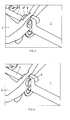
- the bushings 6 can thus be displaced axially along the axis 5 into the area of the electronic module 2, as can be seen from FIG. 3.
- the bushes 6 can be axially displaced further outwards up to their stop, as shown in FIG. 4.
- the outer region of the sleeve 6 comes to lie in the opening 8 of the base plate 1.
- the radial and axial components of the forces acting on the axis 5 can thus be transmitted to the base plate 1 and the electronics module 2 advantageously remains practically free from the influence of these forces.
- the inner region of the sleeve 6 has a rib 6 ′′ as a stop. This comes into abutment in the axial direction against the inner surface of a corresponding recess 9 in the base plate 1 and thus fixes the electronics module 2 in the base plate 1.
- the forces acting on the axis 5 can be conducted into the base plate 1 and thus keep the electronics module 2 practically free of force and on the other hand a fixation or. Locking the electronics module 2 in the base plate causes.
Landscapes
- Health & Medical Sciences (AREA)
- General Health & Medical Sciences (AREA)
- Neurosurgery (AREA)
- Otolaryngology (AREA)
- Physics & Mathematics (AREA)
- Engineering & Computer Science (AREA)
- Acoustics & Sound (AREA)
- Signal Processing (AREA)
- Battery Mounting, Suspending (AREA)
- Prostheses (AREA)
- Casings For Electric Apparatus (AREA)
Abstract
Description
- Die vorliegende Erfindung betrifft ein Gehäuse nach dem Oberbegriff von Anspruch 1.
- Herkömmlicherweise wird beim Aufbau von Gehäusen von Hörhilfen resp. Hörgeräten eine Grundplatte resp. Faceplate eingesetzt, an welches einerseits die Schale, d.h. die äussere Gehäusewand, und andererseits die elektronischen Bauelemente angeordnet werden.
- So wird beispielsweise bei Im-Ohr-Hörgeräten eine Grundplatte verwendet, an welche die individuell für den jeweiligen Träger angepasste Schale befestigt wird. In der Regel erfolgt die Befestigung zwischen der Grundplatte und der an den Träger des Hörgerätes angepassten Schale mittels Verklebung resp. Verschweissung oder durch Herstellung in Lasersintering oder Stereolithographie ganzer Gehäuse für Im-Ohr-Hörgeräte. Die Grundplatte weist dabei eine Öffnung auf, in welche die komplette Elektronik des Gerätes vorteilhaft in Modulform eingesetzt resp. eingeklinkt wird. In diesem Modul ist in der Regel ebenfalls das Batteriefach integriert, welches einen über eine Achse schwenkbar ausgebildeten Batteriedeckel aufweist. Damit lässt sich einfach die Batterie, welche der Versorgung des Moduls mit Energie dient, auswechseln. Diese Auswechslung kann sowohl von Fachleuten wie auch vom Träger des Hörgerätes selbst erfolgen. Der Vorteil dieser Konstruktion liegt darin, dass ein einheitliches Modul für unterschiedliche, in der Regel individuell gefertigte Hörgeräte, eingesetzt werden kann.
- Dabei werden allerdings bedingt durch die Integration der Achse des Batteriedeckels im resp. auf dem Modul alle Kräfte beim Manipulieren des Deckels, beispielsweise beim Schliessen oder Öffnen des Deckels, auf das Modul übertragen. Diese Kräfte können einerseits die elektronischen Komponenten des Moduls direkt beschädigen und andererseits die elektrischen Verbindungen zwischen diesen Komponenten beschädigen. Insbesondere die Kontakte, Leiterbahnen und Drähte des Moduls sind sehr empfindlich auf derartige mechanische Krafteinflüsse.
- Die Aufgabe der vorliegenden Erfindung bestand darin, eine Gehäusekonstruktion für Hörhilfen resp. Hörgeräte zu finden, welche verhindert, dass Kräfte über den geöffneten Batteriedeckel auf die Hauptplatine resp. das Elektronikmodul der Hörhilfe resp. des Hörgerätes übertragen werden.
- Diese Aufgabe wird erfindungsgemäss durch ein Gehäuse mit den Merkmalen nach Anspruch 1 gelöst.
- Weitere erfindungsgemässe Ausführungsformen ergeben sich aus den Merkmalen der Ansprüche 2 bis 6.
- Dadurch, dass die Achse für den Deckel nicht fest oder direkt mit dem Elektronikmodul verbunden ist, sondern über die auf der Achse verschiebbar angeordneten Buchsen mit dem Grundkörper verbindbar ist, werden die über den Deckel auf die Achse übertragenen Kräfte vorteilhaft nicht auf das Elektronikmodul sondern auf den Grundkörper übertragen. Damit bleibt das Elektronikmodul praktisch kräftefrei und die daran resp. darauf angeordneten elektronischen Komponenten können dadurch nicht beeinträchtigt oder beschädigt werden. Dennoch kann das Elektronikmodul in den Grundkörper eingesetzt und ggf. auch wieder daraus entfernt werden, falls es ersetzt oder repariert werden sollte.
- Vorteilhaft weist das Elektronikmodul zur Durchführung der Enden der Achse beidseits einer Öffnung für den Deckel Bohrungen auf, welche einen grösseren Durchmesser aufweisen als der Durchmesser der Achse. Dabei ist der Durchmesser gleich gross oder grösser als der Durchmesser der Endbereiche der Büchsen. Damit können die Büchsen leicht durch diese Bohrungen hindurch nach Aussen zum Grundkörper hin verschoben werden. Wenn bevorzugterweise zwischen der Bohrung und der Achse ein Spiel besteht, so wird der Kraftschluss zwischen Büchse und Elektronikmodul unterbrochen und damit zuverlässig keine axialen und radialen Kräfte von der Achse über die Büchse auf das Elektronikmodul übertragen.
- Die Büchsen können vorzugsweise jeweils ein Anschlagelement, vorzugsweise in Form einer Rippe aufweisen, welches gegen einen entsprechend ausgebildeten Anschlag, vorzugsweise die Fläche einer Ausnehmung, axial bezüglich der Achse in Anschlag bringbar ist.
- Vorzugsweise bestehen die Büchsen aus Kunststoff, Keramik oder Metall. Sie weisen damit sowohl eine hohe Festigkeit wie auch gute Gleiteigenschaften bezüglich der Achse auf.
- Vorzugsweise sind die Ausnehmungen resp. Bohrungen der Grundplatte innerhalb der Grundplatte oder in einem nach Aussen abstehenden Wulst der Grundplatte ausgebildet. In diesem Bereich kann die Grundplatte auch Verstärkungen aufweisen, um die Kräfte optimal aufzunehmen.
- Weiter wird gemäss Anspruch 7 ein Hörgerät resp. Hörhilfe mit einem Gehäuse nach einem der Ansprüche 1 bis 6 beansprucht.
- Weiter wird gemäss Anspruch 8 die Verwendung eines erfindungsgemässen Gehäuses nach einem der Ansprüche 1 bis 6 für Hörhilfen oder Hörgeräte, vorzugsweise für Im-Ohr-Hörgeräte beansprucht. Gerade bei Im-Ohr-Hörgeräten ist die beanspruchte Gehäuseanordnung von Vorteil, da sie sich einfach in sehr kleinen Dimensionen ausführen lässt, wie sie bei diesem Typ von Hörgeräten vorkommen.
- Ein Ausführungsbeispiel der Erfindung wird nachstehend anhand der Zeichnungen noch näher erläutert. Es zeigen
- Fig. 1 die Ansicht eines erfindungsgemäss ausgebildeten Gehäuses im Bereich des eingesetzten Elektronikmoduls;
- Fig. 2 die Ansicht des Gehäuses gemäss Figur 1 mit den Büchsen in der Einsetzposition;
- Fig. 3 die Ansicht nach Figur 2 mit den Büchsen in der ersten Einschiebposition; und
- Fig. 4 die Ansicht nach Figur 2 mit der Büchse in der fertig eingeschobenen Position.
- In Figur 1 ist die Ansicht auf den Bereich eines Gehäuses für Hörhilfen resp. Hörgeräte mit in die Grundplatte 1 eingesetztem Elektronikmodul 2 dargestellt. Die Grundplatte 1 ist rein schematisch als gerader Abschnitt dargestellt, kann aber selbstverständlich auch jede andere geeignete Form aufweisen. Insbesondere kann die äussere Schale des Gehäuses der Hörhilfe die Form des Innenohres aufweisen und die Grundplatte den von Aussen sichtbare resp. nach Aussen aus dem Gehörgang weisenden Teil des Gehäuses bilden.
- Das Elektronikmodul 2 wird in eine in der Grundplatte 1 ausgebildeten Öffnung 3 eingeführt, womit die elektronischen Bauteile des Elektronikmoduls 2 in das Gehäuseinnere der Hörhilfe zu liegen kommen. Gegen Aussen weist auch das Elektronikmodul 2 eine Öffnung 4 auf, welche durch einen schwenkbar angeordneten Deckel (der Übersichtlichkeit halber nicht dargestellt) verschlossen werden kann. In diese Öffnung 4 wird eine Batterie, idR eine Knopfzelle, eingesetzt, welche die elektronischen Komponenten des Elektronikmoduls 2 mit Energie versorgt. Um die Batterie bei Bedarf einfach austauschen zu können, ist der schwenkbar angeordnete Deckel vorgesehen.
- Der Deckel wird an der Achse 5 befestigt, welche quer zur Öffnung 4 verlaufend am Elektronikmodul 2 angeordnet ist. Bei herkömmlichen Elektronikmodulen 2 ist diese Achse 5 direkt in das Elektronikmodul 2 integriert, womit die beim Öffnen und Schliessen über den Deckel auf die Achse wirkende Kräfte nachteilig direkt auf das Elektronikmodul 2 übertragen werden.
- Das erfindungsgemässe Gehäuse weist nun an beiden Enden der Achse 5 positionierte Büchsen 6 auf, wie dies aus der Darstellung nach Figur 2 hervorgeht. Die Achse 5 weist dabei vorzugsweise eine maximale Länge auf, welche der Breite des Elektronikmoduls 2 im Bereich der Achse 5 entspricht. Damit lässt sich das Elektronikmodul 2 einfach in die Öffnung 3 der Grundplatte 1 einschieben resp. einstecken. Vorzugsweise ist am Elektronikmodul 2 oder der Grundplatte 1 ein Vorsprung oder Anschlag ausgebildete, welcher die endgültige Einstecktiefe des Elektronikmoduls 2 definiert.
- Weiter weist das Elektronikmodul 2 im Durchgangsbereich der Achse 5 eine durchgehende Bohrung 7 auf, welche mindestens dem äusseren Durchmesser des äusseren Bereiches 6' der Büchse 6 entspricht, und einen grösseren Durchmesser aufweist als der Durchmesser der Achse 5. Gegenüber den Stirnseiten der Achse 5 sind weiter in der Grundplatte 1 Öffnungen oder Bohrungen 8 ausgebildet, welche dem Durchmesser des äusseren Bereiches 6' der Büchse 6 entsprechen.
- Damit lassen sich die Büchsen 6 axial entlang der Achse 5 nach Aussen in den Bereich des Elektronikmoduls 2 verschieben, wie dies aus Figur 3 hervorgeht.
- Schliesslich lassen sich die Büchsen 6 axial bis an ihren Anschlag noch weiter nach Aussen verschieben, wie dies in Figur 4 dargestellt ist. Dadurch kommt der äussere Bereich der Büchse 6 in die Öffnung 8 der Grundplatte 1 zu liegen. Damit können die radialen und axialen Komponenten der auf die Achse 5 wirkenden Kräfte auf die Grundplatte 1 übertragen werden und das Elektronikmodul 2 bleibt vorteilhaft praktisch frei vom Einfluss dieser Kräfte.
- Der innere Bereich der Büchse 6 weist als Anschlag eine Rippe 6" auf. Diese gelangt in axialer Richtung gegen die Innenfläche einer entsprechenden Ausnehmung 9 der Grundplatte 1 in Anschlag und fixiert damit das Elektronikmodul 2 in der Grundplatte 1.
- Durch diese erfindungsgemässe Anordnung lassen sich einerseits die auf die Achse 5 wirkenden Kräfte in die Grundplatte 1 leiten und damit das Elektronikmodul 2 praktisch kräftefrei halten und andererseits wird damit gleichzeitig eine Fixierung resp. Verriegelung des Elektronikmoduls 2 in der Grundplatte bewirkt.
Claims (8)
- Gehäuse einer Hörhilfe resp. eines Hörgerätes mit einer Grundplatte (1), einer damit verbundenen Gehäuseschale und mit einem Elektronikmodul (2), wobei das Elektronikmodul (2) mindestens eine Halteeinrichtung zur Aufnahme einer Batterie aufweist, welche einen über eine Achse (5) verschwenkbaren Deckel aufweist, dadurch gekennzeichnet, dass die Achse (5) zwei axial über ihr jeweiliges Ende hinaus verschiebbare Büchsen (6) aufweist, welche in entsprechend ausgebildete Ausnehmungen resp. Bohrungen (8) der Grundplatte (1) einschiebbar sind, und damit die Achse mit der Grundplatte (1) verbinden.
- Gehäuse nach Anspruch 1, dadurch gekennzeichnet, dass das Elektronikmodul (2) zur Durchführung der Enden der Achse (5) beidseits einer Öffnung (4) für den Deckel Bohrungen (7) aufweist, welche einen grösseren Durchmesser aufweisen als der Durchmesser der Achse (5), wobei der Durchmesser gleich gross oder grösser als der Durchmesser der Endbereiche (6') der Büchsen (6) ist.
- Gehäuse nach Anspruch 1 oder 2, dadurch gekennzeichnet, dass die Büchsen (6) jeweils ein Anschlagelement, vorzugsweise in Form einer Rippe (6'') aufweisen, welches gegen einen entsprechend ausgebildeten Anschlag, vorzugsweise die Fläche einer Ausnehmung (8), axial bezüglich der Achse (5)in Anschlag bringbar ist.
- Gehäuse nach einem der Ansprüche 1 bis 3, dadurch gekennzeichnet, dass die Büchsen (6) aus Kunststoff, Keramik oder Metall bestehen.
- Gehäuse nach einem der Ansprüche 1 bis 4, dadurch gekennzeichnet, dass die Ausnehmungen resp. Bohrungen (8) der Grundplatte innerhalb der Grundplatte (1) ausgebildete sind oder in einem nach Aussen abstehenden Wulst der Grundplatte (1) ausgebildet sind.
- Gehäuse nach einem der Ansprüche 1 bis 5, dadurch gekennzeichnet, dass die Büchsen (6) in vollständig eingeschobener Position zumindest bereichsweise durch Bereiche des Deckels in geschlossener Position abgedeckt sind, so dass ein axiales Verschieben in Richtung des Deckels verhindert wird.
- Hörgerät resp. Hörhilfe mit einem Gehäuse nach einem der Ansprüche 1 bis 6.
- Verwendung eines Gehäuses nach einem der Ansprüche 1 bis 6 für Hörhilfen oder Hörgeräte, vorzugsweise für Im-Ohr-Hörgeräte.
Priority Applications (5)
| Application Number | Priority Date | Filing Date | Title |
|---|---|---|---|
| DE50304726T DE50304726D1 (de) | 2003-11-21 | 2003-11-21 | Gehäuse für eine Hörhilfe oder ein Hörgerät |
| DK03026777T DK1414270T3 (da) | 2003-11-21 | 2003-11-21 | Hus til et hörehjælpeudstyr hhv. et höreapparat |
| EP03026777A EP1414270B1 (de) | 2003-11-21 | 2003-11-21 | Gehäuse für eine Hörhilfe oder ein Hörgerät |
| US10/768,321 US7043039B2 (en) | 2003-11-21 | 2004-01-30 | Housing for a hearing aid or hearing device respectively |
| CN2004101033719A CN1642361B (zh) | 2003-11-21 | 2004-11-19 | 听音装置的机体、具有该机体的听音装置及该机体的应用 |
Applications Claiming Priority (1)
| Application Number | Priority Date | Filing Date | Title |
|---|---|---|---|
| EP03026777A EP1414270B1 (de) | 2003-11-21 | 2003-11-21 | Gehäuse für eine Hörhilfe oder ein Hörgerät |
Publications (3)
| Publication Number | Publication Date |
|---|---|
| EP1414270A2 true EP1414270A2 (de) | 2004-04-28 |
| EP1414270A3 EP1414270A3 (de) | 2004-05-26 |
| EP1414270B1 EP1414270B1 (de) | 2006-08-23 |
Family
ID=32050171
Family Applications (1)
| Application Number | Title | Priority Date | Filing Date |
|---|---|---|---|
| EP03026777A Expired - Lifetime EP1414270B1 (de) | 2003-11-21 | 2003-11-21 | Gehäuse für eine Hörhilfe oder ein Hörgerät |
Country Status (5)
| Country | Link |
|---|---|
| US (1) | US7043039B2 (de) |
| EP (1) | EP1414270B1 (de) |
| CN (1) | CN1642361B (de) |
| DE (1) | DE50304726D1 (de) |
| DK (1) | DK1414270T3 (de) |
Families Citing this family (1)
| Publication number | Priority date | Publication date | Assignee | Title |
|---|---|---|---|---|
| US20080007217A1 (en) * | 2006-07-06 | 2008-01-10 | Riley Louis F | Method and apparatus for recharging a hearing device |
Family Cites Families (8)
| Publication number | Priority date | Publication date | Assignee | Title |
|---|---|---|---|---|
| US4272591A (en) * | 1980-03-25 | 1981-06-09 | Beltone Electronics Corporation | Electronic apparatus with battery chamber |
| US4570290A (en) * | 1981-07-20 | 1986-02-18 | Hartwell Corporation | Hinge having a laterally outwardly extending flat spring |
| AT372812B (de) * | 1982-04-07 | 1983-11-25 | Viennatone Gmbh | Im ohr hoergeraet |
| US4598177A (en) * | 1985-01-16 | 1986-07-01 | Sears, Roebuck, & Co. | Hearing aid with self-contained battery compartment and volume control |
| DE8621021U1 (de) * | 1986-08-05 | 1988-01-21 | Siemens AG, 1000 Berlin und 8000 München | Scharnier für eine Klappe an einem Hörgerät |
| DK42197A (da) * | 1997-04-15 | 1998-10-16 | Toepholm & Westermann | Kompakt moduleret i-øret høreapparat |
| DE59915251D1 (de) * | 1999-06-16 | 2011-04-07 | Phonak Ag | Hinterohr-hörgerät |
| DE10213847B4 (de) * | 2002-03-27 | 2007-02-01 | Siemens Audiologische Technik Gmbh | Vorrichtung zum Abdecken eines Hörgerätegehäuses |
-
2003
- 2003-11-21 DE DE50304726T patent/DE50304726D1/de not_active Expired - Lifetime
- 2003-11-21 DK DK03026777T patent/DK1414270T3/da active
- 2003-11-21 EP EP03026777A patent/EP1414270B1/de not_active Expired - Lifetime
-
2004
- 2004-01-30 US US10/768,321 patent/US7043039B2/en not_active Expired - Fee Related
- 2004-11-19 CN CN2004101033719A patent/CN1642361B/zh not_active Expired - Fee Related
Also Published As
| Publication number | Publication date |
|---|---|
| US7043039B2 (en) | 2006-05-09 |
| DE50304726D1 (de) | 2006-10-05 |
| EP1414270A3 (de) | 2004-05-26 |
| EP1414270B1 (de) | 2006-08-23 |
| US20050111684A1 (en) | 2005-05-26 |
| CN1642361B (zh) | 2011-01-12 |
| CN1642361A (zh) | 2005-07-20 |
| DK1414270T3 (da) | 2006-11-13 |
Similar Documents
| Publication | Publication Date | Title |
|---|---|---|
| EP1874091A2 (de) | HdO-Hörhilfe mit Batteriefach | |
| DE102019114257B4 (de) | Steckverbinder mit Verriegelungssystem | |
| DE102013106279A1 (de) | Halterahmen für Steckverbindermodule | |
| DE102010021303A1 (de) | Elektrische Steckverbindung, insbesondere Rundsteckverbindung | |
| DE102006016882A1 (de) | Steckverbinder | |
| EP1241386A1 (de) | Steuereinrichtung für Druckmittel | |
| EP2934360B1 (de) | Medizinischer haltearm | |
| EP1414269B1 (de) | Grundplatte mit Elektronikmodul | |
| EP2449302B1 (de) | Kupplungsanordnung | |
| EP1414270B1 (de) | Gehäuse für eine Hörhilfe oder ein Hörgerät | |
| EP1411844B1 (de) | Medizinisches instrument mit zwei teilen mit verbindungsvorrichtung zu deren verbindung | |
| EP1914842B9 (de) | Stecker für Koaxialkabel | |
| DE102012204069B4 (de) | Elektrische Steckerverbindung | |
| DE112022001925T5 (de) | Schneidteil, Haltevorrichtung und Schneidwerkzeug mit einer Anordnung zum Anzeigen der Drehausrichtung zwischen dem Schneidteil und der Haltevorrichtung | |
| DE102006043186B4 (de) | Gelenkeinrichtung | |
| DE102022132333B3 (de) | Halteklemme für eine Leitungsverbindung und Leitungsverbindungseinheit mit einer solchen Halteklemme | |
| EP2198678B1 (de) | Mehrfach-mikro-hf-kontaktanordnung | |
| BE1030480B1 (de) | Festpoliger Kontakteinsatz und Kontakteinsatzanordnung | |
| EP3853621B1 (de) | Formteil zur aufnahme eines c-förmigen magnetfeldkonzentrationselements, magnetfeldkonzentrationsvorrichtung und stromrichter | |
| DE102012102966A1 (de) | Elektrisches Steckerelement mit dehnbarem Kontaktsicherungsorgan | |
| DE19814108B4 (de) | Elektrischer Steckverbinder zur Montage in einem Ausschnitt in einer Wandung | |
| DE102015206452A1 (de) | Gerät mit einem Gehäuse zur Aufnahme einer Leiterplatte | |
| EP1641316B1 (de) | Befestigungsvorrichtung für Betätigungselemente von Hörgeräten resp. Hörhilfen | |
| DE202004000423U1 (de) | Verbindungsanordnung | |
| EP4307484A1 (de) | Anordnung mit einem einpresskontaktelement und mit einer hülse und leistungshalbleitermodul hiermit |
Legal Events
| Date | Code | Title | Description |
|---|---|---|---|
| PUAI | Public reference made under article 153(3) epc to a published international application that has entered the european phase |
Free format text: ORIGINAL CODE: 0009012 |
|
| PUAL | Search report despatched |
Free format text: ORIGINAL CODE: 0009013 |
|
| AK | Designated contracting states |
Kind code of ref document: A2 Designated state(s): AT BE BG CH CY CZ DE DK EE ES FI FR GB GR HU IE IT LI LU MC NL PT RO SE SI SK TR |
|
| AX | Request for extension of the european patent |
Extension state: AL LT LV MK |
|
| AK | Designated contracting states |
Kind code of ref document: A3 Designated state(s): AT BE BG CH CY CZ DE DK EE ES FI FR GB GR HU IE IT LI LU MC NL PT RO SE SI SK TR |
|
| AX | Request for extension of the european patent |
Extension state: AL LT LV MK |
|
| RIC1 | Information provided on ipc code assigned before grant |
Ipc: 7H 04R 25/00 A Ipc: 7E 05D 7/10 B |
|
| 17P | Request for examination filed |
Effective date: 20041117 |
|
| RTI1 | Title (correction) |
Free format text: HOUSING FOR A HEARING PROSTHESIS OR A HEARING AID |
|
| AKX | Designation fees paid |
Designated state(s): CH DE DK LI |
|
| GRAP | Despatch of communication of intention to grant a patent |
Free format text: ORIGINAL CODE: EPIDOSNIGR1 |
|
| GRAS | Grant fee paid |
Free format text: ORIGINAL CODE: EPIDOSNIGR3 |
|
| GRAA | (expected) grant |
Free format text: ORIGINAL CODE: 0009210 |
|
| AK | Designated contracting states |
Kind code of ref document: B1 Designated state(s): CH DE DK LI |
|
| REG | Reference to a national code |
Ref country code: CH Ref legal event code: NV Representative=s name: TROESCH SCHEIDEGGER WERNER AG Ref country code: CH Ref legal event code: EP |
|
| REF | Corresponds to: |
Ref document number: 50304726 Country of ref document: DE Date of ref document: 20061005 Kind code of ref document: P |
|
| REG | Reference to a national code |
Ref country code: DK Ref legal event code: T3 |
|
| PLBE | No opposition filed within time limit |
Free format text: ORIGINAL CODE: 0009261 |
|
| STAA | Information on the status of an ep patent application or granted ep patent |
Free format text: STATUS: NO OPPOSITION FILED WITHIN TIME LIMIT |
|
| 26N | No opposition filed |
Effective date: 20070524 |
|
| PGFP | Annual fee paid to national office [announced via postgrant information from national office to epo] |
Ref country code: DK Payment date: 20101110 Year of fee payment: 8 |
|
| PGFP | Annual fee paid to national office [announced via postgrant information from national office to epo] |
Ref country code: CH Payment date: 20101112 Year of fee payment: 8 Ref country code: DE Payment date: 20101117 Year of fee payment: 8 |
|
| REG | Reference to a national code |
Ref country code: CH Ref legal event code: PL |
|
| REG | Reference to a national code |
Ref country code: DK Ref legal event code: EBP |
|
| PG25 | Lapsed in a contracting state [announced via postgrant information from national office to epo] |
Ref country code: CH Free format text: LAPSE BECAUSE OF NON-PAYMENT OF DUE FEES Effective date: 20111130 Ref country code: LI Free format text: LAPSE BECAUSE OF NON-PAYMENT OF DUE FEES Effective date: 20111130 |
|
| REG | Reference to a national code |
Ref country code: DE Ref legal event code: R119 Ref document number: 50304726 Country of ref document: DE Effective date: 20120601 |
|
| PG25 | Lapsed in a contracting state [announced via postgrant information from national office to epo] |
Ref country code: DK Free format text: LAPSE BECAUSE OF NON-PAYMENT OF DUE FEES Effective date: 20111130 |
|
| PG25 | Lapsed in a contracting state [announced via postgrant information from national office to epo] |
Ref country code: DE Free format text: LAPSE BECAUSE OF NON-PAYMENT OF DUE FEES Effective date: 20120601 |