EP1413689A1 - Method and means for constructing masonry walls - Google Patents
Method and means for constructing masonry walls Download PDFInfo
- Publication number
- EP1413689A1 EP1413689A1 EP20030023026 EP03023026A EP1413689A1 EP 1413689 A1 EP1413689 A1 EP 1413689A1 EP 20030023026 EP20030023026 EP 20030023026 EP 03023026 A EP03023026 A EP 03023026A EP 1413689 A1 EP1413689 A1 EP 1413689A1
- Authority
- EP
- European Patent Office
- Prior art keywords
- spacer
- centering
- blocks
- row
- holes
- Prior art date
- Legal status (The legal status is an assumption and is not a legal conclusion. Google has not performed a legal analysis and makes no representation as to the accuracy of the status listed.)
- Granted
Links
- 238000000034 method Methods 0.000 title claims description 9
- 125000006850 spacer group Chemical group 0.000 claims abstract description 28
- 230000000284 resting effect Effects 0.000 claims abstract 3
- 239000004570 mortar (masonry) Substances 0.000 claims description 17
- 239000000463 material Substances 0.000 claims description 2
- 239000004033 plastic Substances 0.000 claims description 2
- 238000002347 injection Methods 0.000 description 3
- 239000007924 injection Substances 0.000 description 3
- 238000010276 construction Methods 0.000 description 2
- 230000002093 peripheral effect Effects 0.000 description 2
- 239000004743 Polypropylene Substances 0.000 description 1
- 230000001133 acceleration Effects 0.000 description 1
- 230000015572 biosynthetic process Effects 0.000 description 1
- 238000005266 casting Methods 0.000 description 1
- 238000011065 in-situ storage Methods 0.000 description 1
- 238000004519 manufacturing process Methods 0.000 description 1
- -1 polypropylene Polymers 0.000 description 1
- 229920001155 polypropylene Polymers 0.000 description 1
- 230000003014 reinforcing effect Effects 0.000 description 1
- 239000002689 soil Substances 0.000 description 1
- 230000003068 static effect Effects 0.000 description 1
Images




Classifications
-
- E—FIXED CONSTRUCTIONS
- E04—BUILDING
- E04B—GENERAL BUILDING CONSTRUCTIONS; WALLS, e.g. PARTITIONS; ROOFS; FLOORS; CEILINGS; INSULATION OR OTHER PROTECTION OF BUILDINGS
- E04B2/00—Walls, e.g. partitions, for buildings; Wall construction with regard to insulation; Connections specially adapted to walls
- E04B2/02—Walls, e.g. partitions, for buildings; Wall construction with regard to insulation; Connections specially adapted to walls built-up from layers of building elements
- E04B2/14—Walls having cavities in, but not between, the elements, i.e. each cavity being enclosed by at least four sides forming part of one single element
-
- E—FIXED CONSTRUCTIONS
- E04—BUILDING
- E04B—GENERAL BUILDING CONSTRUCTIONS; WALLS, e.g. PARTITIONS; ROOFS; FLOORS; CEILINGS; INSULATION OR OTHER PROTECTION OF BUILDINGS
- E04B2/00—Walls, e.g. partitions, for buildings; Wall construction with regard to insulation; Connections specially adapted to walls
- E04B2/02—Walls, e.g. partitions, for buildings; Wall construction with regard to insulation; Connections specially adapted to walls built-up from layers of building elements
- E04B2002/0202—Details of connections
- E04B2002/0243—Separate connectors or inserts, e.g. pegs, pins or keys
Definitions
- the present invention relates to a method and means for constructing masonry walls of prefabricated cementitious blocks.
- the method currently used to construct masonry walls of cementitious blocks is based essentially on exhausting slow manual work.
- the (qualified) bricklayer applies to the upper face of a horizontal succession of blocks relatively thick runs of mortar along two sides of the blocks, which have already received a layer of mortar applied to one of their lateral faces to obtain a lateral bond between one block and the next.
- the bricklayer places on the resultant row of blocks a row of blocks offset from the underlying row, this operation involving:
- the main object of the present invention is to provide a method and means which represent an innovation compared with the aforedescribed method and enable:
- the cementitious blocks 1 with which a wall is to be erected are widely known and standardized; they are similar in shape to a right (rectangular) parallelepiped having two parallel through holes 2, 3 for lightening purposes separated by an intermediate internal wall 4.
- the holes are conical or tapered.
- a row of blocks 1 with their minor faces side by side is laid on a predisposed cementitious bed or similar cementitious surface. This row of blocks forms the base from which the wall is erected by superposing rows of mutually offset blocks.
- a spacer/centering element D (described in detail hereinafter) is positioned on the base blocks, i.e. the blocks of the lower row, in correspondence with the openings of each of their holes 2, 3.
- This spacer/centering element D of annular shape (moulded in plastic material, for example filled polypropylene made fireproof) comprises, preferably peripherally and/or in proximity to the periphery, support feet 5 for example of cylindrical or pin shape, which rest along the contour of these openings, these latter having rectilinear sides connected together by arcuate corners (see Figure 5).
- the spacer/centering element D also presents (in this example) on one side ( Figure 1) a first peripheral skirt 6 which follows the contour of the hole in the block and enters the hole itself (via said opening). In this manner the spacer/centering element D rests on and is centered about the underlying block.
- a nozzle 8 is provided having a wide and narrow exit mouth 9 (similar to the interspaces) and fed with mortar from a vessel 10 by means of a screw feeder 13; the feed can be controlled by a valve (not shown).
- a profiled smoother bar 11 is provided to the side of the nozzle 8 to the side of the nozzle 8 to the side of the nozzle 8 to the side of the nozzle 8 to the side of the nozzle 8 there is provided a profiled smoother bar 11 with which the external face of the injected mortar layer is finished.
- the skirts 6, 7 of the spacer/centering element D comprise rounded corner portions 6a, 7a with a tapered lead-in end to provide effective centering, and intermediate parts 6b, 7b of undulated shape.
- the undulations form channels 13 ( Figure 6) through which the mortar also reaches the sides of these holes, to give rise to the formation of inward projections when the mortar has set.
- the injected mortar solidifies to replace the support feet 5 for the static support of the wall.
- the wall erection can be continued until completion by proceeding in the aforedescribed manner.
- the undulations can be dispensed with, the centering function being entrusted to only the corner portions 6a, 6b.
- the spacer/centering element D defines an aperture A to enable possible passage of reinforcing rods for constructing pillars obtainable, as in the known art, by casting cementitious mortar into the holes 2, 3 of the blocks, which are virtually superposed in the erected wall.
Landscapes
- Engineering & Computer Science (AREA)
- Architecture (AREA)
- Physics & Mathematics (AREA)
- Electromagnetism (AREA)
- Civil Engineering (AREA)
- Structural Engineering (AREA)
- Conveying And Assembling Of Building Elements In Situ (AREA)
- Drilling And Exploitation, And Mining Machines And Methods (AREA)
- Retaining Walls (AREA)
- Devices For Post-Treatments, Processing, Supply, Discharge, And Other Processes (AREA)
Abstract
Description
- The present invention relates to a method and means for constructing masonry walls of prefabricated cementitious blocks.
- The method currently used to construct masonry walls of cementitious blocks is based essentially on exhausting slow manual work. In this respect, on examining this method in detail it will be noted that the (qualified) bricklayer applies to the upper face of a horizontal succession of blocks relatively thick runs of mortar along two sides of the blocks, which have already received a layer of mortar applied to one of their lateral faces to obtain a lateral bond between one block and the next. The bricklayer places on the resultant row of blocks a row of blocks offset from the underlying row, this operation involving:
- I. careful horizontal and vertical positioning of the individual blocks, and
- II. falling of the excess mortar, which not only soils the wall under erection but also constitutes an irrecoverable wastage, which is disposed of.
- The main object of the present invention is to provide a method and means which represent an innovation compared with the aforedescribed method and enable:
- A. a definite acceleration in the construction of the masonry wall;
- B. a simplification of this construction such that it can be carried out by unqualified personnel;
- C. a considerable saving in mortar consequent on the practical reduction in wastage;
- D. complete verticality of the masonry wall obtained.
- These and further objects of the present invention are attained by the method and means in accordance with the accompanying claims.
- The invention will be more apparent from the ensuing detailed description of preferred embodiments thereof provided by way of non-limiting example with reference to the accompanying drawings, in which:
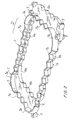
- Figure 1 is a perspective view of a spacer/centering element representative of the essence of the invention, the view showing one side of said spacer/centering element;
- Figure 2 is a perspective view of the spacer/centering element taken on the opposite side;
- Figure 3 is a schematic side view of three cementitious blocks partially shown by dashed lines, with an interposed spacer/centering element prior to injection of the consolidating mortar;
- Figure 4 is a perspective view of a number of blocks arranged with the spacer/centering elements located on the holes of these blocks;
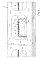
- Figure 5 is a perspective view from above of a partially reproduced block, the view showing the position of the underlying spacer/centering element in situ;
- Figure 6 is a schematic view showing the finishing operation by injecting mortar into the interspaces between blocks using an injection machine schematically reproduced.
- With reference to the figures, the
cementitious blocks 1 with which a wall is to be erected are widely known and standardized; they are similar in shape to a right (rectangular) parallelepiped having two parallel throughholes internal wall 4. The holes are conical or tapered. - A row of
blocks 1 with their minor faces side by side is laid on a predisposed cementitious bed or similar cementitious surface. This row of blocks forms the base from which the wall is erected by superposing rows of mutually offset blocks. - A spacer/centering element D (described in detail hereinafter) is positioned on the base blocks, i.e. the blocks of the lower row, in correspondence with the openings of each of their
holes feet 5 for example of cylindrical or pin shape, which rest along the contour of these openings, these latter having rectilinear sides connected together by arcuate corners (see Figure 5). The spacer/centering element D also presents (in this example) on one side (Figure 1) a firstperipheral skirt 6 which follows the contour of the hole in the block and enters the hole itself (via said opening). In this manner the spacer/centering element D rests on and is centered about the underlying block. - On the row of base blocks arranged with the spacer/centering elements, without applying mortar the operator lays in an offset arrangement a second row of blocks, into the lower hole openings of which there is inserted a second skirt similar to the first but having a smaller contour substantially offset from said
first skirt 6 by about the same amount as the blocks of the second row are offset from the underlying blocks. - This achieves verticalized centering of said second row of blocks. The blocks of this second row rest on the top of said
peripheral feet 5 of the spacer/centering elements D. It is apparent that each of these feet acts as a support and spacer between one row and another of the blocks, to hence obtain the horizontal interspaces A between one row of blocks and the next. - When this second row of blocks has been superposed dry, i.e. without mortar, the spacer/centering elements D are placed in position (as already stated) in the upper openings of the
holes support feet 7 most loaded by the overlying weight. After this, mortar is injected into both the horizontal and vertical interspaces. - For the injection, a
nozzle 8 is provided having a wide and narrow exit mouth 9 (similar to the interspaces) and fed with mortar from avessel 10 by means of ascrew feeder 13; the feed can be controlled by a valve (not shown). To the side of thenozzle 8 there is provided a profiledsmoother bar 11 with which the external face of the injected mortar layer is finished. - As can be seen from the figures showing the spacer/centering element D, the
skirts rounded corner portions 6a, 7a with a tapered lead-in end to provide effective centering, andintermediate parts - The injected mortar solidifies to replace the
support feet 5 for the static support of the wall. - When one wall height has been finished, the wall erection can be continued until completion by proceeding in the aforedescribed manner.
- Finally it should be noted that in order to enable the blocks to be removed from their production moulds, their
holes skirts - In a variant of the invention the undulations can be dispensed with, the centering function being entrusted to only the
corner portions 6a, 6b. - The spacer/centering element D defines an aperture A to enable possible passage of reinforcing rods for constructing pillars obtainable, as in the known art, by casting cementitious mortar into the
holes
Claims (7)
- A method for constructing a wall with prefabricated cementitious blocks in the form substantially of a right prism and provided with through lightening holes, which extend vertically in the constructed wall, in which the blocks are arranged offset from row to row, characterised by zonally resting, on the contour of the openings in the through holes of the blocks of one row, spacer/centering elements provided with first parts engaging in said holes for the purpose of centering said elements, on said one row there being superposed a second row of blocks to zonally rest on said spacer/centering elements, which are provided with second parts engaging in the holes of said second row for the purpose of centering the blocks of the second row, said operations involving said spacer/centering elements being repeated until at least a part of the wall has been erected, in the wall or its thus erected part there appearing interspaces (F) between the rows of blocks, which are sealed by injecting mortar thereinto.
- A spacer/centering element for implementing the method claimed in the preceding claim, characterised by comprising, preferably on its periphery and/or close thereto, feet (5) as zonal resting intermediaries for blocks (1) pertaining to two superposed rows and, on one side thereof, first centering means (6a), for engaging a hole (2, 3) in a block (1) and, on the opposite side thereof, second centering means (7a) offset from the first and arranged to engage a hole in an overlying block.
- A spacer/centering element as claimed in claim 2, wherein the first and second centering means (6a, 6b) are skirts (6, 7) or parts thereof shaped in accordance with at least part of the profile of the hole (2, 3) of the block (1) in which they are to engage.
- A spacer/centering element as claimed in claims 2 and 3, wherein the feet (5) are pin shaped and are at least partly disposed along the outer contour of said element.
- A spacer/centering element as claimed in the preceding claims, wherein the skirts (6, 7) comprise undulating intermediate parts or portions (6b, 7b) to enable injected mortar to also pass into the interior of the holes (2, 3) in the blocks when the spacer/centering element has been mounted.
- A spacer/centering element as claimed in the preceding claims, characterised by bounding a central aperture.
- A spacer/centering element as claimed in the preceding claims, characterised by being moulded of fireproof plastic material.
Applications Claiming Priority (2)
| Application Number | Priority Date | Filing Date | Title |
|---|---|---|---|
| IT002278A ITMI20022278A1 (en) | 2002-10-25 | 2002-10-25 | METHOD AND MEANS FOR THE EXECUTION OF MASONRY |
| ITMI20022278 | 2002-10-25 |
Publications (2)
| Publication Number | Publication Date |
|---|---|
| EP1413689A1 true EP1413689A1 (en) | 2004-04-28 |
| EP1413689B1 EP1413689B1 (en) | 2006-04-05 |
Family
ID=32051237
Family Applications (1)
| Application Number | Title | Priority Date | Filing Date |
|---|---|---|---|
| EP03023026A Expired - Lifetime EP1413689B1 (en) | 2002-10-25 | 2003-10-13 | Method and means for constructing masonry walls |
Country Status (5)
| Country | Link |
|---|---|
| US (1) | US20050016120A1 (en) |
| EP (1) | EP1413689B1 (en) |
| AT (1) | ATE322590T1 (en) |
| DE (1) | DE60304415T2 (en) |
| IT (1) | ITMI20022278A1 (en) |
Families Citing this family (2)
| Publication number | Priority date | Publication date | Assignee | Title |
|---|---|---|---|---|
| US20110139410A1 (en) * | 2009-12-16 | 2011-06-16 | Lennox International, Inc. | Floating Coil Heat Exchanger |
| FR2966454B1 (en) * | 2010-10-26 | 2014-06-13 | Chryso | DEACTIVATING DRY ELIMINABLE SURFACE |
Citations (2)
| Publication number | Priority date | Publication date | Assignee | Title |
|---|---|---|---|---|
| US4091587A (en) * | 1977-02-14 | 1978-05-30 | Depka Charles W | Cement block wall |
| DE3507531A1 (en) * | 1985-03-04 | 1986-09-04 | Kasamentbau GmbH & Co KG, 4500 Osnabrück | Process for producing cast-stone walls, and building elements for this purpose |
Family Cites Families (2)
| Publication number | Priority date | Publication date | Assignee | Title |
|---|---|---|---|---|
| US5159795A (en) * | 1990-07-13 | 1992-11-03 | Colen William J | Wall construction and spacer for use therewith |
| US5351457A (en) * | 1990-07-13 | 1994-10-04 | Colen William J | Wall construction and spacer for use therewith |
-
2002
- 2002-10-25 IT IT002278A patent/ITMI20022278A1/en unknown
-
2003
- 2003-10-13 AT AT03023026T patent/ATE322590T1/en not_active IP Right Cessation
- 2003-10-13 EP EP03023026A patent/EP1413689B1/en not_active Expired - Lifetime
- 2003-10-13 DE DE60304415T patent/DE60304415T2/en not_active Expired - Fee Related
- 2003-10-15 US US10/684,425 patent/US20050016120A1/en not_active Abandoned
Patent Citations (2)
| Publication number | Priority date | Publication date | Assignee | Title |
|---|---|---|---|---|
| US4091587A (en) * | 1977-02-14 | 1978-05-30 | Depka Charles W | Cement block wall |
| DE3507531A1 (en) * | 1985-03-04 | 1986-09-04 | Kasamentbau GmbH & Co KG, 4500 Osnabrück | Process for producing cast-stone walls, and building elements for this purpose |
Also Published As
| Publication number | Publication date |
|---|---|
| US20050016120A1 (en) | 2005-01-27 |
| EP1413689B1 (en) | 2006-04-05 |
| DE60304415D1 (en) | 2006-05-18 |
| DE60304415T2 (en) | 2006-11-16 |
| ATE322590T1 (en) | 2006-04-15 |
| ITMI20022278A1 (en) | 2004-04-26 |
Similar Documents
| Publication | Publication Date | Title |
|---|---|---|
| AU607007B2 (en) | Frames for constructing pavement boards | |
| US5597591A (en) | Apparatus for the production of concrete paving stones | |
| US4060948A (en) | Structural frame for a building | |
| EP1413689B1 (en) | Method and means for constructing masonry walls | |
| US5029804A (en) | In situ brick or block making formwork | |
| US10532488B2 (en) | Method and mold for retaining wall corner and column blocks | |
| KR102214348B1 (en) | the improved PC panel unit manufacturing device | |
| CN115162732A (en) | Construction method of independent special-shaped bare concrete column | |
| JPH05278022A (en) | Molding method of hollow precast concrete member | |
| RU2097509C1 (en) | Shifted formwork mould for erection of wall blocks | |
| GB1604661A (en) | Method and apparatus for making blocks | |
| JPH0419135Y2 (en) | ||
| JPH0745688Y2 (en) | Block for adjusting concrete thickness of slab | |
| JPH05192915A (en) | Pc concrete panel | |
| CN219686020U (en) | Wall column barrel pressing die | |
| JPH0925706A (en) | Horizontal floor with groove, its formation method, and material used for its formation | |
| JP2980792B2 (en) | Column and concrete slab joining method | |
| WO1999025933A1 (en) | Attached decorative stones | |
| JP3024207U (en) | Building blocks | |
| DE2236463A1 (en) | WALL CONSTRUCTION AND METHOD OF MANUFACTURING IT | |
| KR20100034197A (en) | Cast of concrete block | |
| JP2003096792A (en) | Mat foundation construction block and construction method of mat foundation | |
| KR200172614Y1 (en) | Implement of punishment for manufacturing a reinforcing rod supporter | |
| RU33537U1 (en) | FORM FOR PRODUCTION OF CONSTRUCTION PRODUCTS USING A HAND VIBRO-TOOL (OPTIONS) | |
| CN114261015A (en) | EPS module concrete frame infilled wall construction process |
Legal Events
| Date | Code | Title | Description |
|---|---|---|---|
| PUAI | Public reference made under article 153(3) epc to a published international application that has entered the european phase |
Free format text: ORIGINAL CODE: 0009012 |
|
| AK | Designated contracting states |
Kind code of ref document: A1 Designated state(s): AT BE BG CH CY CZ DE DK EE ES FI FR GB GR HU IE IT LI LU MC NL PT RO SE SI SK TR |
|
| AX | Request for extension of the european patent |
Extension state: AL LT LV MK |
|
| 17P | Request for examination filed |
Effective date: 20040804 |
|
| AKX | Designation fees paid |
Designated state(s): AT BE BG CH CY CZ DE DK EE ES FI FR GB GR HU IE IT LI LU MC NL PT RO SE SI SK TR |
|
| AXX | Extension fees paid |
Extension state: MK Payment date: 20040804 Extension state: LT Payment date: 20040804 Extension state: LV Payment date: 20040804 Extension state: AL Payment date: 20040804 |
|
| 17Q | First examination report despatched |
Effective date: 20050315 |
|
| GRAP | Despatch of communication of intention to grant a patent |
Free format text: ORIGINAL CODE: EPIDOSNIGR1 |
|
| GRAS | Grant fee paid |
Free format text: ORIGINAL CODE: EPIDOSNIGR3 |
|
| GRAA | (expected) grant |
Free format text: ORIGINAL CODE: 0009210 |
|
| AK | Designated contracting states |
Kind code of ref document: B1 Designated state(s): AT BE BG CH CY CZ DE DK EE ES FI FR GB GR HU IE IT LI LU MC NL PT RO SE SI SK TR |
|
| AX | Request for extension of the european patent |
Extension state: AL LT LV MK |
|
| PG25 | Lapsed in a contracting state [announced via postgrant information from national office to epo] |
Ref country code: IT Free format text: LAPSE BECAUSE OF FAILURE TO SUBMIT A TRANSLATION OF THE DESCRIPTION OR TO PAY THE FEE WITHIN THE PRESCRIBED TIME-LIMIT;WARNING: LAPSES OF ITALIAN PATENTS WITH EFFECTIVE DATE BEFORE 2007 MAY HAVE OCCURRED AT ANY TIME BEFORE 2007. THE CORRECT EFFECTIVE DATE MAY BE DIFFERENT FROM THE ONE RECORDED. Effective date: 20060405 Ref country code: RO Free format text: LAPSE BECAUSE OF FAILURE TO SUBMIT A TRANSLATION OF THE DESCRIPTION OR TO PAY THE FEE WITHIN THE PRESCRIBED TIME-LIMIT Effective date: 20060405 Ref country code: CZ Free format text: LAPSE BECAUSE OF FAILURE TO SUBMIT A TRANSLATION OF THE DESCRIPTION OR TO PAY THE FEE WITHIN THE PRESCRIBED TIME-LIMIT Effective date: 20060405 Ref country code: FI Free format text: LAPSE BECAUSE OF FAILURE TO SUBMIT A TRANSLATION OF THE DESCRIPTION OR TO PAY THE FEE WITHIN THE PRESCRIBED TIME-LIMIT Effective date: 20060405 Ref country code: SI Free format text: LAPSE BECAUSE OF FAILURE TO SUBMIT A TRANSLATION OF THE DESCRIPTION OR TO PAY THE FEE WITHIN THE PRESCRIBED TIME-LIMIT Effective date: 20060405 Ref country code: CH Free format text: LAPSE BECAUSE OF FAILURE TO SUBMIT A TRANSLATION OF THE DESCRIPTION OR TO PAY THE FEE WITHIN THE PRESCRIBED TIME-LIMIT Effective date: 20060405 Ref country code: LI Free format text: LAPSE BECAUSE OF FAILURE TO SUBMIT A TRANSLATION OF THE DESCRIPTION OR TO PAY THE FEE WITHIN THE PRESCRIBED TIME-LIMIT Effective date: 20060405 Ref country code: NL Free format text: LAPSE BECAUSE OF FAILURE TO SUBMIT A TRANSLATION OF THE DESCRIPTION OR TO PAY THE FEE WITHIN THE PRESCRIBED TIME-LIMIT Effective date: 20060405 Ref country code: AT Free format text: LAPSE BECAUSE OF FAILURE TO SUBMIT A TRANSLATION OF THE DESCRIPTION OR TO PAY THE FEE WITHIN THE PRESCRIBED TIME-LIMIT Effective date: 20060405 Ref country code: BE Free format text: LAPSE BECAUSE OF FAILURE TO SUBMIT A TRANSLATION OF THE DESCRIPTION OR TO PAY THE FEE WITHIN THE PRESCRIBED TIME-LIMIT Effective date: 20060405 Ref country code: SK Free format text: LAPSE BECAUSE OF FAILURE TO SUBMIT A TRANSLATION OF THE DESCRIPTION OR TO PAY THE FEE WITHIN THE PRESCRIBED TIME-LIMIT Effective date: 20060405 |
|
| REG | Reference to a national code |
Ref country code: GB Ref legal event code: FG4D |
|
| REG | Reference to a national code |
Ref country code: CH Ref legal event code: EP |
|
| REG | Reference to a national code |
Ref country code: IE Ref legal event code: FG4D |
|
| REF | Corresponds to: |
Ref document number: 60304415 Country of ref document: DE Date of ref document: 20060518 Kind code of ref document: P |
|
| PG25 | Lapsed in a contracting state [announced via postgrant information from national office to epo] |
Ref country code: SE Free format text: LAPSE BECAUSE OF FAILURE TO SUBMIT A TRANSLATION OF THE DESCRIPTION OR TO PAY THE FEE WITHIN THE PRESCRIBED TIME-LIMIT Effective date: 20060705 Ref country code: DK Free format text: LAPSE BECAUSE OF FAILURE TO SUBMIT A TRANSLATION OF THE DESCRIPTION OR TO PAY THE FEE WITHIN THE PRESCRIBED TIME-LIMIT Effective date: 20060705 |
|
| PG25 | Lapsed in a contracting state [announced via postgrant information from national office to epo] |
Ref country code: ES Free format text: LAPSE BECAUSE OF FAILURE TO SUBMIT A TRANSLATION OF THE DESCRIPTION OR TO PAY THE FEE WITHIN THE PRESCRIBED TIME-LIMIT Effective date: 20060716 |
|
| PG25 | Lapsed in a contracting state [announced via postgrant information from national office to epo] |
Ref country code: PT Free format text: LAPSE BECAUSE OF FAILURE TO SUBMIT A TRANSLATION OF THE DESCRIPTION OR TO PAY THE FEE WITHIN THE PRESCRIBED TIME-LIMIT Effective date: 20060905 |
|
| PGFP | Annual fee paid to national office [announced via postgrant information from national office to epo] |
Ref country code: DE Payment date: 20060915 Year of fee payment: 4 |
|
| LTIE | Lt: invalidation of european patent or patent extension |
Effective date: 20060405 |
|
| NLV1 | Nl: lapsed or annulled due to failure to fulfill the requirements of art. 29p and 29m of the patents act | ||
| PG25 | Lapsed in a contracting state [announced via postgrant information from national office to epo] |
Ref country code: IE Free format text: LAPSE BECAUSE OF NON-PAYMENT OF DUE FEES Effective date: 20061013 |
|
| REG | Reference to a national code |
Ref country code: CH Ref legal event code: PL |
|
| PGFP | Annual fee paid to national office [announced via postgrant information from national office to epo] |
Ref country code: FR Payment date: 20061025 Year of fee payment: 4 |
|
| PG25 | Lapsed in a contracting state [announced via postgrant information from national office to epo] |
Ref country code: MC Free format text: LAPSE BECAUSE OF NON-PAYMENT OF DUE FEES Effective date: 20061031 |
|
| ET | Fr: translation filed | ||
| PLBE | No opposition filed within time limit |
Free format text: ORIGINAL CODE: 0009261 |
|
| STAA | Information on the status of an ep patent application or granted ep patent |
Free format text: STATUS: NO OPPOSITION FILED WITHIN TIME LIMIT |
|
| 26N | No opposition filed |
Effective date: 20070108 |
|
| PG25 | Lapsed in a contracting state [announced via postgrant information from national office to epo] |
Ref country code: GR Free format text: LAPSE BECAUSE OF FAILURE TO SUBMIT A TRANSLATION OF THE DESCRIPTION OR TO PAY THE FEE WITHIN THE PRESCRIBED TIME-LIMIT Effective date: 20060706 |
|
| GBPC | Gb: european patent ceased through non-payment of renewal fee |
Effective date: 20071013 |
|
| PG25 | Lapsed in a contracting state [announced via postgrant information from national office to epo] |
Ref country code: BG Free format text: LAPSE BECAUSE OF FAILURE TO SUBMIT A TRANSLATION OF THE DESCRIPTION OR TO PAY THE FEE WITHIN THE PRESCRIBED TIME-LIMIT Effective date: 20060705 Ref country code: EE Free format text: LAPSE BECAUSE OF FAILURE TO SUBMIT A TRANSLATION OF THE DESCRIPTION OR TO PAY THE FEE WITHIN THE PRESCRIBED TIME-LIMIT Effective date: 20060405 |
|
| PG25 | Lapsed in a contracting state [announced via postgrant information from national office to epo] |
Ref country code: HU Free format text: LAPSE BECAUSE OF FAILURE TO SUBMIT A TRANSLATION OF THE DESCRIPTION OR TO PAY THE FEE WITHIN THE PRESCRIBED TIME-LIMIT Effective date: 20061006 Ref country code: TR Free format text: LAPSE BECAUSE OF FAILURE TO SUBMIT A TRANSLATION OF THE DESCRIPTION OR TO PAY THE FEE WITHIN THE PRESCRIBED TIME-LIMIT Effective date: 20060405 Ref country code: LU Free format text: LAPSE BECAUSE OF NON-PAYMENT OF DUE FEES Effective date: 20061013 Ref country code: DE Free format text: LAPSE BECAUSE OF NON-PAYMENT OF DUE FEES Effective date: 20080501 |
|
| REG | Reference to a national code |
Ref country code: FR Ref legal event code: ST Effective date: 20080630 |
|
| PG25 | Lapsed in a contracting state [announced via postgrant information from national office to epo] |
Ref country code: GB Free format text: LAPSE BECAUSE OF NON-PAYMENT OF DUE FEES Effective date: 20071013 Ref country code: CY Free format text: LAPSE BECAUSE OF FAILURE TO SUBMIT A TRANSLATION OF THE DESCRIPTION OR TO PAY THE FEE WITHIN THE PRESCRIBED TIME-LIMIT Effective date: 20060405 |
|
| PG25 | Lapsed in a contracting state [announced via postgrant information from national office to epo] |
Ref country code: FR Free format text: LAPSE BECAUSE OF NON-PAYMENT OF DUE FEES Effective date: 20071031 |