EP1413048B1 - Method for controlling a variable-reluctance machine - Google Patents
Method for controlling a variable-reluctance machine Download PDFInfo
- Publication number
- EP1413048B1 EP1413048B1 EP02767580A EP02767580A EP1413048B1 EP 1413048 B1 EP1413048 B1 EP 1413048B1 EP 02767580 A EP02767580 A EP 02767580A EP 02767580 A EP02767580 A EP 02767580A EP 1413048 B1 EP1413048 B1 EP 1413048B1
- Authority
- EP
- European Patent Office
- Prior art keywords
- machine
- switch
- switches
- network
- control method
- Prior art date
- Legal status (The legal status is an assumption and is not a legal conclusion. Google has not performed a legal analysis and makes no representation as to the accuracy of the status listed.)
- Expired - Fee Related
Links
Images


Classifications
-
- H—ELECTRICITY
- H02—GENERATION; CONVERSION OR DISTRIBUTION OF ELECTRIC POWER
- H02P—CONTROL OR REGULATION OF ELECTRIC MOTORS, ELECTRIC GENERATORS OR DYNAMO-ELECTRIC CONVERTERS; CONTROLLING TRANSFORMERS, REACTORS OR CHOKE COILS
- H02P9/00—Arrangements for controlling electric generators for the purpose of obtaining a desired output
- H02P9/40—Arrangements for controlling electric generators for the purpose of obtaining a desired output by variation of reluctance of magnetic circuit of generator
-
- H—ELECTRICITY
- H02—GENERATION; CONVERSION OR DISTRIBUTION OF ELECTRIC POWER
- H02P—CONTROL OR REGULATION OF ELECTRIC MOTORS, ELECTRIC GENERATORS OR DYNAMO-ELECTRIC CONVERTERS; CONTROLLING TRANSFORMERS, REACTORS OR CHOKE COILS
- H02P2101/00—Special adaptation of control arrangements for generators
- H02P2101/45—Special adaptation of control arrangements for generators for motor vehicles, e.g. car alternators
Landscapes
- Engineering & Computer Science (AREA)
- Power Engineering (AREA)
- Control Of Eletrric Generators (AREA)
- Control Of Electric Motors In General (AREA)
- Control Of Charge By Means Of Generators (AREA)
Description
La présente invention est relative à un procédé de commande d'une machine électrique polyphasée dont l'inductance des bobinages est exploitable. On entend par exploitable les bobinages dont la constante de temps électrique est supérieure à la période de découpage générée par le procédé de commande.The present invention relates to a method of controlling a polyphase electrical machine whose inductance of windings is exploitable. Explosable is understood to mean coils whose electrical time constant is greater than the switching period generated by the control method.
Plus particulièrement, l'invention concerne un procédé de commande pour une machine électrique à réluctance variable qui permet d'exploiter l'énergie stockée dans les bobinages inductifs de la machine électrique, et ce, en fonction de divers états de fonctionnement de la machine.More particularly, the invention relates to a control method for a variable reluctance electrical machine that makes it possible to exploit the energy stored in the inductive windings of the electric machine, and this, according to various operating states of the machine.
Ainsi, à partir d'une machine électrique à réluctance variable, ce procédé de commande doit permettre d'assurer tout ou partie des fonctions suivantes :
- réaliser une fonction démarrage de la machine électrique à partir d'un réseau primaire d'alimentation constitué par exemple par une batterie,
- réaliser une fonction générateur sur le réseau primaire,
- réaliser une fonction générateur sur au moins un réseau secondaire, constitué par exemple par une batterie,
- réaliser une fonction alimentation d'au moins un réseau secondaire à partir du réseau primaire,
- réaliser une fonction charge ou recharge d'au moins une batterie d'accumulateurs à partir d'au moins un réseau secondaire,
- réaliser une fonction d'alimentation primaire à partir d'au moins un réseau secondaire.
- perform a start function of the electric machine from a primary power supply network constituted for example by a battery,
- perform a generator function on the primary network,
- performing a generator function on at least one secondary network, constituted for example by a battery,
- performing a supply function of at least one secondary network from the primary network,
- performing a charging or recharging function of at least one accumulator battery from at least one secondary network,
- perform a primary power function from at least one secondary network.
On connaît notamment des machines à réluctance variable comportant au moins un bobinage inductif, le bobinage inductif étant relié à un réseau primaire d'alimentation en énergie électrique par l'intermédiaire d'un dispositif de commande comprenant, entre un point de connexion du bobinage considéré et des bornes du réseau primaire, au moins un demi-pont d'un variateur adapté à la commande de ladite machine, ce demi-pont étant formé par des premier et second interrupteurs commandés, les premier et second interrupteurs pouvant occuper chacun un état électrique passant ou ouvert. Une telle machine à réluctance est par exemple divulguée dans le document
Ces machines donnent toute satisfaction d'un point de vue technique, mais leur procédé de commande ne permet pas d'exploiter l'énergie électrique emmagasinée dans les bobinages.These machines are satisfactory from a technical point of view, but their control method does not exploit the electrical energy stored in the windings.
La présente invention a notamment pour but de pallier cet inconvénient.The present invention is intended to overcome this disadvantage.
A cet effet, un procédé de commande d'une machine du genre en question est caractérisé en ce que :
- on relie le point de connexion dudit bobinage à au moins un troisième interrupteur de déviation commandé pouvant occuper un état électrique ouvert ou un état électrique passant, ce troisième interrupteur étant relié à au moins un réseau secondaire d'alimentation électrique,
- on associe l'état électrique du troisième interrupteur à celui du demi-pont, de telle manière que l'énergie électrique stockée dans le bobinage inductif de la machine soit retransmise au réseau principal et/ou au réseau secondaire,
- la commande du troisième interrupteur relié à un premier réseau secondaire est affectée de manière exclusive par rapport à celle, d'un autre troisième interrupteur relié entre le point de connection dudit bobinage et un deuxième réseau secondaire.
- the connection point of said winding is connected to at least one third controlled deflection switch which can occupy an open electrical state or a passing electrical state, this third switch being connected to at least one secondary power supply network,
- the electrical state of the third switch is associated with that of the half-bridge, so that the electrical energy stored in the inductive winding of the machine is retransmitted to the main network and / or the secondary network,
- the control of the third switch connected to a first secondary network is assigned exclusively to that of another third switch connected between the connection point of said winding and a second secondary network.
Grâce à ces dispositions, on utilise les bobinages inductifs de la machine à réluctance variable comme autant d'éléments de stockage d'énergie (source de courant) afin de pouvoir réaliser des échanges d'énergie en- tre les divers réseaux ou entre la machine et les divers réseaux.Thanks to these arrangements, the inductive coils of the variable reluctance machine are used as energy storage elements (current source) in order to be able to carry out energy exchanges. the various networks or between the machine and the various networks.
Dans des modes de réalisation préférés de l'invention, on peut éventuellement avoir recours en outre à l'une et/ou à l'autre des dispositions suivantes :
- la commande d'un troisième interrupteur est effectuée de manière exclusive par rapport à celle des premier et second interrupteurs,
- on introduit un temps mort entre les commandes des troisièmes interrupteurs, afin d'éviter des courts circuits entre le réseau primaire et les réseaux secondaires d'alimentation électrique.
- the control of a third switch is performed exclusively with respect to that of the first and second switches,
- a dead time is introduced between the controls of the third switches, in order to avoid short circuits between the primary network and the secondary power supply networks.
Selon un autre aspect de l'invention, celle-ci consiste en l'utilisation du procédé de commande pour réaliser un convertisseur statique élévateur ou abaisseur de tension, ou un variateur et convertisseur simultané.According to another aspect of the invention, it consists in the use of the control method for producing a static up-converter or down-converter, or a simultaneous converter and converter.
Selon encore un autre aspect de l'invention, celle-ci consiste en l'utilisation de ce même procédé de commande à un alterno-démarreur à réluctance variable bi-tension.According to yet another aspect of the invention, it consists in the use of this same control method to a two-voltage variable reluctance alternator-starter.
D'autres caractéristiques et avantages de l'invention apparaîtront au cours de la description suivante d'une de ses formes de réalisation, donnée à titre d'exemple non limitatif, en regard des dessins joints.Other features and advantages of the invention will become apparent from the following description of one of its embodiments, given by way of non-limiting example, with reference to the accompanying drawings.
Sur les dessins :
- la
figure 1 est une vue schématique d'un demi-pont de commande d'une machine à réluctance variable, - la
figure 2 est une vue schématique d'un demi-pont de commande d'une machine à réluctance variable selon l'invention, - la
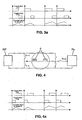
figure 3 est une vue schématique d'une machine à réluctance variable fonctionnant en élévateur de tension, - la
figure 3a illustre le diagramme de commande des interrupteurs de la machine de lafigure 3 , - la
figure 4 est une vue schématique d'une machine à réluctance variable fonctionnant en abaisseur de tension, - La
figure 4a illustre le diagramme de commande des interrupteurs de la machine de lafigure 4 , - la
figure 5 est une vue schématique d'une machine à réluctance variable fonctionnant en convertisseur de tension, - Les
figures 5a, 5b illustrent le diagramme de commande des interrupteurs de la machine de lafigure 5 , respectivement en mode recharge du réseau secondaire, et en mode décharge du réseau secondaire, - la
figure 6 est une vue schématique d'une machine à réluctance variable comportant une pluralité de bobinages inductifs reliée à un réseau secondaire d'alimentation électrique, - la
figure 7 est une vue schématique d'une machine à réluctance variable comportant une pluralité de réseaux secondaires d'alimentation électrique, - la
figure 8 est vue schématique d'un alterno-démarreur.
- the
figure 1 is a schematic view of a control half-bridge of a variable reluctance machine, - the
figure 2 is a schematic view of a control half-bridge of a variable reluctance machine according to the invention, - the
figure 3 is a schematic view of a variable reluctance machine operating as a voltage booster, - the
figure 3a illustrates the switch control chart of the machine of thefigure 3 , - the
figure 4 is a schematic view of a variable reluctance machine operating as a step-down, - The
figure 4a illustrates the switch control chart of the machine of thefigure 4 , - the
figure 5 is a schematic view of a variable reluctance machine operating as a voltage converter, - The
Figures 5a, 5b illustrate the control chart of the switches of the machine of thefigure 5 respectively in secondary network recharge mode, and in secondary network discharge mode, - the
figure 6 is a schematic view of a variable reluctance machine having a plurality of inductive coils connected to a secondary power supply network, - the
figure 7 is a schematic view of a variable reluctance machine having a plurality of secondary power supply networks, - the
figure 8 is schematic view of an alternator-starter.
Sur les différentes figures, les mêmes références désignent des éléments identiques ou similaires.In the different figures, the same references designate identical or similar elements.
Sur la
Le courant Iph sortant de ce bobinage inductif attaque, au niveau d'un point A de connexion du bobinage, le point milieu A d'un demi-pont appartenant à un variateur de commande de ladite machine, ce demi-pont étant constitué par des premier et second interrupteurs commandés T+n et T-n, montés en parallèle entre le point de connexion dudit bobinage et un réseau primaire d'alimentation électrique RP. Ce réseau d'alimentation électrique est constitué par une tension continue de type notamment 0-42V ou 0-12V.The current Iph coming out of this inductive winding drives, at a connection point A of the winding, the midpoint A of a half-bridge belonging to a control variator of said machine, this half-bridge being constituted by first and second controlled switches T + n and Tn, connected in parallel between the connection point of said winding and a primary power supply network RP. This power supply network is constituted by a DC voltage of the type in particular 0-42V or 0-12V.
Dans le cas d'une machine polyphasée, la connexion inductive entre la machine et les demi-ponts du variateur peut être réalisée soit de manière indépendante et dans ce cas aucun couplage n'est réalisé entre les phases, soit de manière dépendante, dans ce cas le couplage entre les phases et les demi-ponts est effectué à l'aide d'un montage triangle ou étoile.In the case of a polyphase machine, the inductive connection between the machine and the half-decks of the drive can be achieved either independently and in this case no coupling is performed between the phases, either in a dependent manner, in this case. case the coupling between the phases and the half-bridges is carried out using a mounting triangle or star.
La
Afin d'éviter des courts circuits entre les divers réseaux d'alimentation électrique, il est nécessaire que la commande des premier et second interrupteurs T+n, T-n soit exclusive par rapport à la commande du troisième interrupteur Tn-x, et pour se faire on introduit des temps morts dans la commande de ces interrupteurs.In order to avoid short circuits between the various power supply networks, it is necessary that the control of the first and second switches T + n, Tn be exclusive with respect to the control of the third switch Tn-x, and to be dead times are introduced into the control of these switches.
On veillera également à rendre complètement exclusive la commande des troisièmes interrupteurs Tn-x, Tn-y, Tn-z entre-eux (visibles en
La
En
Dans ce mode de fonctionnement continu, le troisième interrupteur Tn-x reste passant. La régulation de puissance transmise vers le réseau primaire d'alimentation électrique se fait par le rapport des temps de magnétisation du bobinage (conduction de T-n) et des temps de démagnétisation de ce même bobinage (conduction de T+n), comme cela est illustré en
La machine à réluctance variable représentée en
Dans ce mode de fonctionnement continu, le troisième interrupteur commandé Tn-x demeure passant et la régulation de la puissance entre le réseau primaire RP et le réseau secondaire Rx se fait par le rapport des temps de magnétisation de la self (conduction de T-n) et des temps de démagnétisation (conduction de T+n), comme cela est illustré en
La
En fonction des besoins électriques, on charge ou on décharge le réseau secondaire Rx en prélevant du courant d'au moins un bobinage. On notera que le procédé est adapté pour prélever du courant, et ce, quel que soit son sens de circulation. L'intensité de ce courant de charge ou de décharge sera adaptée en fonction du temps de conduction du troisième interrupteur Tn-x, comme cela est illustré en
La
Au niveau de sa structure, cette machine est identique à celle représentée notamment en
La
Dans cette forme de réalisation, au niveau d'un point de connexion d'un bobinage inductif n, on associe, en parallèle, une pluralité de troisièmes interrupteurs de déviation commandés T1, T2, Tx, chacun de ces interrupteurs étant relié à un réseau d'alimentation secondaire Rx, Ry, Rz.In this embodiment, at a connection point of an inductive winding n, is associated, in parallel, a plurality of third controlled deflection switches T1, T2, Tx, each of these switches being connected to a network. secondary power supply Rx, Ry, Rz.
Compte tenu, que la masse, le réseau primaire, et les réseaux secondaires sont à des potentiels électriques différents, par exemple respectivement 0, 12, 42 V, il est nécessaire que les premier, deuxième, troisième interrupteurs, respectivement T+i, T-i, Tx-i reliés à un même point de connexion d'un bobinage inductif ne soient pas commandés simultanément. (dans cet exemple, i varie de 1 à n).Given that the mass, the primary network, and the secondary networks are at different electrical potentials, for example respectively 0, 12, 42 V, it is necessary that the first, second, third, respectively T + 1, T, switch , Tx-i connected to the same connection point of an inductive winding are not controlled simultaneously. (In this example, i varies from 1 to n).
On comprend de ce qui précède que l'on peut généraliser les enseignements des formes de réalisation d'une machine à réluctance variable représentées en
Les fonctions de ce montage sont alors :
- réaliser la fonction moteur (ou démarreur) à partir de la batterie 42 V ;
- réaliser la fonction générateur sur le réseau 42 V ;
- réaliser la fonction générateur sur le réseau 12 V ;
- réaliser la fonction alimentation du réseau 12 V à partir du réseau 42 V ;
- réaliser la fonction charge de la batterie 42 V à partir de la batterie 12 V.
- perform the motor function (or starter) from the 42 V battery;
- perform the generator function on the 42 V network;
- perform the generator function on the 12 V network;
- perform the power supply function of the 12 V network from the 42 V network;
- perform the charge function of the 42 V battery from the 12 V battery.
Les deux premières fonctions sont celles demandées à un alterno-démarreur « classique » et les trois dernières sont celles demandées à un convertisseur bitension.The first two functions are those required for a "classic" alternator-starter and the last three are those requested for a dual-voltage converter.
En mode alterne-démarreur classique (42V), seuls les composants T1, D2, D3, T4 sont utilisés, ces composants sont préférentiellement des transistors pour les interrupteurs et des diodes. Dans ce cas, les bobinages de la machine sont exclusivement alimentés par le réseau principal (U1=42V). L'interrupteur T5 est ouvert et seuls T1, D2, D3 et T4 fonctionnent lorsque le courant sortant du bobinage est positif. Quand ce courant est négatif, D1, T2, T3 et D4 fonctionnent.In conventional alternator-starter mode (42V), only the components T1, D2, D3, T4 are used, these components are preferentially transistors for the switches and diodes. In this case, the windings of the machine are exclusively powered by the main network (U1 = 42V). The switch T5 is open and only T1, D2, D3 and T4 operate when the current leaving the winding is positive. When this current is negative, D1, T2, T3 and D4 work.
La combinaison des interrupteurs Tx et des diodes Dx est préférentiellement réalisée en technologie MOS.The combination of the switches Tx and diodes Dx is preferably carried out in MOS technology.
Dans ce mode de fonctionnement, il est possible d'utiliser l'interrupteur T2 lors de la conduction de D2 afin de réduire les pertes par effet Joule. L'utilisation d'un interrupteur en parallèle sur D3 peut également permettre de faire la même chose, mais dans ce cas les transistors T3, T4, T5 doivent avoir un fonctionnement exclusif (un seul passant à la fois).In this operating mode, it is possible to use the switch T2 during the conduction of D2 in order to reduce the losses by Joule effect. The use of a switch in parallel on D3 can also make it possible to do the same thing, but in this case the transistors T3, T4, T5 must have an exclusive operation (only one passer at a time).
En mode alternateur (machine tournante) ou en mode convertisseur 42V/12V (machine arrêtée), seuls les composants T1, D2, et T5 sont utilisés.In alternator mode (rotating machine) or in 42V / 12V converter mode (machine off), only T1, D2, and T5 components are used.
Un autre mode de fonctionnement peut être utilisé. Il s'agit du mode convertisseur 12V/42V ou « boost ». Dans ce cas, on utilise l'inductance de la machine. Les composants utilisés sont alors D1, T2, T5.Another mode of operation can be used. This is the 12V / 42V converter mode or "boost". In this case, the inductance of the machine is used. The components used are then D1, T2, T5.
En termes de contraintes de fonctionnement, il est important de noter que T1 et T2 ne doivent pas conduire simultanément, cela provoquerait un court circuit du réseau 42V. T5 et T4 ne doivent pas également conduire simultanément, cela provoquerait un court-circuit du réseau 12V. En fonctionnement « boost », compte tenu que le courant dans la machine est inversé et que le réseau 12 V fournit de l'énergie, il est donc nécessaire que l'interrupteur T5 soit réversible en courant.In terms of operating constraints, it is important to note that T1 and T2 should not drive simultaneously, this would cause a short circuit of the 42V network. T5 and T4 should not drive simultaneously, this would cause a short circuit of the 12V network. In "boost" operation, given that the current in the machine is reversed and that the 12 V network provides power, it is therefore necessary that the switch T5 is reversible current.
L'obtention de ces différents modes de fonctionnement est conditionnée par le pilotage adéquat des interrupteurs et la gestion optimale de leurs divers états électriques : à savoir :
- un mode ON ou passant, les premier et second interrupteurs d'un même demi-pont sont fermés et conduisent, la tension U1 ou U2 est appliquée aux bornes du bobinage n,
- un mode OFF ou ouvert, les premier et second interrupteurs sont bloqués. On applique la tension - U1 ou - U2 quand le courant est non nul aux bornes du bobinage n ou on applique une tension nulle quand le courant est nul,
- un mode « free wheel », un des interrupteurs est ouvert lorsque l'autre est passant et réciproquement, on obtient ainsi un fonctionnement en roue libre et la tension aux bornes du bobinage n est nulle,
cette gestion devant être couplée avec celle du troisième interrupteur.
- an ON or on mode, the first and second switches of the same half-bridge are closed and lead, the voltage U1 or U2 is applied across the winding n,
- an OFF or open mode, the first and second switches are blocked. The voltage - U1 or - U2 is applied when the current is non-zero across the winding n or a zero voltage is applied when the current is zero,
- a "free wheel" mode, one of the switches is open when the other is on and vice versa, thus a freewheel operation is obtained and the voltage across the winding n is zero,
this management must be coupled with that of the third switch.
La génération des commandes de l'ensemble des composants peut être réalisée soit de façon « hardware » par un circuit spécialisé du type notamment FPGA, soit de façon « software » par un microcontrôleur.The generation of the commands of all the components can be carried out either "hardware" by a specialized circuit of the type including FPGA, or "software" by a microcontroller.
Claims (6)
- Method of controlling a machine having at least one inductive coil (n), the inductive coil being connected to a primary power supply circuit (RP) via a control device comprising, between a connection point (A) of the coil (n) in question and terminals of the primary circuit (RP), at least one half-bridge of a variator suitable for controlling said machine, this half-bridge being formed by first and second controlled switches (T+n, T-n), it being possible for the first and second switches to be each in an electrical on-state or off-state, characterized in that:- the connection point (A) of said coil (n) is connected to at least a diverting third controlled switch (Tn-x) that can be in an electrical off-state or electrical on-state, this third switch (Tn-x) being connected to at least one secondary power supply circuit (Rx);- the electrical state of the third switch (Tn-x) is associated with that of the half-bridge, in such a way that the power stored in the induction coil (n) of the machine is retransmitted to the primary circuit and/or to the secondary circuit; and- the operation of the third switch (Tn-x) connected to a first secondary circuit (Rx) is carried out exclusively relative to the operation of another third switch (Tm-y) between the connection point (A) of said coil and a second secondary circuit (Ry).
- Control method according to Claim 1, in which the operation of the third switch (Tn-x) is carried out exclusively relative to the operation of the first and second switches (T+n, T-n).
- Control method according to either of the preceding claims, in which a dead time is introduced between the operations carried out on the third switches (Tn-x) so as to avoid short circuits between the primary circuit (RP) and the secondary power supply circuits (Rx).
- Use of the control method according to any one of Claims 1 to 3 for a static voltage step-up or step-down converter.
- Use of the control method according to any one of Claims 1 to 3 for a simultaneous variator and converter.
- Use of the control method according to any one of Claims 1 to 3 for a dual-voltage variable-reluctance alternator-starter.
Applications Claiming Priority (3)
| Application Number | Priority Date | Filing Date | Title |
|---|---|---|---|
| FR0110186 | 2001-07-30 | ||
| FR0110186A FR2828030B1 (en) | 2001-07-30 | 2001-07-30 | METHOD FOR CONTROLLING A VARIABLE RELUCTANCE MACHINE |
| PCT/FR2002/002565 WO2003012973A1 (en) | 2001-07-30 | 2002-07-18 | Method for controlling a variable-reluctance machine |
Publications (2)
| Publication Number | Publication Date |
|---|---|
| EP1413048A1 EP1413048A1 (en) | 2004-04-28 |
| EP1413048B1 true EP1413048B1 (en) | 2009-08-19 |
Family
ID=8866076
Family Applications (1)
| Application Number | Title | Priority Date | Filing Date |
|---|---|---|---|
| EP02767580A Expired - Fee Related EP1413048B1 (en) | 2001-07-30 | 2002-07-18 | Method for controlling a variable-reluctance machine |
Country Status (6)
| Country | Link |
|---|---|
| US (1) | US7015672B2 (en) |
| EP (1) | EP1413048B1 (en) |
| JP (1) | JP3910583B2 (en) |
| DE (1) | DE60233413D1 (en) |
| FR (1) | FR2828030B1 (en) |
| WO (1) | WO2003012973A1 (en) |
Families Citing this family (1)
| Publication number | Priority date | Publication date | Assignee | Title |
|---|---|---|---|---|
| GB0301833D0 (en) * | 2003-01-27 | 2003-02-26 | Switched Reluctance Drives Ltd | A variable reluctance generator |
Citations (1)
| Publication number | Priority date | Publication date | Assignee | Title |
|---|---|---|---|---|
| EP1039625A2 (en) * | 1999-03-23 | 2000-09-27 | Switched Reluctance Drives Limited | Operation of a switched reluctance machine from dual supply voltages |
Family Cites Families (8)
| Publication number | Priority date | Publication date | Assignee | Title |
|---|---|---|---|---|
| GB1604066A (en) * | 1978-05-26 | 1981-12-02 | Chloride Group Ltd | Battery charges in variable reluctance electric motor systems |
| US4496886A (en) * | 1982-11-08 | 1985-01-29 | Hewlett-Packard Company | Three state driver for inductive loads |
| US4698562A (en) * | 1983-10-04 | 1987-10-06 | Eaton Corporation | Motor electrical positioning system and the application thereof within vehicle traction drives |
| JPH04275096A (en) * | 1991-02-27 | 1992-09-30 | Secoh Giken Inc | Numeric controller for load |
| GB2274361B (en) * | 1993-01-13 | 1996-11-20 | Switched Reluctance Drives Ltd | Regenerative converter for a switched reluctance drive |
| DE4314290A1 (en) * | 1993-04-30 | 1994-11-03 | Manfred Dr Ing Kuchenbecker | Reluctance machine |
| GB9414116D0 (en) * | 1994-07-13 | 1994-08-31 | Switched Reluctance Drives Ltd | Polyphase switched reluctance machines |
| US6137256A (en) * | 1998-11-10 | 2000-10-24 | Tridelta Industries, Inc. | Soft turn-off controller for switched reluctance machines |
-
2001
- 2001-07-30 FR FR0110186A patent/FR2828030B1/en not_active Expired - Fee Related
-
2002
- 2002-07-18 DE DE60233413T patent/DE60233413D1/en not_active Expired - Lifetime
- 2002-07-18 EP EP02767580A patent/EP1413048B1/en not_active Expired - Fee Related
- 2002-07-18 US US10/484,678 patent/US7015672B2/en not_active Expired - Fee Related
- 2002-07-18 JP JP2003518028A patent/JP3910583B2/en not_active Expired - Fee Related
- 2002-07-18 WO PCT/FR2002/002565 patent/WO2003012973A1/en active Application Filing
Patent Citations (1)
| Publication number | Priority date | Publication date | Assignee | Title |
|---|---|---|---|---|
| EP1039625A2 (en) * | 1999-03-23 | 2000-09-27 | Switched Reluctance Drives Limited | Operation of a switched reluctance machine from dual supply voltages |
Also Published As
| Publication number | Publication date |
|---|---|
| US7015672B2 (en) | 2006-03-21 |
| FR2828030B1 (en) | 2003-12-05 |
| DE60233413D1 (en) | 2009-10-01 |
| EP1413048A1 (en) | 2004-04-28 |
| US20040239284A1 (en) | 2004-12-02 |
| FR2828030A1 (en) | 2003-01-31 |
| WO2003012973A1 (en) | 2003-02-13 |
| JP3910583B2 (en) | 2007-04-25 |
| JP2004537950A (en) | 2004-12-16 |
Similar Documents
| Publication | Publication Date | Title |
|---|---|---|
| EP0898357B1 (en) | DC energy converter device | |
| US6522105B2 (en) | Battery charging apparatus | |
| EP2258037B1 (en) | Power supply with non-isolated dc dc splitting | |
| FR2938711A1 (en) | COMBINED POWER SUPPLY AND LOAD DEVICE | |
| FR2769770A1 (en) | Device and procedure especially for controlling 3-phase generator with rectifier bridge, for motor vehicle | |
| FR2832263A1 (en) | ENERGY SOURCE UNIT | |
| JP2004519593A (en) | Energy supply device for multi-voltage power supply network of vehicle | |
| FR2738411A1 (en) | MIXED ELECTRIC POWER SUPPLY SYSTEM INVERTER AND CONTINUOUS-CONTINUOUS CONVERTER | |
| WO2013190215A1 (en) | Method for controlling the charging of a battery of an electric vehicle in a non-contact charging system | |
| EP3515749B1 (en) | Converter, controller and associated vehicle | |
| EP0147280B1 (en) | Supply method and apparatus for a load, especially a direct-current motor for bi-current railway locomotive | |
| EP1413048B1 (en) | Method for controlling a variable-reluctance machine | |
| FR2842665A1 (en) | CONTROL DEVICE FOR ON-VEHICLE GENERATOR AND ON-VEHICLE POWER SUPPLY SYSTEM USING THE SAME | |
| EP3721543A1 (en) | Dc-dc converter with pre-charging of a first electrical grid from a second electrical grid | |
| FR2738964A1 (en) | CHARGING APPARATUS | |
| JP4306946B2 (en) | Battery charger | |
| JP4306945B2 (en) | Battery charger | |
| FR3043285B1 (en) | METHOD AND DEVICE FOR CONTROLLING A ROTARY ELECTRIC MACHINE OF A MOTOR VEHICLE, AND CORRESPONDING MACHINE | |
| JP3506169B2 (en) | Power supply for internal combustion engine | |
| JP4306947B2 (en) | Battery charger | |
| FR2973601A1 (en) | Electrical circuit for use in motor vehicle, has direct current-to-direct current converter for enabling withdraw of electrical energy produced by alternator for supplying energy to one of electrical systems | |
| WO2010004190A1 (en) | Arc welding set with an optimized quasi-resonant soft-switching inverter | |
| EP3513473A1 (en) | System for transferring electrical power | |
| FR2977083A1 (en) | Power battery for use in hybrid or electric car, has set of battery cells, where each cell includes switching unit i.e. transistor, and electrical winding, where set of cells are not electrically interconnected | |
| FR2698499A1 (en) | Circuit for operating an inductive load. |
Legal Events
| Date | Code | Title | Description |
|---|---|---|---|
| PUAI | Public reference made under article 153(3) epc to a published international application that has entered the european phase |
Free format text: ORIGINAL CODE: 0009012 |
|
| 17P | Request for examination filed |
Effective date: 20040120 |
|
| AK | Designated contracting states |
Kind code of ref document: A1 Designated state(s): AT BE BG CH CY CZ DE DK EE ES FI FR GB GR IE IT LI LU MC NL PT SE SK TR |
|
| AX | Request for extension of the european patent |
Extension state: AL LT LV MK RO SI |
|
| TPAC | Observations by third parties |
Free format text: ORIGINAL CODE: EPIDOSNTIPA |
|
| RIN1 | Information on inventor provided before grant (corrected) |
Inventor name: LAURENT, JEAN-MARIE, LOUIS Inventor name: WEVERS, BRUNO Inventor name: GUILLARME, NICOLAS Inventor name: SOREL, STEPHANE, CLAUDE |
|
| RAP1 | Party data changed (applicant data changed or rights of an application transferred) |
Owner name: VALEO SYSTEMES DE CONTROLE MOTEUR |
|
| 17Q | First examination report despatched |
Effective date: 20060213 |
|
| GRAP | Despatch of communication of intention to grant a patent |
Free format text: ORIGINAL CODE: EPIDOSNIGR1 |
|
| RIC1 | Information provided on ipc code assigned before grant |
Ipc: H02P 25/08 20060101AFI20090219BHEP |
|
| GRAS | Grant fee paid |
Free format text: ORIGINAL CODE: EPIDOSNIGR3 |
|
| GRAA | (expected) grant |
Free format text: ORIGINAL CODE: 0009210 |
|
| AK | Designated contracting states |
Kind code of ref document: B1 Designated state(s): DE ES FR GB IT |
|
| REG | Reference to a national code |
Ref country code: GB Ref legal event code: FG4D Free format text: NOT ENGLISH |
|
| REF | Corresponds to: |
Ref document number: 60233413 Country of ref document: DE Date of ref document: 20091001 Kind code of ref document: P |
|
| PG25 | Lapsed in a contracting state [announced via postgrant information from national office to epo] |
Ref country code: ES Free format text: LAPSE BECAUSE OF FAILURE TO SUBMIT A TRANSLATION OF THE DESCRIPTION OR TO PAY THE FEE WITHIN THE PRESCRIBED TIME-LIMIT Effective date: 20091130 |
|
| PLBE | No opposition filed within time limit |
Free format text: ORIGINAL CODE: 0009261 |
|
| STAA | Information on the status of an ep patent application or granted ep patent |
Free format text: STATUS: NO OPPOSITION FILED WITHIN TIME LIMIT |
|
| 26N | No opposition filed |
Effective date: 20100520 |
|
| REG | Reference to a national code |
Ref country code: FR Ref legal event code: PLFP Year of fee payment: 15 |
|
| REG | Reference to a national code |
Ref country code: FR Ref legal event code: PLFP Year of fee payment: 16 |
|
| REG | Reference to a national code |
Ref country code: FR Ref legal event code: PLFP Year of fee payment: 17 |
|
| PGFP | Annual fee paid to national office [announced via postgrant information from national office to epo] |
Ref country code: IT Payment date: 20190718 Year of fee payment: 18 Ref country code: DE Payment date: 20190711 Year of fee payment: 18 Ref country code: FR Payment date: 20190731 Year of fee payment: 18 |
|
| PGFP | Annual fee paid to national office [announced via postgrant information from national office to epo] |
Ref country code: GB Payment date: 20190719 Year of fee payment: 18 |
|
| REG | Reference to a national code |
Ref country code: DE Ref legal event code: R119 Ref document number: 60233413 Country of ref document: DE |
|
| GBPC | Gb: european patent ceased through non-payment of renewal fee |
Effective date: 20200718 |
|
| PG25 | Lapsed in a contracting state [announced via postgrant information from national office to epo] |
Ref country code: GB Free format text: LAPSE BECAUSE OF NON-PAYMENT OF DUE FEES Effective date: 20200718 Ref country code: FR Free format text: LAPSE BECAUSE OF NON-PAYMENT OF DUE FEES Effective date: 20200731 |
|
| PG25 | Lapsed in a contracting state [announced via postgrant information from national office to epo] |
Ref country code: DE Free format text: LAPSE BECAUSE OF NON-PAYMENT OF DUE FEES Effective date: 20210202 |
|
| PG25 | Lapsed in a contracting state [announced via postgrant information from national office to epo] |
Ref country code: IT Free format text: LAPSE BECAUSE OF NON-PAYMENT OF DUE FEES Effective date: 20200718 |