EP1411682A1 - Modulare Ethernet-Switch Architektur mit G.Links und ohne Adressierung der Schnittstellenmodule - Google Patents
Modulare Ethernet-Switch Architektur mit G.Links und ohne Adressierung der Schnittstellenmodule Download PDFInfo
- Publication number
- EP1411682A1 EP1411682A1 EP03022768A EP03022768A EP1411682A1 EP 1411682 A1 EP1411682 A1 EP 1411682A1 EP 03022768 A EP03022768 A EP 03022768A EP 03022768 A EP03022768 A EP 03022768A EP 1411682 A1 EP1411682 A1 EP 1411682A1
- Authority
- EP
- European Patent Office
- Prior art keywords
- interface
- ports
- ethernet switch
- ethernet
- row
- Prior art date
- Legal status (The legal status is an assumption and is not a legal conclusion. Google has not performed a legal analysis and makes no representation as to the accuracy of the status listed.)
- Granted
Links
- 230000005405 multipole Effects 0.000 claims description 9
- 238000000034 method Methods 0.000 claims description 5
- 238000011144 upstream manufacturing Methods 0.000 claims description 3
- 230000005540 biological transmission Effects 0.000 description 4
- 238000006880 cross-coupling reaction Methods 0.000 description 4
- 238000012549 training Methods 0.000 description 4
- 230000008878 coupling Effects 0.000 description 3
- 238000010168 coupling process Methods 0.000 description 3
- 238000005859 coupling reaction Methods 0.000 description 3
- 239000013307 optical fiber Substances 0.000 description 3
- 238000010276 construction Methods 0.000 description 2
- 238000010586 diagram Methods 0.000 description 2
- 238000005516 engineering process Methods 0.000 description 2
- 238000012545 processing Methods 0.000 description 2
- 238000004891 communication Methods 0.000 description 1
- 230000000295 complement effect Effects 0.000 description 1
- 230000001419 dependent effect Effects 0.000 description 1
- 239000000835 fiber Substances 0.000 description 1
- 238000012423 maintenance Methods 0.000 description 1
- 230000000750 progressive effect Effects 0.000 description 1
- 230000011218 segmentation Effects 0.000 description 1
- 238000012546 transfer Methods 0.000 description 1
Images



Classifications
-
- H—ELECTRICITY
- H04—ELECTRIC COMMUNICATION TECHNIQUE
- H04L—TRANSMISSION OF DIGITAL INFORMATION, e.g. TELEGRAPHIC COMMUNICATION
- H04L49/00—Packet switching elements
- H04L49/35—Switches specially adapted for specific applications
- H04L49/351—Switches specially adapted for specific applications for local area network [LAN], e.g. Ethernet switches
-
- H—ELECTRICITY
- H04—ELECTRIC COMMUNICATION TECHNIQUE
- H04L—TRANSMISSION OF DIGITAL INFORMATION, e.g. TELEGRAPHIC COMMUNICATION
- H04L49/00—Packet switching elements
- H04L49/10—Packet switching elements characterised by the switching fabric construction
- H04L49/101—Packet switching elements characterised by the switching fabric construction using crossbar or matrix
-
- H—ELECTRICITY
- H04—ELECTRIC COMMUNICATION TECHNIQUE
- H04Q—SELECTING
- H04Q2213/00—Indexing scheme relating to selecting arrangements in general and for multiplex systems
- H04Q2213/04—Coordinate switches; Crossbar switches
Definitions
- the invention relates to an interface module for a modular Ethernet switch, such Ethernet switch and a method for modular Providing a variety of controllable Ethernet connections.
- Ethernet is therefore becoming increasingly popular Dissemination and enables cross-collaboration of the different networks, whereby things that can be transported TCP / IP a remote control, remote maintenance and / or remote sensors up to the machine tool.
- Ethernet-based Networks form switchable active distributors, in general and hereinafter referred to as the switch by segmentation of the Networks the likelihood of collisions too significantly reduce data packets transmitted.
- switch by segmentation of the Networks the likelihood of collisions too significantly reduce data packets transmitted.
- device levels are fully integrated switches with one Large number of connections, so-called multiport switches available.
- Ethernet switches therefore traditionally have one predetermined number of with a switching control unit connected ethernet interfaces and thus essentially Specified sizes to implement certain defined Functions. If the extension of the Interfaces is therefore another costly and Space-consuming, complete Ethernet switch necessary, too if it is not used in full.
- Ethernet switches are also known, in which means a cross coupling device, a so-called crossbar, a defined number of switching control units with each a specified number of Ethernet interfaces separately via a multi-pole bus line, the so-called G.Link are interconnected.
- G.Link a multi-pole bus line
- the object of the invention is to create a new and essential to show an improved way, which shown above Problems and disadvantages of the prior art in essentially excludes and in particular one user-specific or application-specific Ethernet switch provides.
- An interface module is thus according to the invention suggested using a first number of a number of ports and a second number of a series of ports, the one in the series of the first number of ports first port over a Data line with an interface device coupled switching control unit is connected and wherein the subsequent ports of the first number of the series of ports one after the other via a data line with the ports the second number of the series of ports, starting with the first port in the series the second number of ports are connected.
- a switch with a crossbar facility comprehensive head device and a number of downstream interface modules with one each first number of a number of ports and a second number a number of ports can be set up so that each match one in the series of the first number of ports an interface device, in particular one Interface device comprehensive Ethernet interfaces, coupled switching control unit is connected and the further ports of the first row of the first number of ports, in particular cascaded via respective data lines with a port of the second number of the series of ports are connected.
- each switching control unit preferably as Part of an interface module is manufactured, such that to a downstream interface module transmitting information in cascade through each upstream interface module is performed a specific addressing of the respective Interface modules are therefore no longer necessary in particular because all interface modules have the same structure and the respective addressing by connecting the is defined accordingly for individual interface modules.
- an application-specific size is due to the modular structure that meets the need efficient, space-saving and yet inexpensive Solutions, especially for the first time in the industrial sector satisfied.
- interface usage modules include in particular passive modules, for example Providing a conventional RJ-45 socket, active, for example as a transmission medium converter for coupling an optical fiber and / or for one Radio transmission trained modules and as (Intermediate) storage modules.
- the bus lines are preferred each as separate and multi-pole bus lines, so-called G. Left, trained, so that also a transfer high Amounts of data within an interface module is guaranteed.
- the crossbar facility includes in expediently also a variety of such Bus lines, which are star-shaped, each with a switching control unit are connectable.
- the head device includes further an additional interface device that by means of a bus line directly, preferably via a switching control unit the head device, with the crossbar device connected is.
- the crossbar facility in practical training a PCI (Programmable Communicaton Interface) interface for switching on one in particular Control unit for management functions, such as a CPU.
- PCI Program Programmable Communicaton Interface
- the ports By cascading through the data a respective interface module between respective Input and output ports, the ports preferably being such are trained to be both input and
- the Ethernet switch according to the invention is suitable as an output port user-specific modular construction and / or expandable.
- the high-speed bus lines, especially the crossbar device are also in preferred further training in series for easy assignment arranged.
- the invention is based on a preferred however exemplary embodiment of an inventive Ethernet switches with reference to the attached Drawing described in more detail.
- FIG. 1 through which an exemplary preferred Ethernet switch according to the invention is shown schematically.
- the Ethernet switch shown comprises a head-end station 1 and four interface modules 2a, 2b, 2c and 2d.
- each of these interface modules 2a, 2b, 2c and 2d comprises one Switching control unit 3a, 3b, 3c and 3d, each with a specified number of Ethernet-compatible interfaces 4a, 4b, 4c and 4d, in the present example with each Eight ethernet ports are comprehensively designed.
- 1 is an example of the interface device 4a of the eight Ethernet ports with the reference symbol 44a.
- Each of these ports contains the following Description provided data signals, with additional Power supplies and control signals provided become.
- the individual Ethernet ports are defined with regard to the further use and / or processing of the Signals only by switching on one application-specific interface usage module from a variety of different Interface using modules.
- the ports Specifying modules thus particularly include passive ones Modules, for example to provide a conventional one RJ-45 socket, active, for example as a transmission medium converter for coupling an optical fiber trained modules and / or as (temporary) storage trained modules.
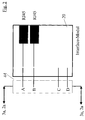
- FIG. 2 to 4 show an example of a Multifunction port 44 of the interface device 4a Fig. 1 three different, application-specific Specification of Ethernet ports 44a using specific, in 2 to 4 designated as an interface module Interface usage modules 20, the Multifunction port 44 at least one, in the present Example two Ethernet ports 44a, control signals and one Includes power supply.
- the multifunction port 44 has four in the present example Integrated, multi-core connector connections A, B, C and D on. Connections A and B are according to the following Description provided data signals of the Ethernet ports 44a on, at C the power supply and via D from a management device 8 (FIG. 1) an additional one Logic interface provided. That with Fig. 2 Interface usage module connected to multifunction port 44 20 thus puts on the connections A and B two conventional RJ-45 sockets ready. 3 with Interface usage module connected to multifunction port 44 20 also places on the connections A and B two conventional RJ-45 sockets furthermore one coupled to the connections C and D Storage.
- Port A has an RJ-45 socket and also includes one transmission medium converter coupled to connections B and C, so that in addition to the RJ-45 socket, a fiber optic socket provided for coupling an optical fiber becomes.
- each interface module 2a, 2b, 2c and 2d with a number of ports 5a, 5b, 5c serving as input ports or 5d and a number of serving as output ports Ports 6a, 6b, 6c and 6d manufactured.
- the switching control unit 3a, 3b, 3c and 3d of a respective Interface module 2a, 2b, 2c or 2d is via a Data connection to the same port of the number from input ports 5a, 5b, 5c and 5d of the respective Interface module switched on.
- the switching control unit 3a, 3b, 3c or 3d each via a separate multi-pole bus line the first input port 51a, 51b, 51c and 51d, respectively turned on.
- the subsequent ports 52, 53 and 54 of the number of Input ports 5a, 5b, 5c and 5d are with the number of Output ports 6a, 6b, 6c and 6d of the respective Interface module 2a, 2b, 2c or 2d via a predetermined cascaded arrangement connected.
- the respective one is second Positioned input port 52 with the first Output port 61, the third input port 53 with the second Output port 62 and the fourth input port 54 with the third output port 63 connected.
- the head-end station 1 further comprises a cross coupling device or a crossbar 7, which is a PCI interface to a management device 8 connectable via this, such as a CPU, includes exemplary.
- the crossbar 7 also has one Large number of multi-pole internal bus lines, the serial to at least one output port bar 9 of the head-end station 1 are switched on.
- the crossbar devices 7 of the current state of the art four to twelve internal high-speed bus lines, so-called G. Left ready.
- the input ports 5a, 5b, 5c and 5d of the Interface modules 2a, 2b, 2c and 2d are here conveniently complementary to that Output port bar 9 adapted to the head-end station.
- the head station 1 preferably further comprises at least one another own switching control unit 10, which with a according to preselected interface device 11, in In this case, in turn, an eight Ethernet ports comprehensive interface device is connected, the Specification expediently only through Connect an individual interface usage module he follows.
- the Crossbar 7 is the higher-level component that comes with each switching control unit 3a, 3b, 3c and 3d via each one of the separate multi-pole internal bus lines connected is.
- the crossbar is more conventional on the input side Way with a network component, not shown, such as for example an upstream cross coupling device connected.
- All continuing from the Crossbar 7 multipole buses or G.Link connections which is a quasi star-shaped connection between further switching and / or Control units and the Crossbar 7, are cascaded by the first interface module 2a performed, with the exception of the arranged in Fig. 1 above, on Bus input port 51a. This will be direct to the switching control unit in the interface module 2a 3a led.
- the rest of the buses carried out are arranged on the output port bar 6a such that the second bus on the input side becomes the first bus on the output side, the third bus on the input side and the second bus on the output side will etc.
- the additional module connected to the interface module 2a 2b is again via its upper one, at the input port 51b connected bus connected to the switching control unit 3a.
- first switching control unit 3a of the first interface module 2a with the crossbar 7 via the first G.Link connection B1 is connected, the second switching control unit 3b of the second Interface module 2b or the third and fourth switching control unit 3c, 3d of the following Interface module 2c, 2d on the second bus B2 of the crossbar 7 or respectively in accordance with the following third and fourth bus B3 or B4 of the crossbar 7 is connected.
- the maximum limitation of the Ethernet switch according to the invention is through the cross coupling device 7 based on the number of G.Link connections provided given, the number of input and Output port 5a-5d or 6a-6d for passing a larger one Number of bus lines compared to that in FIG. 1 number shown before four bus lines accordingly is to be adjusted.
Landscapes
- Engineering & Computer Science (AREA)
- Computer Networks & Wireless Communication (AREA)
- Signal Processing (AREA)
- Small-Scale Networks (AREA)
- Computer And Data Communications (AREA)
Abstract
Description
- Fig. 1
- eine schematische Blockdarstellung eines erfindungsgemäß modular aufgebauten Ethernet-Switches mit G.Link ohne Adressierung, und
- Fig. 2, 3 und 4
- schematische Blockdarstellungen beispielhafter Festlegungen eines Ethernet-Ports mittels unterschiedlicher Schnittstellen-Verwendungsmodule.
Claims (17)
- Schnittstellenmodul (2a, 2b, 2c, 2d) umfassend:eine erste Anzahl einer Reihe (5a, 5b, 5c, 5d) von Ports (51a, 52a, 53a, 54a, 51b, 51c, 51d) und eine zweite Anzahl einer Reihe (6a, 6b, 6c, 6d) von Ports (61a, 62a, 63a, 64a) , wobeider in der Reihe der ersten Anzahl von Ports (51a, 52a, 53a, 54a, 51b, 51c, 51d) erste Port (51a, 51b, 51c, 51d) über wenigstens eine Datenleitung mit einer, an eine Schnittstelleneinrichtung (4a, 4b, 4c, 4d) angeschaltete Schalt-Steuereinheit (3a, 3b, 3c, 3d) verbunden ist, und wobeidie nachfolgenden Eingangsports (52a, 53a, 54a) der Reihe (5a, 5b, 5c, 5d) der ersten Anzahl von Ports jeweils mittels wenigstens einer Datenleitung der Reihe nach mit den Ports (61a, 62a, 63a, 64a) der Reihe der zweiten Anzahl (6a, 6b, 6c, 6d) von Ports, beginnend mit dem ersten (61a) in der Reihe der zweiten Anzahl von Ports verbunden sind.
- Schnittstellenmodul nach Anspruch 1, wobei die Schnittstelleneinrichtung eine Anzahl von Ethernet-Schnittstellen (4a, 4b, 4c, 4d, 11) umfasst.
- Schnittstelleneinrichtung nach einem der vorstehenden Ansprüche, wobei eine Schnittstellenspezifizierung der Schnittstelleneinrichtung (4a, 4b, 4c, 4d) über wenigstens ein an die Schnittstelleneinrichtung anzuschließendes Schnittstellen-Verwendungsmodul (20) erfolgt.
- Schnittstellenmodul nach einem der vorstehenden Ansprüche, wobei Datenleitungen als separate und vielpolige Busleitungen (B1, B2, B3, B4) ausgebildet sind.
- Ethernet-Switch umfassend eine Kopfeinrichtung (1) mit einer Crossbar-Einrichtung (7) und einer Anzahl von nachgeschalteten Schnittstellenmodulen (2a, 2b, 2c, 2d), insbesondere einer Anzahl von nachgeschalteten Schnittstellenmodulen nach einem der vorstehenden Ansprüche, mit jeweils einer ersten Anzahl einer Reihe (5a, 5b, 5c, 5d) von Ports und einer zweiten Anzahl einer Reihe (6a, 6b, 6c, 6d) von Ports derart, dass jeweils der gleiche (51a, 51b, 51c, 51d) in der Reihe der ersten Anzahl (5a, 5b, 5c, 5d) von Ports mit einer an eine Schnittstelleneinrichtung (4a, 4b, 4c, 4d) gekoppelte Schalt-Steuereinheit (3a, 3b, 3c, 3d) verbunden ist und die weiteren Ports (52a, 53a, 54a) der Reihe der ersten Anzahl (5a, 5b, 5c, 5d) von Ports, jeweils über kaskadisch geführte Datenleitungen mit einem Port der zweiten Anzahl (6a, 6b, 6c, 6d) der Reihe von Ports verbunden sind.
- Ethernet-Switch nach vorstehendem Anspruch,
wobei die Crossbar-Einrichtung (7) eine Vielzahl von Busleitungen (B1, B2, B3, B4) umfasst, die sternförmig mit jeweils einer Schalt-Steuereinheit (3a, 3b, 3c, 3d) verbindbar sind. - Ethernet-Switch nach einem der vorstehenden Ansprüchen 5 oder 6, wobei die Kopfeinrichtung (1) eine Schnittstelleneinrichtung (11) umfasst, die mittels einer Busleitung direkt oder über eine Schaltsteuereinheit (9) der Kopfeinrichtung (1) mit der Crossbar-Einrichtung (7) verbunden ist.
- Ethernet-Switch nach einem der vorstehendem Ansprüche 5 bis 7, wobei die Schnittstelleneinrichtung eine Anzahl von Ethernet-Schnittstellen (4a, 4b, 4c, 4d, 11) umfasst.
- Ethernet-Switch nach einem der vorstehenden Ansprüche, 5 bis 8, umfassend wenigstens ein an wenigstens eine Schnittstelleneinrichtung (4a, 4b, 4c, 4d, 11) angeschlossenes Schnittstellen-Verwendungsmodul (20) zur Spezifizierung wenigstens einer Schnittstelle (44a).
- Ethernet-Switch nach vorstehendem Anspruch, wobei das Schnittstellen-Verwendungsmodul (20) als aktives, passives und/oder als (Zwischen-)Speichermodul ausgebildet ist.
- Ethernet-Switch nach einem der vorstehenden Ansprüche 5 bis 10, wobei die Datenleitungen (B1, B2, B3, B4) jeweils als separate, vielpolige G.Link-Verbindungen ausgebildet sind.
- Ethernet-Switch nach einem der vorstehenden Ansprüche 5 bis 11, wobei die Crossbar-Einrichtung (7) eine PCI-Schnittstelle zum Anschalten einer Managementfunktions-Einrichtung (8) umfasst.
- Ethernet-Switch nach einem der vorstehenden Ansprüche 5 bis 12, wobei der Aufbau des Ethernet-Switches modular aufgebaut und/oder erweiterbar ist.
- Ethernet-Switch nach einem der vorstehenden Ansprüche 5 bis 13, wobei die Busleitungen (B1, B2, B3, B4) seriell angeordnet sind.
- Verfahren zum Bereitstellen einer Vielzahl von schaltbaren Ethernet-Anschlüssen (4a, 4b, 4c, 4d), wobei eine Crossbar-Einrichtung (7) mit einer Vielzahl von separaten vielpoligen Datenleitungen (B1, B2, B3, B4) mit modular aneinanderreihbaren, jeweiligen Ethernet-Anschlüssen (4a, 4b, 4c, 4d) zugeordneten Schalt-Steuereinheiten (3a, 3b, 3c, 3d) über jeweils eine vordefinierte Datenleitung (B1, B2, B3, B4) verbunden wird.
- Verfahren nach Anspruch 15, bei welchem jede Schalt-Steuereinheit (3a, 3b, 3c, 3d) als Teil eines Schnittstellenmoduls (2a, 2b, 2c, 2d) hergestellt wird, derart, dass an ein nachgeschaltetes Schnittstellenmodul (2b, 2c, 2d) von der Crossbar-Einrichtung (7) zu übertragende Information kaskadenartig durch das jeweils vorangeschaltete Schnittstellenmodul (2a, 2b, 2c) durchgeführt wird.
- Verfahren nach Anspruch 15 oder 16, bei welchem die Festlegung der Vielzahl von schaltbaren Ethernet-Anschlüssen (4a, 4b, 4c, 4d) durch Anschalten von Schnittstellen-Verwendungsmodulen (20) erfolgt.
Applications Claiming Priority (2)
| Application Number | Priority Date | Filing Date | Title |
|---|---|---|---|
| DE10248140 | 2002-10-16 | ||
| DE10248140 | 2002-10-16 |
Publications (2)
| Publication Number | Publication Date |
|---|---|
| EP1411682A1 true EP1411682A1 (de) | 2004-04-21 |
| EP1411682B1 EP1411682B1 (de) | 2006-02-08 |
Family
ID=32038715
Family Applications (1)
| Application Number | Title | Priority Date | Filing Date |
|---|---|---|---|
| EP03022768A Expired - Lifetime EP1411682B1 (de) | 2002-10-16 | 2003-10-10 | Modulare Ethernet-Switch Architektur mit G.Links und ohne Adressierung der Schnittstellenmodule |
Country Status (5)
| Country | Link |
|---|---|
| US (1) | US7426205B2 (de) |
| EP (1) | EP1411682B1 (de) |
| AT (1) | ATE317612T1 (de) |
| DE (1) | DE50302370D1 (de) |
| ES (1) | ES2253624T3 (de) |
Cited By (1)
| Publication number | Priority date | Publication date | Assignee | Title |
|---|---|---|---|---|
| WO2010097347A1 (de) * | 2009-02-26 | 2010-09-02 | Robert Bosch Gmbh | Sicherheitssystem mit kontrolleinrichtung |
Families Citing this family (1)
| Publication number | Priority date | Publication date | Assignee | Title |
|---|---|---|---|---|
| DE502006004139D1 (de) * | 2006-07-20 | 2009-08-13 | Siemens Ag | Kommunikationssystem für den flexiblen Einsatz in unterschiedlichen Einsatzfällen der Automatisierungstechnik |
Citations (1)
| Publication number | Priority date | Publication date | Assignee | Title |
|---|---|---|---|---|
| WO2002041544A2 (en) * | 2000-11-17 | 2002-05-23 | Foundry Networks, Inc. | High-performance network switch |
Family Cites Families (8)
| Publication number | Priority date | Publication date | Assignee | Title |
|---|---|---|---|---|
| US5758053A (en) * | 1992-07-22 | 1998-05-26 | Hitachi, Ltd. | Fault handling and recovery for system having plural processors |
| US5493194A (en) * | 1995-02-14 | 1996-02-20 | Allen-Bradley Company, Inc. | Control signal and power bus connector arrangement for a multi-axis motor control |
| US6046999A (en) * | 1996-09-03 | 2000-04-04 | Hitachi, Ltd. | Router apparatus using ATM switch |
| US6286060B1 (en) * | 1998-06-26 | 2001-09-04 | Sun Microsystems, Inc. | Method and apparatus for providing modular I/O expansion of computing devices |
| US6690668B1 (en) * | 1998-10-19 | 2004-02-10 | Texas Instruments Incorporated | Modular interconnection of network switches |
| US6138185A (en) * | 1998-10-29 | 2000-10-24 | Mcdata Corporation | High performance crossbar switch |
| US6804193B1 (en) * | 2000-07-28 | 2004-10-12 | Marconi Intellectual Property (Ringfence) Inc. | Protected Ethernet backplane communication |
| US6590417B1 (en) * | 2001-04-03 | 2003-07-08 | Cypress Semiconductor Corporation | Cascadable bus based crossbar switch in a programmable logic device |
-
2003
- 2003-10-10 AT AT03022768T patent/ATE317612T1/de active
- 2003-10-10 DE DE50302370T patent/DE50302370D1/de not_active Expired - Lifetime
- 2003-10-10 EP EP03022768A patent/EP1411682B1/de not_active Expired - Lifetime
- 2003-10-10 ES ES03022768T patent/ES2253624T3/es not_active Expired - Lifetime
- 2003-10-16 US US10/688,025 patent/US7426205B2/en not_active Expired - Fee Related
Patent Citations (1)
| Publication number | Priority date | Publication date | Assignee | Title |
|---|---|---|---|---|
| WO2002041544A2 (en) * | 2000-11-17 | 2002-05-23 | Foundry Networks, Inc. | High-performance network switch |
Non-Patent Citations (3)
| Title |
|---|
| "10/100/1000 Ethernet: Galileo Technology Announces Availability of the first Products in The GalNet-II Architecture Family", EDGE: WORKING GROUP COMPUTING REPORT, 20 July 1998 (1998-07-20), pages 1 - 6, XP002264301, Retrieved from the Internet <URL:http://www.findarticles.com/cf_0/m0WUB/1998_July_20/50170308/p1/article.jhtml> [retrieved on 20031209] * |
| HUBBS B: "A survey of highly integrated Ethernet DataComm devices", AEROSPACE CONFERENCE, 1998 IEEE SNOWMASS AT ASPEN, CO, USA 21-28 MARCH 1998, NEW YORK, NY, USA,IEEE, US, 21 March 1998 (1998-03-21), pages 489 - 498, XP010286906, ISBN: 0-7803-4311-5 * |
| VONNAHME E ET AL: "Measurements in switched Ethernet networks used for automation systems", FACTORY COMMUNICATION SYSTEMS, 2000. PROCEEDINGS. 2000 IEEE INTERNATIONAL WORKSHOP ON PORTO, PORTUGAL 6-8 SEPT. 2000, PISCATAWAY, NJ, USA,IEEE, US, 6 September 2000 (2000-09-06), pages 231 - 238, XP010521815, ISBN: 0-7803-6500-3 * |
Cited By (1)
| Publication number | Priority date | Publication date | Assignee | Title |
|---|---|---|---|---|
| WO2010097347A1 (de) * | 2009-02-26 | 2010-09-02 | Robert Bosch Gmbh | Sicherheitssystem mit kontrolleinrichtung |
Also Published As
| Publication number | Publication date |
|---|---|
| US7426205B2 (en) | 2008-09-16 |
| DE50302370D1 (de) | 2006-04-20 |
| EP1411682B1 (de) | 2006-02-08 |
| ATE317612T1 (de) | 2006-02-15 |
| ES2253624T3 (es) | 2006-06-01 |
| US20050102417A1 (en) | 2005-05-12 |
Similar Documents
| Publication | Publication Date | Title |
|---|---|---|
| DE4404962C2 (de) | Verfahren und Anordnung zum Konfigurieren von Funktionseinheiten in einer Master-Slave-Anordnung | |
| DE69720546T2 (de) | Kaskadierter Anschluss von kommuniziernden Geräten | |
| DE2920994A1 (de) | Datensende/-empfangseinrichtung mit parallel/seriell- und seriell/parallel- zeichenumsetzung, insbesondere zum datenaustausch zwischen kommunizierenden datenverarbeitungsanlagen | |
| EP3149710B1 (de) | Fahrzeugdiagnosevorrichtung und datenübertragungsvorrichtung | |
| DE69813657T2 (de) | Architektur eines virtuellen Netzes | |
| EP0231434B1 (de) | In integrierter Technik hergestellter Baustein zur Erstellung integrierter Schaltungen | |
| EP0853366A2 (de) | Einrichtung zur Übermittlung von Steuersignalen an Ventile | |
| DE60131355T2 (de) | Paketverarbeitungsvorrichtung | |
| EP3654594A1 (de) | Verfahren zur datenübertragung, kommunikationsgerät, computerprogramm und computerlesbares medium | |
| EP1411682B1 (de) | Modulare Ethernet-Switch Architektur mit G.Links und ohne Adressierung der Schnittstellenmodule | |
| EP0792078A1 (de) | Aktuator-sensor-interface-system | |
| WO2012110541A1 (de) | Verfahren zum übertragen von daten über einen synchronen seriellen datenbus | |
| WO2005019952A1 (de) | Kopplungsvorrichtung für drei bussysteme | |
| WO2019161820A1 (de) | Integrierte kommunikationseinheit | |
| DE20217772U1 (de) | Modular aufbaubarer Ethernet-Switch mit G. Link ohne Adressierung | |
| EP2159959B1 (de) | Verfahren zur Ermittlung einer Topologie, Netzwerkkomponente und Zentraleinheit | |
| EP1607810B1 (de) | Wartungsfähige elektrische Anlage | |
| BE1031099B1 (de) | Vorrichtung mit externer, als flexibles Vernetzungssystem nutzbarer Schnittstelle | |
| DE19603296C2 (de) | Verfahren und Feldbussystem zur seriellen Datenübertragung in objektorientierten Anwendungen | |
| EP3824393B1 (de) | Schaltung zur gepufferten übertragung von daten | |
| WO2001053952A2 (de) | Multi-master-bus-system | |
| DE10355591A1 (de) | Bereitstellen von überarbeiteten Signalen an einer Mehrzahl von Toren | |
| DE102022131886A1 (de) | Vorrichtung mit externer, als flexibles Vernetzungssystem nutzbarer Schnittstelle | |
| DE602004009310T2 (de) | System und verfahren zur kommunikation über einen bus | |
| DE102011115431B4 (de) | Feldbusnetzwerkadapter und Feldbusnetzwerkteilnehmer mit Feldbusanschlüssen |
Legal Events
| Date | Code | Title | Description |
|---|---|---|---|
| PUAI | Public reference made under article 153(3) epc to a published international application that has entered the european phase |
Free format text: ORIGINAL CODE: 0009012 |
|
| AK | Designated contracting states |
Kind code of ref document: A1 Designated state(s): AT BE BG CH CY CZ DE DK EE ES FI FR GB GR HU IE IT LI LU MC NL PT RO SE SI SK TR |
|
| AX | Request for extension of the european patent |
Extension state: AL LT LV MK |
|
| 17P | Request for examination filed |
Effective date: 20040528 |
|
| 17Q | First examination report despatched |
Effective date: 20040719 |
|
| AKX | Designation fees paid |
Designated state(s): AT BE BG CH CY CZ DE DK EE ES FI FR GB GR HU IE IT LI LU MC NL PT RO SE SI SK TR |
|
| GRAP | Despatch of communication of intention to grant a patent |
Free format text: ORIGINAL CODE: EPIDOSNIGR1 |
|
| GRAS | Grant fee paid |
Free format text: ORIGINAL CODE: EPIDOSNIGR3 |
|
| GRAA | (expected) grant |
Free format text: ORIGINAL CODE: 0009210 |
|
| AK | Designated contracting states |
Kind code of ref document: B1 Designated state(s): AT BE BG CH CY CZ DE DK EE ES FI FR GB GR HU IE IT LI LU MC NL PT RO SE SI SK TR |
|
| PG25 | Lapsed in a contracting state [announced via postgrant information from national office to epo] |
Ref country code: SK Free format text: LAPSE BECAUSE OF FAILURE TO SUBMIT A TRANSLATION OF THE DESCRIPTION OR TO PAY THE FEE WITHIN THE PRESCRIBED TIME-LIMIT Effective date: 20060208 Ref country code: SI Free format text: LAPSE BECAUSE OF FAILURE TO SUBMIT A TRANSLATION OF THE DESCRIPTION OR TO PAY THE FEE WITHIN THE PRESCRIBED TIME-LIMIT Effective date: 20060208 Ref country code: IE Free format text: LAPSE BECAUSE OF FAILURE TO SUBMIT A TRANSLATION OF THE DESCRIPTION OR TO PAY THE FEE WITHIN THE PRESCRIBED TIME-LIMIT Effective date: 20060208 Ref country code: IT Free format text: LAPSE BECAUSE OF FAILURE TO SUBMIT A TRANSLATION OF THE DESCRIPTION OR TO PAY THE FEE WITHIN THE PRESCRIBED TIME-LIMIT;WARNING: LAPSES OF ITALIAN PATENTS WITH EFFECTIVE DATE BEFORE 2007 MAY HAVE OCCURRED AT ANY TIME BEFORE 2007. THE CORRECT EFFECTIVE DATE MAY BE DIFFERENT FROM THE ONE RECORDED. Effective date: 20060208 Ref country code: FI Free format text: LAPSE BECAUSE OF FAILURE TO SUBMIT A TRANSLATION OF THE DESCRIPTION OR TO PAY THE FEE WITHIN THE PRESCRIBED TIME-LIMIT Effective date: 20060208 Ref country code: RO Free format text: LAPSE BECAUSE OF FAILURE TO SUBMIT A TRANSLATION OF THE DESCRIPTION OR TO PAY THE FEE WITHIN THE PRESCRIBED TIME-LIMIT Effective date: 20060208 |
|
| REG | Reference to a national code |
Ref country code: GB Ref legal event code: FG4D Free format text: NOT ENGLISH |
|
| REG | Reference to a national code |
Ref country code: CH Ref legal event code: NV Representative=s name: BOVARD AG PATENTANWAELTE Ref country code: CH Ref legal event code: EP |
|
| GBT | Gb: translation of ep patent filed (gb section 77(6)(a)/1977) |
Effective date: 20060208 |
|
| REG | Reference to a national code |
Ref country code: IE Ref legal event code: FG4D Free format text: LANGUAGE OF EP DOCUMENT: GERMAN |
|
| REF | Corresponds to: |
Ref document number: 50302370 Country of ref document: DE Date of ref document: 20060420 Kind code of ref document: P |
|
| PG25 | Lapsed in a contracting state [announced via postgrant information from national office to epo] |
Ref country code: DK Free format text: LAPSE BECAUSE OF FAILURE TO SUBMIT A TRANSLATION OF THE DESCRIPTION OR TO PAY THE FEE WITHIN THE PRESCRIBED TIME-LIMIT Effective date: 20060508 Ref country code: BG Free format text: LAPSE BECAUSE OF FAILURE TO SUBMIT A TRANSLATION OF THE DESCRIPTION OR TO PAY THE FEE WITHIN THE PRESCRIBED TIME-LIMIT Effective date: 20060508 Ref country code: SE Free format text: LAPSE BECAUSE OF FAILURE TO SUBMIT A TRANSLATION OF THE DESCRIPTION OR TO PAY THE FEE WITHIN THE PRESCRIBED TIME-LIMIT Effective date: 20060508 |
|
| REG | Reference to a national code |
Ref country code: ES Ref legal event code: FG2A Ref document number: 2253624 Country of ref document: ES Kind code of ref document: T3 |
|
| PG25 | Lapsed in a contracting state [announced via postgrant information from national office to epo] |
Ref country code: PT Free format text: LAPSE BECAUSE OF FAILURE TO SUBMIT A TRANSLATION OF THE DESCRIPTION OR TO PAY THE FEE WITHIN THE PRESCRIBED TIME-LIMIT Effective date: 20060710 |
|
| REG | Reference to a national code |
Ref country code: IE Ref legal event code: FD4D |
|
| ET | Fr: translation filed | ||
| PG25 | Lapsed in a contracting state [announced via postgrant information from national office to epo] |
Ref country code: MC Free format text: LAPSE BECAUSE OF NON-PAYMENT OF DUE FEES Effective date: 20061031 |
|
| PLBE | No opposition filed within time limit |
Free format text: ORIGINAL CODE: 0009261 |
|
| STAA | Information on the status of an ep patent application or granted ep patent |
Free format text: STATUS: NO OPPOSITION FILED WITHIN TIME LIMIT |
|
| 26N | No opposition filed |
Effective date: 20061109 |
|
| PG25 | Lapsed in a contracting state [announced via postgrant information from national office to epo] |
Ref country code: GR Free format text: LAPSE BECAUSE OF FAILURE TO SUBMIT A TRANSLATION OF THE DESCRIPTION OR TO PAY THE FEE WITHIN THE PRESCRIBED TIME-LIMIT Effective date: 20060509 Ref country code: CZ Free format text: LAPSE BECAUSE OF FAILURE TO SUBMIT A TRANSLATION OF THE DESCRIPTION OR TO PAY THE FEE WITHIN THE PRESCRIBED TIME-LIMIT Effective date: 20060208 |
|
| PG25 | Lapsed in a contracting state [announced via postgrant information from national office to epo] |
Ref country code: EE Free format text: LAPSE BECAUSE OF FAILURE TO SUBMIT A TRANSLATION OF THE DESCRIPTION OR TO PAY THE FEE WITHIN THE PRESCRIBED TIME-LIMIT Effective date: 20060208 |
|
| PG25 | Lapsed in a contracting state [announced via postgrant information from national office to epo] |
Ref country code: HU Free format text: LAPSE BECAUSE OF FAILURE TO SUBMIT A TRANSLATION OF THE DESCRIPTION OR TO PAY THE FEE WITHIN THE PRESCRIBED TIME-LIMIT Effective date: 20060809 Ref country code: LU Free format text: LAPSE BECAUSE OF NON-PAYMENT OF DUE FEES Effective date: 20061010 Ref country code: TR Free format text: LAPSE BECAUSE OF FAILURE TO SUBMIT A TRANSLATION OF THE DESCRIPTION OR TO PAY THE FEE WITHIN THE PRESCRIBED TIME-LIMIT Effective date: 20060208 |
|
| PG25 | Lapsed in a contracting state [announced via postgrant information from national office to epo] |
Ref country code: CY Free format text: LAPSE BECAUSE OF FAILURE TO SUBMIT A TRANSLATION OF THE DESCRIPTION OR TO PAY THE FEE WITHIN THE PRESCRIBED TIME-LIMIT Effective date: 20060208 |
|
| REG | Reference to a national code |
Ref country code: CH Ref legal event code: PFA Owner name: PHOENIX CONTACT GMBH & CO. KG Free format text: PHOENIX CONTACT GMBH & CO. KG#FLACHSMARKTSTRASSE 8#32825 BLOMBERG (DE) -TRANSFER TO- PHOENIX CONTACT GMBH & CO. KG#FLACHSMARKTSTRASSE 8#32825 BLOMBERG (DE) |
|
| PGFP | Annual fee paid to national office [announced via postgrant information from national office to epo] |
Ref country code: CH Payment date: 20131024 Year of fee payment: 11 Ref country code: AT Payment date: 20131021 Year of fee payment: 11 Ref country code: GB Payment date: 20131029 Year of fee payment: 11 Ref country code: BE Payment date: 20131025 Year of fee payment: 11 Ref country code: FR Payment date: 20131028 Year of fee payment: 11 Ref country code: DE Payment date: 20131002 Year of fee payment: 11 |
|
| PGFP | Annual fee paid to national office [announced via postgrant information from national office to epo] |
Ref country code: NL Payment date: 20131028 Year of fee payment: 11 Ref country code: IT Payment date: 20131023 Year of fee payment: 11 Ref country code: ES Payment date: 20131009 Year of fee payment: 11 |
|
| REG | Reference to a national code |
Ref country code: DE Ref legal event code: R119 Ref document number: 50302370 Country of ref document: DE |
|
| REG | Reference to a national code |
Ref country code: NL Ref legal event code: V1 Effective date: 20150501 |
|
| REG | Reference to a national code |
Ref country code: CH Ref legal event code: PL |
|
| REG | Reference to a national code |
Ref country code: AT Ref legal event code: MM01 Ref document number: 317612 Country of ref document: AT Kind code of ref document: T Effective date: 20141010 |
|
| GBPC | Gb: european patent ceased through non-payment of renewal fee |
Effective date: 20141010 |
|
| PG25 | Lapsed in a contracting state [announced via postgrant information from national office to epo] |
Ref country code: BE Free format text: LAPSE BECAUSE OF NON-PAYMENT OF DUE FEES Effective date: 20141031 |
|
| PG25 | Lapsed in a contracting state [announced via postgrant information from national office to epo] |
Ref country code: DE Free format text: LAPSE BECAUSE OF NON-PAYMENT OF DUE FEES Effective date: 20150501 Ref country code: GB Free format text: LAPSE BECAUSE OF NON-PAYMENT OF DUE FEES Effective date: 20141010 Ref country code: CH Free format text: LAPSE BECAUSE OF NON-PAYMENT OF DUE FEES Effective date: 20141031 Ref country code: LI Free format text: LAPSE BECAUSE OF NON-PAYMENT OF DUE FEES Effective date: 20141031 |
|
| REG | Reference to a national code |
Ref country code: FR Ref legal event code: ST Effective date: 20150630 |
|
| PG25 | Lapsed in a contracting state [announced via postgrant information from national office to epo] |
Ref country code: FR Free format text: LAPSE BECAUSE OF NON-PAYMENT OF DUE FEES Effective date: 20141031 Ref country code: NL Free format text: LAPSE BECAUSE OF NON-PAYMENT OF DUE FEES Effective date: 20150501 Ref country code: IT Free format text: LAPSE BECAUSE OF NON-PAYMENT OF DUE FEES Effective date: 20141010 Ref country code: AT Free format text: LAPSE BECAUSE OF NON-PAYMENT OF DUE FEES Effective date: 20141010 |
|
| REG | Reference to a national code |
Ref country code: ES Ref legal event code: FD2A Effective date: 20151127 |
|
| PG25 | Lapsed in a contracting state [announced via postgrant information from national office to epo] |
Ref country code: ES Free format text: LAPSE BECAUSE OF NON-PAYMENT OF DUE FEES Effective date: 20141011 |