EP1411576A1 - Cell frame for redox flow cell and redox flow cell - Google Patents
Cell frame for redox flow cell and redox flow cell Download PDFInfo
- Publication number
- EP1411576A1 EP1411576A1 EP02724709A EP02724709A EP1411576A1 EP 1411576 A1 EP1411576 A1 EP 1411576A1 EP 02724709 A EP02724709 A EP 02724709A EP 02724709 A EP02724709 A EP 02724709A EP 1411576 A1 EP1411576 A1 EP 1411576A1
- Authority
- EP
- European Patent Office
- Prior art keywords
- frame
- cell
- redox flow
- electrolyte
- flow battery
- Prior art date
- Legal status (The legal status is an assumption and is not a legal conclusion. Google has not performed a legal analysis and makes no representation as to the accuracy of the status listed.)
- Granted
Links
Images




Classifications
-
- H—ELECTRICITY
- H01—ELECTRIC ELEMENTS
- H01M—PROCESSES OR MEANS, e.g. BATTERIES, FOR THE DIRECT CONVERSION OF CHEMICAL ENERGY INTO ELECTRICAL ENERGY
- H01M8/00—Fuel cells; Manufacture thereof
- H01M8/02—Details
- H01M8/0271—Sealing or supporting means around electrodes, matrices or membranes
- H01M8/0276—Sealing means characterised by their form
- H01M8/0278—O-rings
-
- H—ELECTRICITY
- H01—ELECTRIC ELEMENTS
- H01M—PROCESSES OR MEANS, e.g. BATTERIES, FOR THE DIRECT CONVERSION OF CHEMICAL ENERGY INTO ELECTRICAL ENERGY
- H01M8/00—Fuel cells; Manufacture thereof
- H01M8/02—Details
- H01M8/0271—Sealing or supporting means around electrodes, matrices or membranes
- H01M8/0273—Sealing or supporting means around electrodes, matrices or membranes with sealing or supporting means in the form of a frame
-
- H—ELECTRICITY
- H01—ELECTRIC ELEMENTS
- H01M—PROCESSES OR MEANS, e.g. BATTERIES, FOR THE DIRECT CONVERSION OF CHEMICAL ENERGY INTO ELECTRICAL ENERGY
- H01M8/00—Fuel cells; Manufacture thereof
- H01M8/02—Details
- H01M8/0289—Means for holding the electrolyte
-
- H—ELECTRICITY
- H01—ELECTRIC ELEMENTS
- H01M—PROCESSES OR MEANS, e.g. BATTERIES, FOR THE DIRECT CONVERSION OF CHEMICAL ENERGY INTO ELECTRICAL ENERGY
- H01M8/00—Fuel cells; Manufacture thereof
- H01M8/18—Regenerative fuel cells, e.g. redox flow batteries or secondary fuel cells
- H01M8/184—Regeneration by electrochemical means
- H01M8/188—Regeneration by electrochemical means by recharging of redox couples containing fluids; Redox flow type batteries
-
- Y—GENERAL TAGGING OF NEW TECHNOLOGICAL DEVELOPMENTS; GENERAL TAGGING OF CROSS-SECTIONAL TECHNOLOGIES SPANNING OVER SEVERAL SECTIONS OF THE IPC; TECHNICAL SUBJECTS COVERED BY FORMER USPC CROSS-REFERENCE ART COLLECTIONS [XRACs] AND DIGESTS
- Y02—TECHNOLOGIES OR APPLICATIONS FOR MITIGATION OR ADAPTATION AGAINST CLIMATE CHANGE
- Y02E—REDUCTION OF GREENHOUSE GAS [GHG] EMISSIONS, RELATED TO ENERGY GENERATION, TRANSMISSION OR DISTRIBUTION
- Y02E60/00—Enabling technologies; Technologies with a potential or indirect contribution to GHG emissions mitigation
- Y02E60/10—Energy storage using batteries
-
- Y—GENERAL TAGGING OF NEW TECHNOLOGICAL DEVELOPMENTS; GENERAL TAGGING OF CROSS-SECTIONAL TECHNOLOGIES SPANNING OVER SEVERAL SECTIONS OF THE IPC; TECHNICAL SUBJECTS COVERED BY FORMER USPC CROSS-REFERENCE ART COLLECTIONS [XRACs] AND DIGESTS
- Y02—TECHNOLOGIES OR APPLICATIONS FOR MITIGATION OR ADAPTATION AGAINST CLIMATE CHANGE
- Y02E—REDUCTION OF GREENHOUSE GAS [GHG] EMISSIONS, RELATED TO ENERGY GENERATION, TRANSMISSION OR DISTRIBUTION
- Y02E60/00—Enabling technologies; Technologies with a potential or indirect contribution to GHG emissions mitigation
- Y02E60/30—Hydrogen technology
- Y02E60/50—Fuel cells
Definitions
- the present invention relates to a cell frame for a redox flow battery designed to effectively prevent leakage of electrolyte out of the cell frame and to a redox flow battery using the same.
- the redox flow battery has a cell 1 separated into a positive electrode cell 1A and a negative electrode cell 1B by a membrane 4 that can allow ions to pass through.
- the positive electrode cell 1A and the negative electrode cell 1B include a positive electrode 5 and a negative electrode 6, respectively.
- a positive electrode tank 2 for feeding and discharging positive electrolytic solution to and from the positive electrode cell 1A is connected to the positive electrode cell 1A through conduit pipes 7, 8.
- a negative electrode tank 3 for feeding and discharging negative electrolytic solution to and from the negative electrode cell 1B is connected to the negative electrode cell 1B through conduit pipes 10, 11.
- the electrolyte containing the ions is circulated by using pumps 9, 12, to charge and discharge with the change in ionic valence at the positive electrodes 5 and negative electrodes 6.
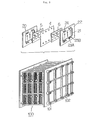
- FIG. 9 there is shown a diagrammatic illustration of construction of a cell stack used for the redox flow battery mentioned above.
- This type of battery usually uses the construction which is called a cell stack 100 comprising a plurality of cell frames 20 stacked in layers.
- the cell stack 100 comprises a stack body formed by a cell frame 20, a positive electrode 5 made of carbon felt, a membrane 4, a negative electrode 6 made of carbon felt and the cell frame 20 being repeatedly stacked in this sequence. End plates are arranged at both sides of the stack body and are clamped onto the both sides of the stack body by tightening nuts screwably engaged with long bolts 101 piercing the both end plates, to thereby produce the cell stack 100.
- the cell frame 20 comprises a bipolar plate 21 made of plastic carbon and a frame 22 formed around a periphery of the bipolar plate.
- the cell frame 22 usually has, in lower and upper sides thereof, holes which are called manifolds 23A, 23B for feeding and discharging the electrolytes to and from their respective cells and guide grooves 24 extending continuously from the manifolds for guiding the electrolyte to the electrodes 5, 6.
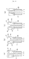
- FIG. 10 there is shown a partially enlarged view schematically showing a section around a frame when conventional cell frames are stacked in layer.
- a seal using an O-ring (FIG. 14(a)-(c)) disclosed by Japanese Laid-open (Unexamined) Patent Publication No. 2000-260460 and a seal using a flat packing (FIG. 10(d)) disclosed by Japanese Laid-open (Unexamined) Patent Publication No. Hei 8-7913 are known as a mechanism for preventing leakage of electrolyte from between the cell frames.
- Cell frames 20a shown in FIG. 10(a) each have O-ring grooves 25 formed at locations opposite to each other on both sides thereof, one for each side, and O-rings 26 are fitted in the O-ring grooves 25.
- Cell frames 20b shown in FIG. 10(b) each have an inner O-ring groove 25a formed on one side thereof and an outer O-ring groove 25b formed on the other side, both grooves being provided at locations staggered with respect to each other, and an inner O-ring 26a and an outer O-ring 26b are fitted in the grooves 25a, 25b, respectively.
- Cell frames 20c shown in FIG. 10(c) each have the inner O-ring groove 25a and the outer O-ring groove 25b, different in size from each other, which are formed on one side thereof, so that one pair of the grooves 25a, 25b is arranged in parallel with each other, and the inner O-ring 26a and the outer O-ring 26b are fitted in the grooves 25a, 25b, respectively, as is the case with the above.
- Cell frames 20d shown in FIG. 10(d) each have a flat packing 27, corresponding in shape to the cell frame 20d, which is arranged on each side.
- the present invention provides a novel cell frame for a redox flow battery comprising a bipolar plate and a frame formed around a periphery of the bipolar plate, wherein the frame has, on each side thereof, an inner seal and an outer seal to press-contact with a membrane and also seal electrolyte.
- the membrane is held in sandwich relation between the inner seals and the outer seals.
- the inner seals mainly work to prevent leakage of the electrolytes to the outside of the cell stack and mixture of the positive electrolyte and the negative electrolyte.
- the outer seals work to prevent a break in the membrane caused by dryness from propagating inwardly with respect to the outer seals, thereby preventing the leakage of the electrolytes to the outside of the cell stack.
- the membrane is held in sandwich relation between both the inner seals and the outer seals, thereby preventing the break in the membrane from progressing inwardly from a location where the membrane is sandwiched between the inner seals.
- this double seal arrangement of the present invention can ensure a high reliability with which the electrolytes are prevented from leaking out of the cell frame.
- the arrangement of the outer seals can allow slight projection of the membrane from a periphery of the cell frames. Due to this, strictness is not required for fabrication precision of the membrane and positional precision of the membrane to the cell frame, thus providing very good workability in assembling the cell stack by stacking the cell frames in layers. Further, the double seal arrangement can also serve to surely keep the membrane sandwiched between the cell frames in the wet condition.
- An O-ring is preferably used for both the inner seal and the outer seal. At least the inner seal should preferably be in the form of the O-ring, though a flat packing may be used for the outer seal.
- the cell frame may previously be provided with a groove suitable for the flat packing and an O-ring groove.
- the grooves for fitting therein the O-ring or the flat packing are provided at locations correspond to each other on both sides of the cell frame.
- the grooves may alternatively be provided at locations staggered with respect to each other on both sides of the cell frame when the cell frames having both seals are disposed opposite to each other.
- the inner seal and the outer seal are spaced apart from each other at a distance so that even when the membrane is dried and thereby broken, the break in the membrane cannot easily be propagated inwardly from the inner seal.
- the inner seal and the outer seal are spaced apart from each other at a distance of 1mm or more. The distance means a distance between center lines of the both grooves.
- the cell frame for the redox flow battery of the present invention it is preferable that the cell frame is provided with a manifold serving as a flow channel of the electrolyte and a guide groove for guiding the electrolyte from the manifold to an inside of the frame, and the guide groove has a sectional area of 5mm 2 or less.
- the sectional area defined herein is a sectional area of a single guide groove when a plurality of guide grooves are formed. As the sectional area of the guide groove increases, a quantity of electrolyte flowing through the single guide groove increases and thereby losses caused by electric current flowing in the electrolytes increase.
- the present invention specifies the sectional area of the guide groove, in order to suppress the losses caused by the electric current flowing in the electrolyte.
- a diameter of the manifold is preferably in the range of 1%-5% of a total width of the cell frame.
- a center distance between adjacent manifolds is preferably in the range of 5%-50% of a total width of the cell frame. The center distance is specified for making uniform the flow of the electrolyte in the widthwise direction in the interior of the cell frame.
- the cell frame of the present invention is preferably formed to be so transparent that one can easily inspect the each other's bonded state of the frame members and the bonded state of the frame member to the bipolar plate.
- the cell frame may be formed into shape by an injection molding using resin.
- each frame is configured so that the locations of the manifolds and the guide grooves can be symmetrical in relation to an intersection point of diagonal lines of the frame members as a center.
- the frame members symmetrical with respect to a point can all be formed into the same configuration, because they can be combined with each other by simply changing orientation. Thus, the frame members can be molded from the same mold, thus providing good productivity.
- the membrane has a thickness of 400 ⁇ m or less. This is because the membrane having a thickness of 400 ⁇ m or less is desirable in that it can provide reduced inner electrical resistance and thus improved battery efficiency.
- electric terminals for taking out electricity from the electrodes and feeding and discharging portions for feeding and discharging electrolytes to and from the electrodes are arranged on the opposite sides of the cell stack.
- This arrangement wherein the electric terminals and the feeding and discharging portions are arranged on the opposite side to each other can provide ease of maintenance as well as good workability in assembly of the battery. Further, this arrangement can provide the advantage that even when the electrolyte leaks from the supply/discharge portions, the electrical terminals are kept out of the leakage of the electrolyte, so that there is little possibility that electric current may pass through a power line.
- FIG. 1 is a plan view of a frame member forming a cell frame of the present invention.
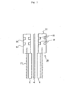
- FIG. 2 is a partially enlarged view of an area in the vicinity of the frame of the cell frames of the present invention stacked in layer.
- FIG. 3 is a partially enlarged view schematically showing a section around the frame of the cell frames of the present invention stacked in layer.
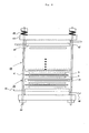
- FIG. 4 is a top view schematically showing the cell stack using the cell frames of the present invention.
- FIG. 5 is a front view of the cell stack using the cell frames of the present invention.
- FIG. 6 is a left side view of the cell stack using the cell frames of the present invention.
- FIG. 7 is a right side view of the cell stack using the cell frames of the present invention.
- FIG. 1 is a plan view of a frame member forming a cell frame of the present invention.
- FIG. 2 is a partially enlarged view of an area in the vicinity of the frame of the cell frames of the present invention stacked in layer.
- FIG. 3 is
- FIG. 8 is an explanatory view of an operating principle of the conventional redox flow battery.
- FIG. 9 is a diagrammatic illustration of construction view of the cell stack used for the redox flow battery.
- FIG. 10 is a partially enlarged view schematically showing a section around a frame of conventional cell frames when stacked in layer.
- a redox flow battery of the present invention operates in the same operation principle as that of the redox flow battery shown in FIGS. 8, 9, using a basically common overall cell stack construction. In the following, the components of the cell stack will be described in detail.
- FIG. 1 is a plan view of a frame member forming a cell frame of the present invention.
- FIG. 2 is a partially enlarged view of an area in the vicinity of the frame of the cell frames of the present invention stacked in layer.
- FIG. 3 is a partially enlarged view schematically showing a section around the same frame.
- like reference numerals denote like parts.
- Cell frames 30 of the present invention each comprises a bipolar plate 21 and a frame 31 formed around a periphery of the bipolar plate 21, as shown in FIG. 2.
- the cell frames 30 are stacked with each other, sandwiching therebetween a membrane 4 for allowing ions in electrolyte to pass through (FIG. 3).
- An inner seal 32 (FIG. 3) and an outer seal 33 (FIG. 3) for preventing leakage of electrolyte out of the frame 31 are arranged on each side of the frame 31.
- the bipolar plate 21 is disposed between a pair of frame members 31a, 31b forming the frame 31, so that an outer periphery of the bipolar plate 21 is joined to inner peripheries of the frame members 31a, 31b.
- the frame members 31a, 31b forming this cell frame 30 are formed by an injection molding or equivalent using plastics or rubbers, including vinyl chloride resin, polypropylene, polyethylene, fluorocarbon resin, and epoxy resin.
- a variety of materials may be used for the frame members 31a, 31b, as long as they have acid resistance, electrical insulating properties and mechanical strength.
- the cell frame 30 has, on each side thereof, an inner seal groove 34 for fitting therein the inner seal 32 (FIG. 3) and an outer seal groove 35 for fitting therein the outer seal 33 (FIG. 3) which are arranged to extend in parallel along a periphery of the cell frame (See FIG. 1).
- the both seal grooves 34, 35 are spaced apart from each other at a distance of not less than 1mm.
- the seal grooves 34, 35 are provided at locations correspond to each other on both sides of the cell frame 30.
- the seal grooves 34, 35 may alternatively be provided at locations staggered with respect to each other on both sides of the cell frame 30.
- the cell frames 30, each having a double seal arrangement of the seals 32, 33, can prevent the electrolyte from leaking out of the cell frames 30 when stacked in layers.
- the inner seals 32 confronting each other are brought into press-contact with both sides of the membrane 4 (FIG. 3) to sandwich the membrane 4 therebetween. This can prevent the electrolyte from leaking out of the cell frames 30 while streaming along the membrane 4 and also can prevent the positive electrolyte and the negative electrolyte from being mixed with each other.
- the outer seals 33 confronting each other are also brought into press-contact with both sides of the membrane 4 to sandwich the membrane 4 therebetween.
- Each of the cell frames 30 has a plurality of manifolds 23A, 23B formed in its long sides, as shown in FIG. 1.
- the manifolds 23A, 23B are arranged to form flow channels of the electrolytic solutions extending in a stacking direction of the cell frames when a number of cell frames are stacked in layers.
- the each cell frame has four manifolds formed on its upper side and four manifolds formed on its lower side or a total of eight manifolds.
- the manifolds arranged along the long side of the cell frame 30 are alternately used as a positive electrolyte manifold 23A and a negative electrolyte manifold 23B.
- the manifolds 23A, 23B on the lower side of the cell frame 30 are arranged in the order of the positive electrolyte feeding manifold and the negative electrolyte feeding manifold.
- the manifolds on the upper side of the cell frame 30 are arranged in the order of the positive electrolyte discharging manifold and the negative electrolyte discharging manifold. Diameters of these manifolds may be varied in consideration of the number and size of the cell frames so that pressure losses of the electrolytes passing through the manifolds can be reduced.
- a center distance between these manifolds 23A, 23B may also be varies in consideration of the number and size of the cell frames.
- O-rings (not shown) to seal the space between the cell frames are fitted in circular grooves 28 formed around the manifolds 23B.
- each cell frame 30 has, on a front side thereof, a circulation portion 24A of the electrolyte.
- the circulation portion 24A comprises electrolyte guide grooves 24A-1 extending from the manifolds 23A and rectifying portions 24A-2 for allowing the electrolyte flowing through the guide grooves 24A-1 to diffuse along an edge of the positive electrolyte 5 (FIG. 2).
- the guide grooves 24A-1 each have a rectangular section form having a round edge.
- the rectifying portions 24A-2 are formed by rectangular projections and depressions formed along the long side of the cell frame 30. The electrolyte is guided to the positive electrode 5 through the depressions.
- the number and shape of the guide groove 24A-1 and of the rectifying portion 24A-2 are not limited to those illustrated in this embodiment.
- the frame members are configured to be symmetrical with respect to a point (FIG. 1).
- the circulation portions 24A-1, 24A-2 in one long side of the frame member and the circulation portions in the other long side thereof are configured to be symmetrical in relation to an intersection point of diagonal lines of the frames as a center.
- the cell frames of the frame members being joined to each other are also configured to be symmetrical with respect to the point.
- This arrangement can provide the result that even when either of the one long side of the cell frame and the other long side of the same is put upside, the orientation of the circulation portions is kept unchanged, thus providing the advantage that the stacking work of the cell frames can be performed without paying any attention to their vertical orientations.
- the configuration that the frame members are formed to be symmetrical with respect to the point can also provide the advantage that the frame members can be molded from the same mold, thus providing good workability.
- the cell frames 30 have a thickness in the range of 2mm or more to 8mm or less, or preferably 3mm or more to 6mm or less. It is the reason for the limitation of the thickness of the cell frame to not less than 2mm that for the cell frame of less than 2mm thick, it is difficult to form the seal groove therein and also it is infeasible to apply sufficient pressure to the positive electrode 5 and the negative electrode 6 (FIG. 3) arranged between the cell frames 30, providing an increased contact resistance with the bipolar plate 21 (FIG. 3).
- the electrodes 5, 6 are also increased in thickness with the increase in thickness of the cell frame, so that pressure loss is increased for a required amount of electrolytes to pass through. That is to say, when having a thickness in the range of 2mm or more to 8mm or less, or preferably 3mm or more to 6mm or less, the cell frames 30 can provide sufficient liquid seal, providing improved battery efficiencies when used for the redox flow battery.
- the guide groove 24A-1 and the rectifying portion 24A-2 are covered with a plastic protection plate 29, when the cell frames are stacked as shown in FIG. 2.
- the protection plate 29 has a circular hole formed in a position corresponding to the manifold 23A and also has a size to cover an entire area of the guide groove 24A-1 and the rectifying portion 24A-2 and an area extended slightly upwardly from the rectifying portion 24A-2.
- the protection plate 29 serves to define a circulation passage of the electrolyte by covering upper portions of the guide groove 24A-1 and the rectifying portion 24A-2 with it.
- the protection plate 29 covering projections and depressions of the guide groove 24A-1 and rectifying portion 24A-2 serves to protect the membrane 4 from tear or damage that can be caused by the direct contact with the guide groove 24A-1 and the rectifying portion 24A-2 when the cell frames are stacked.
- the protection plate 29 is made of sufficient size to cover the area extended slightly upwardly from the rectifying portion 24A-1 as well, for the purpose of providing the function as a holder to hold upper and lower end portions of the positive electrode 5 or negative electrode between the protection plate 29 and the bipolar plate 21, to thereby produce improved workability in stacking the cell frames in layers.
- the protection plate 29 used has thickness of not more than 1mm.
- the cell frame 30 has a recessed portion 29a formed into a corresponding shape to the contour of the protection plate 29 (See FIG. 1), in order to facilitate the alignment of the protection plate 29.
- an outer edge of the bipolar plate 21 is positioned on broken lines indicated by A, B, C and both sides of the bipolar plate 21 are bonded to the back side of the each cell frame at a location thereof where the rectifying portion 24A-2 is formed.
- This arrangement can prevent the electrolyte passing through the guide groove 24A-1 and the rectifying portion 24A-2 from contacting directly with the bipolar plate 21.
- the positive electrode 5 is arranged precisely along the upper edge of the rectifying portion 24A-2.
- O-rings are used for both of the inner seal and the outer seal.
- the O-rings have a diameter of cross-section of 3mm or less.
- the inner seal 32 (FIG. 3) and the outer seal 33 (FIG. 3) may be different in diameter of cross-section from each other. Outer diameters of the O-rings may be varied properly in accordance with the size of the cell frame 30.
- the membrane 4 is formed, for example, from vinyl chloride, fluorocarbon resin, polyethylene or polypropylene.
- the membrane used has a thickness of 400 ⁇ m or less, or particularly preferably 200 ⁇ m or less, and a size slightly larger than an outer size of the frame 31 of the cell frame 30. A lower limit on the thickness of the membrane of the order of 20 ⁇ m is provided in the present circumstances.
- the bipolar plate 21 is a rectangular plate made of plastic carbon.
- the positive electrode 5 is disposed on one side of the bipolar plate and the negative electrode 6 is disposed on the other side of the bipolar plate, as shown in FIG. 3.
- This bipolar plate 21 may be formed from material comprising graphite, particles of carbon and chlorine.
- the bipolar plate used has a thickness of 0.1-1mm and a size slightly larger than a rectangular space formed around an inner periphery of the frame 31.
- the electrodes 5, 6 used are formed of carbon fibers and are formed to have a size corresponding to the rectangular space formed around the inner periphery of the frame 31.
- the frame members 31a, 31b are molded by a mold. After a pair of frame members 31a, 31b are prepared, a periphery portion of the bipolar plate 21 is adhesively bonded to inner periphery portions of the pair of frame members, to form the cell frame 30.
- the cell frames 30 are preferably formed using transparent material that one can easily inspect the each other's bonded state of the frame members 31a, 31b.
- the cell frames 30 of the present invention are stacked with the electrodes and the membranes.
- FIG. 4 is a top view schematically showing the cell stack 40 using the cell frames 30 of the present invention.
- FIG. 5 is a front view of the cell stack 40.
- FIG. 6 is a left side view of the same.
- FIG. 7 is a right side view of the same.
- like reference numerals denote like parts.
- the positive electrode 5 is arranged on one side of the bipolar plate 21 of the cell frame 30 and the negative electrode 6 is arranged on the other side of the bipolar plate 21 and, then, the electrodes are held by the protection plate 29, as shown in FIG. 2.
- the inner seal 32 (FIG. 3) and the outer seal 33 (FIG. 3) are placed in the inner seal groove 34 and the outer seal groove 35 on both sides of the cell frame 30, respectively.
- the cell stack 40 is formed in such a sequence that after the cell frames 30 comprising the bipolar plate 21, the electrodes 5, 6, the inner seal 32, and the outer seal 33 are stacked in layers to form a stacked body, the end frame 41, the plastic plate 42 made of vinyl chloride and the end plates 43 are arranged on each side of the stacked body, then tightening a number of long bolts 44 piercing from one end plate 43 to the other end plate 43.
- the end frame 41 is preferably formed by a copper plate having a plastic carbon sheet around an inside thereof. The copper plate can be surface-treated by plating, flame spray coating, vapor deposition and the like.
- the end frame 41 is provided with an electrical terminal 45 for electrical conduction.
- the plastic plate 42 is provided with a feed and discharge portion 46 for feeding and discharging the electrolyte.
- the plastic plate 42 has a thickness of 10-50mm.
- the end plate 43 has, around its margin 43a, through holes (not shown) for the long bolts 44 to be extended through and also has a latticed support 43b in a rectangular space defined in the inside of the margin 43a, as shown in FIG. 5.
- the end plate 43 with the latticed support 43b is useful for bringing all areas of the end plates to be uniformly pressed on the cell frames 30 (FIG. 4) when the end plates are clamped by tightening nuts 50 at both ends of the long bolts 44. Also, it can hold substantially the same pressing force as the conventional end plate 102 (FIG. 9) of the combination of a flat portion and a latticed portion can do.
- the rectangular space defined in the inside of the margin 43a of the end plate 43 is substantially in the form of a cavity, a least possible material is required for forming the end plate 43, thus reducing the weight of the end plate and thus reducing the burden on a worker when assembling the cell stack 40.
- coil springs 48 are disposed around end portions of the long bolts 44 to absorb thermal expansion and contraction of the cell stack.
- the long bolts 44 each have an insulating coating formed at center portions thereof. While the membrane 4 is sandwiched between the cell frames, as previously mentioned, an outer edge of the membrane 4 is sometimes exposed slightly from an outer edge of the cell frame. The membrane 4 is impregnated with electrolyte. If the long bolts 44 contact with the membrane 4 exposed from the outer edge of the cell frame, electrical conduction through the long bolts can be caused. Consequently, the long bolts 44 placed in the vicinity of the outer edge of the cell frame are also provided with the insulating coating portions so that the electrical conduction through the long bolts can be prevented.
- the end plates are isolated from the ground via an insulator support 47, in addition to the electrical isolation provided between the stacked body comprising the cell frames and the membranes and the long bolts.
- the insulating coating can be provided by painting, fitting of insulating thermal contraction tube or winding an insulating tape.
- the insulator support 47 serves as a support base of the cell stack, while ensuring the isolation between the cell stack 40 and the ground.
- electrolyte supply ports 46A, 46B and electrolyte discharge ports 46A', 46B' are arranged on an opposite surface of the cell stack 40 to a surface of the cell stack 40 on which the electrical terminals 45 are arranged, as shown in FIGS. 4, 6, 7.
- This arrangement in which the electrolyte supply ports 46A, 46B and discharge ports 46A', 46B' are arranged in the opposite direction to the electrical terminals 45 can provide ease of maintenance as well as good workability in assembly. Further, this arrangement can provide the advantage that even when the electrolyte leaks from the supply/discharge portions 46, the electrical terminals 45 are kept out of the leakage of the electrolyte, so that there is little possibility that electric current may pass through a power line.
- the electrolyte supply port 46A is for positive electrolyte and the electrolyte supply port 46B is for negative electrolyte. Also, the electrolyte discharge port 46A' is for positive electrolyte and the electrolyte discharge port 46B' is for negative electrolyte.
- a plate disposed over the cell stack 40 is a cover 49.
- a redox flow secondary battery was produced, and battery performances and discharge possible power of that redox flow secondary battery were measured. Data on material, size, and others of the cell stack and measurement results are shown below.
- Total number of cell frames 100 in total (A set of stack body with 25 cell frames stacked in layers is temporarily held, and four sets of stack bodies, each being temporarily held, are stacked in layers),
- Composition Vanadium ion concentration: 2.0 mol/L, Free sulfuric acid concentration: 2.0 mol/L, and Added phosphoric acid concentration: 0.3 mol/L, Quantity of electrolyte: 20m 3 ,
- Example 1 Using the cells of the present invention, a different redox flow secondary battery from that of Example 1 was produced, and battery performances and discharge possible power of that redox flow secondary battery was measured. Differences in data on material, size, and others of the cell stack from those of Example 1 and measurement results are shown below.
- Size Outer size 1,000mm wide, 500mm high, and 4mm thick
- Inner size 900mm wide and 300mm high
- Seal groove 2mm wide, 1mm deep, and 5mm in distance between grooves
- O-ring size 1.5mm in diameter of cross-section of the ring, and 750mm in diameter
- Inner and outer seal grooves Arranged on both sides of the cell frame at the locations shifted 8mm away from each other, Ratio of diameter of manifold to total width of cell frame: 2%, Ratio of distance between adjacent manifolds to total width of cell frame: 35%
- Material Resin comprising 90 mass% vinyl chloride and 10 mass% acrylonitrile-butadiene-styrene copolymer (ABS),
- Total number of cell frames 75 in total (A set of stack body with 25 cell frames stacked in layers is temporarily held, and three sets of stack bodies, each being temporarily held, are stacked in layers),
- Rate of spring of coil spring 1,600 (N/m), Active coils: 2.5, Contraction from free length of coil spring when clamped: 15mm,
- the cell frame for the redox flow battery and the redox flow battery using the cell frame can provide following effects.
- the double seal arrangement of the inner and outer seals can prevent the electrolyte from leaking out of the cell frames more effectively.
- the outer seal and the inner seal are spaced apart from each other at a distance so that a break in the membrane cannot be propagated inwardly, there is provided the advantage that even when a break is produced in the membrane, the electrolyte can be substantially completely prevented from leaking out of the cell frames from the break in the membrane.
- the membrane need not be fabricated with high precision or need not be located so precisely, thus providing very good workability in assembly of the battery.
- the frame members being configured to be symmetrical in relation to an intersection point of diagonal lines of the frames as a center, the frame members can be molded from the same mold, without any need to change the mold for each frame member, thus providing good productivity and economical efficiency. Further, as a result of the frame members being configured to be symmetrical with respect to a point, the cell frames joined to each other also come to be symmetrical with respect to the point. This can provide the result that when stacked, the frame members can be stacked without specifying the orientation of the frame members, thus achieving good workability in assembly.
Landscapes
- Life Sciences & Earth Sciences (AREA)
- Engineering & Computer Science (AREA)
- Manufacturing & Machinery (AREA)
- Sustainable Development (AREA)
- Sustainable Energy (AREA)
- Chemical & Material Sciences (AREA)
- Chemical Kinetics & Catalysis (AREA)
- Electrochemistry (AREA)
- General Chemical & Material Sciences (AREA)
- Fuel Cell (AREA)
- Gasket Seals (AREA)
Abstract
Description
Outer size: 1,000mm wide, 800mm high, and 5mm thick,
Inner size: 900mm wide and 600mm high,
Seal groove: 3mm wide, 1mm deep, and 5mm in distance between grooves,
O-ring size: 1.5mm in diameter of cross-section of the ring, and 1,000mm in diameter,
Inner and outer seal grooves: Arranged at the same locations on both sides of the cell frame,
Ratio of diameter of manifold to total width of cell frame: 3%,
Ratio of distance between adjacent manifolds to total width of cell frame: 30%,
Cross-sectional area of guide groove: 5mm2,
Material: Resin comprising 50 mass% vinyl chloride and 50 mass% acrylonitrile-butadiene-styrene copolymer (ABS),
Manufacturing process: Injection molding,
Material: Chlorinated polyethylene containing 10 mass% graphite,
Quantity of electrolyte: 20m3,
Rate of spring of coil spring: 1,000 (N/m),
Active coils: 3.0,
Contraction from free length of coil spring when clamped: 30mm,
Discharge possible power: 350kWH,
Others: It was found that even when the cell stack was thermally expanded and contracted during operation, no problem occurred and no leakage of electrolyte from between the cell frames occurred, either.
Outer size: 1,000mm wide, 500mm high, and 4mm thick,
Inner size: 900mm wide and 300mm high,
Seal groove: 2mm wide, 1mm deep, and 5mm in distance between grooves,
O-ring size: 1.5mm in diameter of cross-section of the ring, and 750mm in diameter,
Inner and outer seal grooves: Arranged on both sides of the cell frame at the locations shifted 8mm away from each other,
Ratio of diameter of manifold to total width of cell frame: 2%,
Ratio of distance between adjacent manifolds to total width of cell frame: 35%,
Material: Resin comprising 90 mass% vinyl chloride and 10 mass% acrylonitrile-butadiene-styrene copolymer (ABS),
Material:, Chlorinated polyethylene containing 10 mass% graphite,
Rate of spring of coil spring: 1,600 (N/m),
Active coils: 2.5,
Contraction from free length of coil spring when clamped: 15mm,
Discharge possible power: 450kWH,
Others: It was found that even when the cell stack was thermally expanded and contracted during operation, no problem occurred and no leakage of electrolyte from between the cell frames occurred, either.
Claims (9)
- A cell frame for a redox flow battery comprising a bipolar plate and a frame fitted around a periphery of the bipolar plate,
wherein the frame has, on each side thereof, an inner seal and an outer seal to press-contact with a membrane and also seal electrolyte. - The cell frame for the redox flow battery according to Claim 1, wherein the inner seal is an O-ring.
- The cell frame for the redox flow battery according to Claim 1, wherein the inner seal and the outer seal are spaced apart from each other at a distance of 1mm or more.
- The cell frame for the redox flow battery according to Claim 1, wherein the frame is provided with a manifold serving as a flow channel of the electrolyte and a guide groove for guiding the electrolyte from the manifold to an inside of the frame, and the guide groove has a sectional area of 5mm2 or less.
- The cell frame for the redox flow battery according to Claim 4, wherein a diameter of the manifold is 1%-5% of a total width of a cell frame.
- The cell frame for the redox flow battery according to Claim 4, wherein the frame is formed by bonding a pair of frame members to each other, each frame member being configured so that the guide grooves can be symmetrical in relation to an intersection point of diagonal lines of the frames as a center.
- A redox flow battery comprising a cell stack of cell frames of Claim 1, membranes and electrodes being stacked in layers.
- The redox flow battery according to Claim 7, wherein the membrane has a thickness of 400 µm or less.
- The The redox flow battery according to Claim 7, which comprises electric terminals for taking out electricity from the electrodes and feeding and discharging portions for feeding and discharging electrolytes to and from the electrodes, the electrical terminals and the feeding and discharging portions being arranged on surfaces opposite to each other.
Applications Claiming Priority (3)
| Application Number | Priority Date | Filing Date | Title |
|---|---|---|---|
| JP2001177221A JP3682244B2 (en) | 2001-06-12 | 2001-06-12 | Cell frame for redox flow battery and redox flow battery |
| JP2001177221 | 2001-06-12 | ||
| PCT/JP2002/004445 WO2002101864A1 (en) | 2001-06-12 | 2002-05-07 | Cell frame for redox flow cell and redox flow cell |
Publications (3)
| Publication Number | Publication Date |
|---|---|
| EP1411576A1 true EP1411576A1 (en) | 2004-04-21 |
| EP1411576A4 EP1411576A4 (en) | 2009-09-23 |
| EP1411576B1 EP1411576B1 (en) | 2011-10-12 |
Family
ID=19018094
Family Applications (1)
| Application Number | Title | Priority Date | Filing Date |
|---|---|---|---|
| EP02724709A Expired - Lifetime EP1411576B1 (en) | 2001-06-12 | 2002-05-07 | Cell frame for redox flow battery, and redox flow battery |
Country Status (7)
| Country | Link |
|---|---|
| US (2) | US20040170893A1 (en) |
| EP (1) | EP1411576B1 (en) |
| JP (1) | JP3682244B2 (en) |
| CN (1) | CN1531761A (en) |
| CA (1) | CA2450517C (en) |
| TW (1) | TW541737B (en) |
| WO (1) | WO2002101864A1 (en) |
Cited By (24)
| Publication number | Priority date | Publication date | Assignee | Title |
|---|---|---|---|---|
| AT510250A1 (en) * | 2010-07-21 | 2012-02-15 | Cellstrom Gmbh | FRAME OF A CELL OF A REDOX FLOW BATTERY |
| CN102760903A (en) * | 2012-08-07 | 2012-10-31 | 中国东方电气集团有限公司 | Vanadium battery |
| US8691413B2 (en) | 2012-07-27 | 2014-04-08 | Sun Catalytix Corporation | Aqueous redox flow batteries featuring improved cell design characteristics |
| US8753761B2 (en) | 2012-07-27 | 2014-06-17 | Sun Catalytix Corporation | Aqueous redox flow batteries comprising metal ligand coordination compounds |
| US9692077B2 (en) | 2012-07-27 | 2017-06-27 | Lockheed Martin Advanced Energy Storage, Llc | Aqueous redox flow batteries comprising matched ionomer membranes |
| US9768463B2 (en) | 2012-07-27 | 2017-09-19 | Lockheed Martin Advanced Energy Storage, Llc | Aqueous redox flow batteries comprising metal ligand coordination compounds |
| US9837679B2 (en) | 2014-11-26 | 2017-12-05 | Lockheed Martin Advanced Energy Storage, Llc | Metal complexes of substituted catecholates and redox flow batteries containing the same |
| US9865893B2 (en) | 2012-07-27 | 2018-01-09 | Lockheed Martin Advanced Energy Storage, Llc | Electrochemical energy storage systems and methods featuring optimal membrane systems |
| CN107710487A (en) * | 2015-06-23 | 2018-02-16 | 住友电气工业株式会社 | Bipolar plates, battery frame, battery pile and redox flow batteries |
| US9899694B2 (en) | 2012-07-27 | 2018-02-20 | Lockheed Martin Advanced Energy Storage, Llc | Electrochemical energy storage systems and methods featuring high open circuit potential |
| US9938308B2 (en) | 2016-04-07 | 2018-04-10 | Lockheed Martin Energy, Llc | Coordination compounds having redox non-innocent ligands and flow batteries containing the same |
| US9991543B2 (en) | 2012-07-27 | 2018-06-05 | Lockheed Martin Advanced Energy Storage, Llc | Aqueous redox flow batteries featuring improved cell design characteristics |
| US10065977B2 (en) | 2016-10-19 | 2018-09-04 | Lockheed Martin Advanced Energy Storage, Llc | Concerted processes for forming 1,2,4-trihydroxybenzene from hydroquinone |
| US10164284B2 (en) | 2012-07-27 | 2018-12-25 | Lockheed Martin Energy, Llc | Aqueous redox flow batteries featuring improved cell design characteristics |
| US10253051B2 (en) | 2015-03-16 | 2019-04-09 | Lockheed Martin Energy, Llc | Preparation of titanium catecholate complexes in aqueous solution using titanium tetrachloride or titanium oxychloride |
| US10320023B2 (en) | 2017-02-16 | 2019-06-11 | Lockheed Martin Energy, Llc | Neat methods for forming titanium catecholate complexes and associated compositions |
| US10316047B2 (en) | 2016-03-03 | 2019-06-11 | Lockheed Martin Energy, Llc | Processes for forming coordination complexes containing monosulfonated catecholate ligands |
| US10343964B2 (en) | 2016-07-26 | 2019-07-09 | Lockheed Martin Energy, Llc | Processes for forming titanium catechol complexes |
| US10377687B2 (en) | 2016-07-26 | 2019-08-13 | Lockheed Martin Energy, Llc | Processes for forming titanium catechol complexes |
| US10483581B2 (en) | 2012-07-27 | 2019-11-19 | Lockheed Martin Energy, Llc | Electrochemical energy storage systems and methods featuring large negative half-cell potentials |
| US10497958B2 (en) | 2016-12-14 | 2019-12-03 | Lockheed Martin Energy, Llc | Coordinatively unsaturated titanium catecholate complexes and processes associated therewith |
| US10644342B2 (en) | 2016-03-03 | 2020-05-05 | Lockheed Martin Energy, Llc | Coordination complexes containing monosulfonated catecholate ligands and methods for producing the same |
| US10741864B2 (en) | 2016-12-30 | 2020-08-11 | Lockheed Martin Energy, Llc | Aqueous methods for forming titanium catecholate complexes and associated compositions |
| US10930937B2 (en) | 2016-11-23 | 2021-02-23 | Lockheed Martin Energy, Llc | Flow batteries incorporating active materials containing doubly bridged aromatic groups |
Families Citing this family (116)
| Publication number | Priority date | Publication date | Assignee | Title |
|---|---|---|---|---|
| US8277964B2 (en) | 2004-01-15 | 2012-10-02 | Jd Holding Inc. | System and method for optimizing efficiency and power output from a vanadium redox battery energy storage system |
| US8722235B2 (en) | 2004-04-21 | 2014-05-13 | Blue Spark Technologies, Inc. | Thin printable flexible electrochemical cell and method of making the same |
| US8029927B2 (en) | 2005-03-22 | 2011-10-04 | Blue Spark Technologies, Inc. | Thin printable electrochemical cell utilizing a “picture frame” and methods of making the same |
| US8722233B2 (en) | 2005-05-06 | 2014-05-13 | Blue Spark Technologies, Inc. | RFID antenna-battery assembly and the method to make the same |
| KR100980104B1 (en) * | 2005-09-28 | 2010-09-07 | 주식회사 엘지화학 | Secondary Battery Manufacturing Equipment |
| US8197979B2 (en) * | 2006-12-12 | 2012-06-12 | Corning Incorporated | Thermo-mechanical robust seal structure for solid oxide fuel cells |
| US7855005B2 (en) * | 2007-02-12 | 2010-12-21 | Deeya Energy, Inc. | Apparatus and methods of determination of state of charge in a redox flow battery |
| US8587150B2 (en) * | 2008-02-28 | 2013-11-19 | Deeya Energy, Inc. | Method and modular system for charging a battery |
| CN101587959B (en) * | 2008-05-23 | 2012-05-16 | 大连融科储能技术发展有限公司 | An electrode frame and an all-vanadium liquid flow energy storage battery stack |
| US7927731B2 (en) * | 2008-07-01 | 2011-04-19 | Deeya Energy, Inc. | Redox flow cell |
| US7820321B2 (en) | 2008-07-07 | 2010-10-26 | Enervault Corporation | Redox flow battery system for distributed energy storage |
| US8785023B2 (en) | 2008-07-07 | 2014-07-22 | Enervault Corparation | Cascade redox flow battery systems |
| CN102246338B (en) * | 2008-10-10 | 2014-06-11 | 迪亚能源股份有限公司 | Thermal control of a flow cell battery |
| US8230736B2 (en) * | 2008-10-10 | 2012-07-31 | Deeya Energy, Inc. | Level sensor for conductive liquids |
| US8231993B2 (en) * | 2008-10-10 | 2012-07-31 | Deeya Energy, Inc. | Flexible multi-walled tubing assembly |
| EP2351184A4 (en) * | 2008-10-10 | 2014-07-09 | Deeya Energy Technologies Inc | Method and apparatus for determining state of charge of a battery |
| WO2010042900A1 (en) * | 2008-10-10 | 2010-04-15 | Deeya Energy Technologies, Inc. | Methods for bonding porous flexible membranes using solvent |
| US8236463B2 (en) * | 2008-10-10 | 2012-08-07 | Deeya Energy, Inc. | Magnetic current collector |
| US20100136455A1 (en) * | 2008-10-10 | 2010-06-03 | Rick Winter | Common Module Stack Component Design |
| US20100092843A1 (en) * | 2008-10-10 | 2010-04-15 | Deeya Energy Technologies, Inc. | Venturi pumping system in a hydrogen gas circulation of a flow battery |
| CN102460811B (en) * | 2009-05-28 | 2015-11-25 | 艾默吉电力系统股份有限公司 | Redox flow cell rebalancing |
| EP2436080A2 (en) * | 2009-05-28 | 2012-04-04 | Deeya Energy, Inc. | Electrolyte compositions |
| CN102460812B (en) * | 2009-05-28 | 2014-12-31 | 艾默吉电力系统股份有限公司 | Preparation of flow battery electrolytes from raw materials |
| US8349477B2 (en) * | 2009-05-28 | 2013-01-08 | Deeya Energy, Inc. | Optical leak detection sensor |
| US8587255B2 (en) * | 2009-05-28 | 2013-11-19 | Deeya Energy, Inc. | Control system for a flow cell battery |
| US8723489B2 (en) * | 2009-05-28 | 2014-05-13 | Deeya Energy, Inc. | Bi-directional buck-boost circuit |
| US8551299B2 (en) * | 2009-05-29 | 2013-10-08 | Deeya Energy, Inc. | Methods of producing hydrochloric acid from hydrogen gas and chlorine gas |
| CN101651220B (en) * | 2009-07-15 | 2011-11-09 | 中南大学 | High-tightness flow battery |
| US8951665B2 (en) * | 2010-03-10 | 2015-02-10 | Imergy Power Systems, Inc. | Methods for the preparation of electrolytes for chromium-iron redox flow batteries |
| US9281535B2 (en) | 2010-08-12 | 2016-03-08 | Imergy Power Systems, Inc. | System dongle |
| US8709629B2 (en) | 2010-12-22 | 2014-04-29 | Jd Holding Inc. | Systems and methods for redox flow battery scalable modular reactant storage |
| CN103339762B (en) | 2011-01-13 | 2016-03-30 | 伊莫基动力系统公司 | Flow cell stack |
| US8916281B2 (en) | 2011-03-29 | 2014-12-23 | Enervault Corporation | Rebalancing electrolytes in redox flow battery systems |
| US8980484B2 (en) | 2011-03-29 | 2015-03-17 | Enervault Corporation | Monitoring electrolyte concentrations in redox flow battery systems |
| JP5427263B2 (en) | 2011-03-31 | 2014-02-26 | 日本バルカー工業株式会社 | Seal material for thin plate members |
| JP5477672B2 (en) * | 2011-03-31 | 2014-04-23 | 住友電気工業株式会社 | Cell frame for electrolyte flow type battery, cell stack for electrolyte flow type battery, and electrolyte flow type battery |
| CN102244212B (en) * | 2011-05-25 | 2013-09-11 | 深圳市金钒能源科技有限公司 | Sealing method for galvanic pile of vanadium liquid flow battery and galvanic pile unit and galvanic pile of vanadium liquid flow battery |
| US20130029196A1 (en) * | 2011-07-29 | 2013-01-31 | Pratt & Whitney Rocketdyne, Inc. | Flow battery cells arranged between an inlet manifold and an outlet manifold |
| CN108075145B (en) * | 2011-08-22 | 2022-01-07 | 安辛可公司 | Reversible polarity operation and switching method for ZnBr flow cell connected to common DC bus |
| US9577242B2 (en) * | 2011-08-22 | 2017-02-21 | Ensync, Inc. | Internal header flow divider for uniform electrolyte distribution |
| US9774044B2 (en) | 2011-09-21 | 2017-09-26 | United Technologies Corporation | Flow battery stack with an integrated heat exchanger |
| WO2013044224A2 (en) | 2011-09-22 | 2013-03-28 | Blue Spark Technologies, Inc. | Cell attachment method |
| US10141594B2 (en) * | 2011-10-07 | 2018-11-27 | Vrb Energy Inc. | Systems and methods for assembling redox flow battery reactor cells |
| CN102420335B (en) * | 2011-10-25 | 2013-12-18 | 中国科学院长春应用化学研究所 | Assembling method of self-breathing type direct alcohol fuel cell |
| JP6016197B2 (en) * | 2011-11-22 | 2016-10-26 | 住友電気工業株式会社 | Membrane for redox flow battery |
| US9853454B2 (en) | 2011-12-20 | 2017-12-26 | Jd Holding Inc. | Vanadium redox battery energy storage system |
| DE102011122010A1 (en) | 2011-12-23 | 2013-06-27 | Fraunhofer-Gesellschaft zur Förderung der angewandten Forschung e.V. | Redox flow battery with external supply line and / or disposal line |
| CN102593495B (en) * | 2012-03-05 | 2014-10-22 | 上海裕豪机电有限公司 | Oxidation reduction flow cell |
| DE102012006642A1 (en) * | 2012-04-03 | 2013-10-10 | Bozankaya BC&C | Flow battery, electrochemical energy converter for a flow battery, cell frame and bipolar plate and collector plate |
| US8765284B2 (en) | 2012-05-21 | 2014-07-01 | Blue Spark Technologies, Inc. | Multi-cell battery |
| WO2014070254A1 (en) | 2012-11-01 | 2014-05-08 | Blue Spark Technologies, Inc. | Body temperature logging patch |
| WO2014085604A1 (en) | 2012-11-27 | 2014-06-05 | Blue Spark Technologies, Inc. | Battery cell construction |
| USD756912S1 (en) * | 2013-02-04 | 2016-05-24 | Sumitomo Electric Industries, Ltd. | Redox flow battery cell stack |
| AU2014223472B2 (en) * | 2013-02-28 | 2018-03-08 | Nuvera Fuel Cells, LLC | Electrochemical cell having a cascade seal configuration and hydrogen reclamation |
| AT513834B1 (en) * | 2013-03-01 | 2014-08-15 | Cellstrom Gmbh | Elastomer end frame of a redox flow battery |
| WO2014162326A1 (en) | 2013-03-30 | 2014-10-09 | Leシステム株式会社 | Redox flow battery and method for operating same |
| DE102013009629B4 (en) * | 2013-06-10 | 2019-09-12 | Carl Freudenberg Kg | Electrode module and arrangement with electrode modules |
| EP2824748B1 (en) | 2013-07-12 | 2016-10-12 | OCI Company Ltd. | Cell frame for improved flow distributing and redox flow battery having the same |
| KR101586117B1 (en) * | 2013-07-12 | 2016-01-15 | 오씨아이 주식회사 | Redox flow battery and cell frame |
| KR101459927B1 (en) * | 2013-07-12 | 2014-11-07 | 오씨아이 주식회사 | Cell frmae for improved flow distributing and redox flow battery having the same |
| DE102013107516A1 (en) | 2013-07-16 | 2015-01-22 | Fraunhofer-Gesellschaft zur Förderung der angewandten Forschung e.V. | Cell and cell stack of a redox flow battery |
| CN103367776B (en) * | 2013-07-23 | 2017-07-14 | 大连融科储能技术发展有限公司 | Diaphragm, electric stack and electric stack sealing method of a liquid flow battery |
| CA2919369A1 (en) | 2013-07-29 | 2015-02-05 | Nuvera Fuel Cells, Inc. | Seal configuration for electrochemical cell |
| AU2014336948B2 (en) * | 2013-10-15 | 2018-04-12 | Redflow R&D Pty Ltd | Electrode plate and methods for manufacturing and testing an electrode plate |
| JP6150069B2 (en) * | 2013-10-23 | 2017-06-21 | 住友電気工業株式会社 | Electrolyte circulation battery and electrolyte circulation battery supply / discharge plate |
| US20150125768A1 (en) * | 2013-11-07 | 2015-05-07 | Enervault Corporation | Cell and Cell Block Configurations for Redox Flow Battery Systems |
| JP6103386B2 (en) | 2014-01-24 | 2017-03-29 | 住友電気工業株式会社 | Redox flow battery |
| US10079401B2 (en) | 2014-03-24 | 2018-09-18 | Cornell University | Symmetric redox flow battery containing organic redox active molecule |
| WO2015148358A1 (en) | 2014-03-24 | 2015-10-01 | Cornell University | Solar flow battery |
| JP6201876B2 (en) | 2014-04-23 | 2017-09-27 | 住友電気工業株式会社 | Bipolar plate, redox flow battery, and bipolar plate manufacturing method |
| JP6247590B2 (en) * | 2014-05-07 | 2017-12-13 | 旭化成株式会社 | Cell stack and storage battery |
| WO2016033147A1 (en) | 2014-08-28 | 2016-03-03 | Nuvera Fuel Cells, Inc. | Seal designs for multicomponent bipolar plates of an electrochemical cell |
| JP6380911B2 (en) * | 2014-11-05 | 2018-08-29 | 住友電気工業株式会社 | Electrolyte circulating battery |
| KR101689134B1 (en) * | 2014-11-17 | 2016-12-27 | 한국에너지기술연구원 | Redox Flow Battery |
| KR101761460B1 (en) * | 2014-12-17 | 2017-07-26 | 오씨아이 주식회사 | Cell stack of redox flow battery |
| US9693689B2 (en) | 2014-12-31 | 2017-07-04 | Blue Spark Technologies, Inc. | Body temperature logging patch |
| KR101560202B1 (en) * | 2015-04-30 | 2015-10-14 | 스탠다드에너지(주) | Redox flow battery |
| TWI575805B (en) * | 2015-10-15 | 2017-03-21 | 行政院原子能委員會核能研究所 | Bipolar Plate of Flow Cell and Producing Method Thereof |
| KR101754505B1 (en) * | 2015-12-24 | 2017-07-06 | 오씨아이 주식회사 | Cell stack of redox flow battery |
| JP6540961B2 (en) * | 2016-01-26 | 2019-07-10 | 住友電気工業株式会社 | Battery and seal material |
| AU2016391240B2 (en) * | 2016-02-03 | 2021-10-21 | Sumitomo Electric Industries, Ltd. | Redox flow battery |
| JP2017157340A (en) * | 2016-02-29 | 2017-09-07 | 住友電気工業株式会社 | Redox flow cell |
| JP6677045B2 (en) | 2016-03-29 | 2020-04-08 | 住友電気工業株式会社 | Frame for redox flow battery, redox flow battery, and cell stack |
| DE102016004027A1 (en) | 2016-04-04 | 2017-10-05 | VoltStorage GmbH | Cell and cell stack of a redox flow battery and method of making this cell stack |
| KR101742980B1 (en) * | 2016-04-15 | 2017-06-05 | 스탠다드에너지(주) | Redox flow battery for reducing shunt current |
| JPWO2017183643A1 (en) * | 2016-04-20 | 2019-02-28 | 住友電気工業株式会社 | Redox flow battery transport structure, redox flow battery transport method, and redox flow battery |
| KR102365550B1 (en) * | 2016-11-09 | 2022-02-23 | 다롄 룽커파워 씨오., 엘티디 | Electrode structure of flow battery, flow battery stack, and sealing structure for flow battery stack |
| KR20190077241A (en) * | 2016-11-16 | 2019-07-03 | 스미토모덴키고교가부시키가이샤 | Cell frame, cell stack, and redox flow cell |
| AU2016429827A1 (en) * | 2016-11-16 | 2018-06-28 | Sumitomo Electric Industries, Ltd. | Cell frame, cell stack, and redox flow battery |
| JP6873424B2 (en) * | 2017-01-11 | 2021-05-19 | 日本圧着端子製造株式会社 | Board-to-board connector |
| WO2018134955A1 (en) * | 2017-01-19 | 2018-07-26 | 住友電気工業株式会社 | Bipolar plate, cell frame, cell stack and redox flow battery |
| US20180331383A1 (en) * | 2017-05-09 | 2018-11-15 | Jinfeng Wu | Gasket assemblies for redox flow batteries |
| US20210143450A1 (en) * | 2017-06-13 | 2021-05-13 | Itn Energy Systems, Inc. | Floating frame plate assembly |
| WO2019030817A1 (en) * | 2017-08-08 | 2019-02-14 | 住友電気工業株式会社 | Redox flow battery and method for operating redox flow battery |
| US10849501B2 (en) | 2017-08-09 | 2020-12-01 | Blue Spark Technologies, Inc. | Body temperature logging patch |
| WO2019030903A1 (en) * | 2017-08-10 | 2019-02-14 | 住友電気工業株式会社 | Cell stack and redox flow battery |
| WO2019046724A1 (en) | 2017-09-01 | 2019-03-07 | Itn Energy Systems, Inc. | Segmented frames for redox flow batteries |
| WO2019049333A1 (en) * | 2017-09-08 | 2019-03-14 | 住友電気工業株式会社 | Redox flow battery cell, redox flow battery cell stack, and redox flow battery |
| JP6991468B2 (en) * | 2018-02-27 | 2022-01-12 | 住友電気工業株式会社 | Cell stack and redox flow battery |
| WO2019167144A1 (en) * | 2018-02-27 | 2019-09-06 | 住友電気工業株式会社 | Cell stack and redox flow battery |
| CN110416584B (en) * | 2018-04-27 | 2021-04-16 | 江苏泛宇能源有限公司 | Stack Frames for Flow Batteries |
| DE102019101474A1 (en) | 2019-01-22 | 2020-07-23 | Volterion GmbH | Distribution module for connecting cells of a cell stack and cell stack with a distribution module |
| DE102019103542A1 (en) | 2019-02-13 | 2020-08-13 | Fraunhofer-Gesellschaft zur Förderung der angewandten Forschung e.V. | Process for hydrophilizing a semi-finished element and the electrode element, bipolar element or heat exchanger element produced thereby |
| CN113823806B (en) * | 2020-06-19 | 2023-02-03 | 中国科学院大连化学物理研究所 | Integrated electrode frame structure for all-vanadium redox flow battery, preparation method and application |
| DE102020117367B4 (en) | 2020-07-01 | 2022-04-21 | Fraunhofer-Gesellschaft zur Förderung der angewandten Forschung eingetragener Verein | Cell frame, electrochemical cell, cell stack and method of operation |
| CN111883798B (en) * | 2020-07-24 | 2021-11-16 | 苏州敦胜新能源科技有限公司 | A high temperature fuel cell integrated bipolar plate |
| DE102020122478B4 (en) | 2020-08-27 | 2023-07-20 | FB-TEST-DEV GmbH | Cell stack including a cell and method of making a cell stack |
| DE102020124801A1 (en) | 2020-09-23 | 2022-03-24 | Fraunhofer-Gesellschaft zur Förderung der angewandten Forschung eingetragener Verein | Electrochemical cell, in particular a redox flow battery, and corresponding cell stack |
| DE102021111054B3 (en) * | 2021-04-29 | 2022-05-12 | Schaeffler Technologies AG & Co. KG | Redox flow cell and method for its assembly and redox flow battery |
| EP4360148A1 (en) | 2021-06-22 | 2024-05-01 | Fraunhofer-Gesellschaft zur Förderung der angewandten Forschung e.V. | Structure-integrated electrochemical cell and structure-integrated stack constructed therefrom |
| CN113540495B (en) * | 2021-07-09 | 2022-09-20 | 刘学军 | Flow frame structure of flow battery and side surface packaging method thereof |
| CN114039076A (en) | 2021-11-02 | 2022-02-11 | 北京普能世纪科技有限公司 | Distributed large-scale system of all-vanadium redox flow battery |
| DE102023100399B4 (en) | 2023-01-10 | 2024-10-10 | Fraunhofer-Gesellschaft zur Förderung der angewandten Forschung eingetragener Verein | CELL FRAME, ELECTROCHEMICAL CELL AND ELECTROCHEMICAL FLOW REACTOR |
| EP4401173A1 (en) | 2023-01-16 | 2024-07-17 | Liva Power Management Systems GmbH | Stack rack system |
| KR102897958B1 (en) * | 2023-08-22 | 2025-12-09 | 주식회사 에이치투 | Redox Flow Battery With Fiber Reniforced Plastic Endplate Having Grating Structure |
| WO2025184823A1 (en) * | 2024-03-06 | 2025-09-12 | Mann+Hummel Life Sciences & Environment Holding Singapore Pte. Ltd. | Electrochemical stack, redox flow battery, and method of producing electricity |
Family Cites Families (10)
| Publication number | Priority date | Publication date | Assignee | Title |
|---|---|---|---|---|
| DK171869B1 (en) | 1985-10-22 | 1997-07-21 | Takeda Chemical Industries Ltd | Process for preparing 2-keto-L-gulonic acid and biologically pure microorganism culture for use in the process |
| JPH0821400B2 (en) * | 1987-03-04 | 1996-03-04 | 関西電力株式会社 | Electrolyte circulation type secondary battery |
| JP2842600B2 (en) | 1989-01-10 | 1999-01-06 | 関西電力 株式会社 | Cell stack for electrolyte circulating type secondary battery and cell stack mounting member |
| JPH0515320A (en) | 1991-07-11 | 1993-01-26 | San Ei Chem Ind Ltd | Method for coloring jellies into red color |
| JPH0515320U (en) | 1991-07-31 | 1993-02-26 | 住友電気工業株式会社 | Stacked secondary battery |
| JP2606335Y2 (en) * | 1992-06-29 | 2000-10-23 | 住友電気工業株式会社 | Redox flow battery cell |
| JPH087913A (en) | 1994-06-22 | 1996-01-12 | Kashima Kita Kyodo Hatsuden Kk | Full vanadium redox cell |
| JP3143613B2 (en) | 1999-03-05 | 2001-03-07 | 住友電気工業株式会社 | Cell for redox flow type secondary battery |
| DE69905177T2 (en) * | 1999-07-01 | 2003-06-05 | Squirrel Holdings Ltd., George Town | BIPOLAR MULTI-CELL ELECTROCHEMICAL REACTOR ISOLATED BY MEMBRANE |
| JP2001155758A (en) * | 1999-11-25 | 2001-06-08 | Sumitomo Electric Ind Ltd | Cell stack of redox flow secondary battery |
-
2001
- 2001-06-12 JP JP2001177221A patent/JP3682244B2/en not_active Expired - Fee Related
-
2002
- 2002-04-10 TW TW091107172A patent/TW541737B/en not_active IP Right Cessation
- 2002-05-07 WO PCT/JP2002/004445 patent/WO2002101864A1/en not_active Ceased
- 2002-05-07 CA CA002450517A patent/CA2450517C/en not_active Expired - Lifetime
- 2002-05-07 US US10/480,117 patent/US20040170893A1/en not_active Abandoned
- 2002-05-07 CN CNA028116275A patent/CN1531761A/en active Pending
- 2002-05-07 EP EP02724709A patent/EP1411576B1/en not_active Expired - Lifetime
-
2007
- 2007-11-07 US US11/979,670 patent/US7670719B2/en not_active Expired - Fee Related
Cited By (32)
| Publication number | Priority date | Publication date | Assignee | Title |
|---|---|---|---|---|
| AT510250A1 (en) * | 2010-07-21 | 2012-02-15 | Cellstrom Gmbh | FRAME OF A CELL OF A REDOX FLOW BATTERY |
| US9991544B2 (en) | 2012-07-27 | 2018-06-05 | Lockheed Martin Advanced Energy Storage, Llc | Aqueous redox flow batteries comprising metal ligand coordination compounds |
| US9899694B2 (en) | 2012-07-27 | 2018-02-20 | Lockheed Martin Advanced Energy Storage, Llc | Electrochemical energy storage systems and methods featuring high open circuit potential |
| US8753761B2 (en) | 2012-07-27 | 2014-06-17 | Sun Catalytix Corporation | Aqueous redox flow batteries comprising metal ligand coordination compounds |
| US10056639B2 (en) | 2012-07-27 | 2018-08-21 | Lockheed Martin Energy, Llc | Aqueous redox flow batteries featuring improved cell design characteristics |
| US9692077B2 (en) | 2012-07-27 | 2017-06-27 | Lockheed Martin Advanced Energy Storage, Llc | Aqueous redox flow batteries comprising matched ionomer membranes |
| US9768463B2 (en) | 2012-07-27 | 2017-09-19 | Lockheed Martin Advanced Energy Storage, Llc | Aqueous redox flow batteries comprising metal ligand coordination compounds |
| US10164284B2 (en) | 2012-07-27 | 2018-12-25 | Lockheed Martin Energy, Llc | Aqueous redox flow batteries featuring improved cell design characteristics |
| US9865893B2 (en) | 2012-07-27 | 2018-01-09 | Lockheed Martin Advanced Energy Storage, Llc | Electrochemical energy storage systems and methods featuring optimal membrane systems |
| US9991543B2 (en) | 2012-07-27 | 2018-06-05 | Lockheed Martin Advanced Energy Storage, Llc | Aqueous redox flow batteries featuring improved cell design characteristics |
| US10014546B2 (en) | 2012-07-27 | 2018-07-03 | Lockheed Martin Advanced Energy Storage, Llc | Aqueous redox flow batteries comprising metal ligand coordination compounds |
| US10707513B2 (en) | 2012-07-27 | 2020-07-07 | Lockheed Martin Energy, Llc | Aqueous redox flow batteries comprising metal ligand coordination compounds |
| US10651489B2 (en) | 2012-07-27 | 2020-05-12 | Lockheed Martin Energy, Llc | Electrochemical energy storage systems and methods featuring optimal membrane systems |
| US8691413B2 (en) | 2012-07-27 | 2014-04-08 | Sun Catalytix Corporation | Aqueous redox flow batteries featuring improved cell design characteristics |
| US10483581B2 (en) | 2012-07-27 | 2019-11-19 | Lockheed Martin Energy, Llc | Electrochemical energy storage systems and methods featuring large negative half-cell potentials |
| CN102760903A (en) * | 2012-08-07 | 2012-10-31 | 中国东方电气集团有限公司 | Vanadium battery |
| CN102760903B (en) * | 2012-08-07 | 2015-03-18 | 中国东方电气集团有限公司 | Vanadium battery |
| US9837679B2 (en) | 2014-11-26 | 2017-12-05 | Lockheed Martin Advanced Energy Storage, Llc | Metal complexes of substituted catecholates and redox flow batteries containing the same |
| US10734666B2 (en) | 2014-11-26 | 2020-08-04 | Lockheed Martin Energy, Llc | Metal complexes of substituted catecholates and redox flow batteries containing the same |
| US10253051B2 (en) | 2015-03-16 | 2019-04-09 | Lockheed Martin Energy, Llc | Preparation of titanium catecholate complexes in aqueous solution using titanium tetrachloride or titanium oxychloride |
| CN107710487A (en) * | 2015-06-23 | 2018-02-16 | 住友电气工业株式会社 | Bipolar plates, battery frame, battery pile and redox flow batteries |
| US10316047B2 (en) | 2016-03-03 | 2019-06-11 | Lockheed Martin Energy, Llc | Processes for forming coordination complexes containing monosulfonated catecholate ligands |
| US10644342B2 (en) | 2016-03-03 | 2020-05-05 | Lockheed Martin Energy, Llc | Coordination complexes containing monosulfonated catecholate ligands and methods for producing the same |
| US9938308B2 (en) | 2016-04-07 | 2018-04-10 | Lockheed Martin Energy, Llc | Coordination compounds having redox non-innocent ligands and flow batteries containing the same |
| US10343964B2 (en) | 2016-07-26 | 2019-07-09 | Lockheed Martin Energy, Llc | Processes for forming titanium catechol complexes |
| US10377687B2 (en) | 2016-07-26 | 2019-08-13 | Lockheed Martin Energy, Llc | Processes for forming titanium catechol complexes |
| US10065977B2 (en) | 2016-10-19 | 2018-09-04 | Lockheed Martin Advanced Energy Storage, Llc | Concerted processes for forming 1,2,4-trihydroxybenzene from hydroquinone |
| US10930937B2 (en) | 2016-11-23 | 2021-02-23 | Lockheed Martin Energy, Llc | Flow batteries incorporating active materials containing doubly bridged aromatic groups |
| US12062795B2 (en) | 2016-11-23 | 2024-08-13 | Lockheed Martin Energy, Llc | Flow batteries incorporating active materials containing doubly bridged aromatic groups |
| US10497958B2 (en) | 2016-12-14 | 2019-12-03 | Lockheed Martin Energy, Llc | Coordinatively unsaturated titanium catecholate complexes and processes associated therewith |
| US10741864B2 (en) | 2016-12-30 | 2020-08-11 | Lockheed Martin Energy, Llc | Aqueous methods for forming titanium catecholate complexes and associated compositions |
| US10320023B2 (en) | 2017-02-16 | 2019-06-11 | Lockheed Martin Energy, Llc | Neat methods for forming titanium catecholate complexes and associated compositions |
Also Published As
| Publication number | Publication date |
|---|---|
| JP3682244B2 (en) | 2005-08-10 |
| TW541737B (en) | 2003-07-11 |
| CA2450517C (en) | 2009-08-25 |
| JP2002367659A (en) | 2002-12-20 |
| US20080081247A1 (en) | 2008-04-03 |
| AU2002255311B2 (en) | 2007-03-29 |
| EP1411576B1 (en) | 2011-10-12 |
| CN1531761A (en) | 2004-09-22 |
| EP1411576A4 (en) | 2009-09-23 |
| US20040170893A1 (en) | 2004-09-02 |
| US7670719B2 (en) | 2010-03-02 |
| CA2450517A1 (en) | 2002-12-19 |
| WO2002101864A1 (en) | 2002-12-19 |
Similar Documents
| Publication | Publication Date | Title |
|---|---|---|
| CA2450517C (en) | Cell frame for redox flow battery, and redox flow battery | |
| CA2450510C (en) | Cell stack for redox flow battery | |
| AU2002253671B2 (en) | Cell frame for redox flow battery, and redox flow battery | |
| EP1821357B1 (en) | Unit cell for solid polymer electrolyte fuel cell | |
| US5858569A (en) | Low cost fuel cell stack design | |
| JP4976652B2 (en) | Embossed fuel cell bipolar plate | |
| US20140329168A1 (en) | Hybrid bipolar plate assembly for fuel cells | |
| US20060141318A1 (en) | Fuel cell metallic separator | |
| JPH08222237A (en) | Fuel cell separator | |
| CA2336359A1 (en) | Fuel cell stack made of tube cells, and internal cooling arrangement therefor | |
| US20150311560A1 (en) | Fuel-cell single cell | |
| US8221930B2 (en) | Bipolar separators with improved fluid distribution | |
| US7534518B2 (en) | Cell for solid polymer electrolyte fuel cell with improved gas flow sealing | |
| EP2054965B1 (en) | Bipolar separators with improved fluid distribution | |
| US20030118888A1 (en) | Polymer coated metallic bipolar separator plate and method of assembly | |
| WO2002025754A1 (en) | Rib spacing with registration point | |
| JPH04303566A (en) | Solid electrolyte fuel cell | |
| JPS61131370A (en) | fuel cell stack |
Legal Events
| Date | Code | Title | Description |
|---|---|---|---|
| PUAI | Public reference made under article 153(3) epc to a published international application that has entered the european phase |
Free format text: ORIGINAL CODE: 0009012 |
|
| 17P | Request for examination filed |
Effective date: 20040109 |
|
| AK | Designated contracting states |
Kind code of ref document: A1 Designated state(s): AT BE CH CY DE DK ES FI FR GB GR IE IT LI LU MC NL PT SE TR |
|
| A4 | Supplementary search report drawn up and despatched |
Effective date: 20090826 |
|
| 17Q | First examination report despatched |
Effective date: 20091216 |
|
| RIC1 | Information provided on ipc code assigned before grant |
Ipc: H01M 8/18 20060101AFI20101229BHEP Ipc: H01M 8/02 20060101ALI20101229BHEP |
|
| GRAP | Despatch of communication of intention to grant a patent |
Free format text: ORIGINAL CODE: EPIDOSNIGR1 |
|
| GRAS | Grant fee paid |
Free format text: ORIGINAL CODE: EPIDOSNIGR3 |
|
| RIN1 | Information on inventor provided before grant (corrected) |
Inventor name: SHIGEMATSU, TOSHIO,C/O OSAKA WORKS OF SUMITOMO Inventor name: ITO, TAKEFUMI,C/O OSAKA WORKS OF SUMITOMO Inventor name: OGINO, SEIJI,C/O OSAKA WORKS OF SUMITOMO ELEC. Inventor name: KANNO, TAKASHI,C/O OSAKA WORKS OF SUMITOMO Inventor name: TOKUDA, NOBUYUKI Inventor name: NAKAISHI, HIROYUKI,C/O OSAKA WORKS OF SUMITOMO |
|
| RTI1 | Title (correction) |
Free format text: CELL FRAME FOR REDOX BATTERY, AND REDOX FLOW BATTERY |
|
| RIN1 | Information on inventor provided before grant (corrected) |
Inventor name: TOKUDA, NOBUYUKI Inventor name: KANNO, TAKASHI,C/O OSAKA WORKS OF SUMITOMO Inventor name: ITO, TAKEFUMI,C/O OSAKA WORKS OF SUMITOMO Inventor name: NAKAISHI, HIROYUKI,C/O OSAKA WORKS OF SUMITOMO Inventor name: OGINO, SEIJI,C/O OSAKA WORKS OF SUMITOMO ELEC. Inventor name: SHIGEMATSU, TOSHIO,C/O OSAKA WORKS OF SUMITOMO |
|
| GRAA | (expected) grant |
Free format text: ORIGINAL CODE: 0009210 |
|
| RAP1 | Party data changed (applicant data changed or rights of an application transferred) |
Owner name: THE KANSAI ELECTRIC POWER CO., INC. Owner name: SUMITOMO ELECTRIC INDUSTRIES, LTD. |
|
| RTI1 | Title (correction) |
Free format text: CELL FRAME FOR REDOX FLOW BATTERY, AND REDOX FLOW BATTERY |
|
| AK | Designated contracting states |
Kind code of ref document: B1 Designated state(s): DE FR GB IT |
|
| RAP1 | Party data changed (applicant data changed or rights of an application transferred) |
Owner name: SUMITOMO ELECTRIC INDUSTRIES, LTD. Owner name: THE KANSAI ELECTRIC POWER CO., INC. |
|
| REG | Reference to a national code |
Ref country code: GB Ref legal event code: FG4D |
|
| REG | Reference to a national code |
Ref country code: DE Ref legal event code: R096 Ref document number: 60241303 Country of ref document: DE Effective date: 20111208 |
|
| PLBE | No opposition filed within time limit |
Free format text: ORIGINAL CODE: 0009261 |
|
| STAA | Information on the status of an ep patent application or granted ep patent |
Free format text: STATUS: NO OPPOSITION FILED WITHIN TIME LIMIT |
|
| 26N | No opposition filed |
Effective date: 20120713 |
|
| REG | Reference to a national code |
Ref country code: DE Ref legal event code: R097 Ref document number: 60241303 Country of ref document: DE Effective date: 20120713 |
|
| REG | Reference to a national code |
Ref country code: FR Ref legal event code: PLFP Year of fee payment: 15 |
|
| REG | Reference to a national code |
Ref country code: FR Ref legal event code: PLFP Year of fee payment: 16 |
|
| REG | Reference to a national code |
Ref country code: FR Ref legal event code: PLFP Year of fee payment: 17 |
|
| PGFP | Annual fee paid to national office [announced via postgrant information from national office to epo] |
Ref country code: DE Payment date: 20200422 Year of fee payment: 19 Ref country code: FR Payment date: 20200414 Year of fee payment: 19 |
|
| PGFP | Annual fee paid to national office [announced via postgrant information from national office to epo] |
Ref country code: GB Payment date: 20200430 Year of fee payment: 19 Ref country code: IT Payment date: 20200414 Year of fee payment: 19 |
|
| REG | Reference to a national code |
Ref country code: DE Ref legal event code: R119 Ref document number: 60241303 Country of ref document: DE |
|
| GBPC | Gb: european patent ceased through non-payment of renewal fee |
Effective date: 20210507 |
|
| PG25 | Lapsed in a contracting state [announced via postgrant information from national office to epo] |
Ref country code: GB Free format text: LAPSE BECAUSE OF NON-PAYMENT OF DUE FEES Effective date: 20210507 Ref country code: DE Free format text: LAPSE BECAUSE OF NON-PAYMENT OF DUE FEES Effective date: 20211201 |
|
| PG25 | Lapsed in a contracting state [announced via postgrant information from national office to epo] |
Ref country code: FR Free format text: LAPSE BECAUSE OF NON-PAYMENT OF DUE FEES Effective date: 20210531 |
|
| PG25 | Lapsed in a contracting state [announced via postgrant information from national office to epo] |
Ref country code: IT Free format text: LAPSE BECAUSE OF NON-PAYMENT OF DUE FEES Effective date: 20200507 |
|
| PG25 | Lapsed in a contracting state [announced via postgrant information from national office to epo] |
Ref country code: IT Free format text: LAPSE BECAUSE OF NON-PAYMENT OF DUE FEES Effective date: 20210507 |