EP1411532A1 - R-t-b-c based rare earth magnetic powder and bonded magnet - Google Patents
R-t-b-c based rare earth magnetic powder and bonded magnet Download PDFInfo
- Publication number
- EP1411532A1 EP1411532A1 EP01945740A EP01945740A EP1411532A1 EP 1411532 A1 EP1411532 A1 EP 1411532A1 EP 01945740 A EP01945740 A EP 01945740A EP 01945740 A EP01945740 A EP 01945740A EP 1411532 A1 EP1411532 A1 EP 1411532A1
- Authority
- EP
- European Patent Office
- Prior art keywords
- earth
- magnetic material
- rare
- based rare
- compound phase
- Prior art date
- Legal status (The legal status is an assumption and is not a legal conclusion. Google has not performed a legal analysis and makes no representation as to the accuracy of the status listed.)
- Granted
Links
Images





Classifications
-
- H—ELECTRICITY
- H01—ELECTRIC ELEMENTS
- H01F—MAGNETS; INDUCTANCES; TRANSFORMERS; SELECTION OF MATERIALS FOR THEIR MAGNETIC PROPERTIES
- H01F1/00—Magnets or magnetic bodies characterised by the magnetic materials therefor; Selection of materials for their magnetic properties
- H01F1/01—Magnets or magnetic bodies characterised by the magnetic materials therefor; Selection of materials for their magnetic properties of inorganic materials
- H01F1/03—Magnets or magnetic bodies characterised by the magnetic materials therefor; Selection of materials for their magnetic properties of inorganic materials characterised by their coercivity
- H01F1/032—Magnets or magnetic bodies characterised by the magnetic materials therefor; Selection of materials for their magnetic properties of inorganic materials characterised by their coercivity of hard-magnetic materials
- H01F1/04—Magnets or magnetic bodies characterised by the magnetic materials therefor; Selection of materials for their magnetic properties of inorganic materials characterised by their coercivity of hard-magnetic materials metals or alloys
- H01F1/047—Alloys characterised by their composition
- H01F1/053—Alloys characterised by their composition containing rare earth metals
- H01F1/055—Alloys characterised by their composition containing rare earth metals and magnetic transition metals, e.g. SmCo5
- H01F1/058—Alloys characterised by their composition containing rare earth metals and magnetic transition metals, e.g. SmCo5 and IVa elements, e.g. Gd2Fe14C
-
- H—ELECTRICITY
- H01—ELECTRIC ELEMENTS
- H01F—MAGNETS; INDUCTANCES; TRANSFORMERS; SELECTION OF MATERIALS FOR THEIR MAGNETIC PROPERTIES
- H01F41/00—Apparatus or processes specially adapted for manufacturing or assembling magnets, inductances or transformers; Apparatus or processes specially adapted for manufacturing materials characterised by their magnetic properties
- H01F41/02—Apparatus or processes specially adapted for manufacturing or assembling magnets, inductances or transformers; Apparatus or processes specially adapted for manufacturing materials characterised by their magnetic properties for manufacturing cores, coils, or magnets
- H01F41/0253—Apparatus or processes specially adapted for manufacturing or assembling magnets, inductances or transformers; Apparatus or processes specially adapted for manufacturing materials characterised by their magnetic properties for manufacturing cores, coils, or magnets for manufacturing permanent magnets
- H01F41/0266—Moulding; Pressing
-
- H—ELECTRICITY
- H01—ELECTRIC ELEMENTS
- H01F—MAGNETS; INDUCTANCES; TRANSFORMERS; SELECTION OF MATERIALS FOR THEIR MAGNETIC PROPERTIES
- H01F1/00—Magnets or magnetic bodies characterised by the magnetic materials therefor; Selection of materials for their magnetic properties
- H01F1/01—Magnets or magnetic bodies characterised by the magnetic materials therefor; Selection of materials for their magnetic properties of inorganic materials
- H01F1/03—Magnets or magnetic bodies characterised by the magnetic materials therefor; Selection of materials for their magnetic properties of inorganic materials characterised by their coercivity
- H01F1/032—Magnets or magnetic bodies characterised by the magnetic materials therefor; Selection of materials for their magnetic properties of inorganic materials characterised by their coercivity of hard-magnetic materials
- H01F1/04—Magnets or magnetic bodies characterised by the magnetic materials therefor; Selection of materials for their magnetic properties of inorganic materials characterised by their coercivity of hard-magnetic materials metals or alloys
- H01F1/047—Alloys characterised by their composition
- H01F1/053—Alloys characterised by their composition containing rare earth metals
- H01F1/055—Alloys characterised by their composition containing rare earth metals and magnetic transition metals, e.g. SmCo5
- H01F1/057—Alloys characterised by their composition containing rare earth metals and magnetic transition metals, e.g. SmCo5 and IIIa elements, e.g. Nd2Fe14B
- H01F1/0571—Alloys characterised by their composition containing rare earth metals and magnetic transition metals, e.g. SmCo5 and IIIa elements, e.g. Nd2Fe14B in the form of particles, e.g. rapid quenched powders or ribbon flakes
- H01F1/0575—Alloys characterised by their composition containing rare earth metals and magnetic transition metals, e.g. SmCo5 and IIIa elements, e.g. Nd2Fe14B in the form of particles, e.g. rapid quenched powders or ribbon flakes pressed, sintered or bonded together
- H01F1/0578—Alloys characterised by their composition containing rare earth metals and magnetic transition metals, e.g. SmCo5 and IIIa elements, e.g. Nd2Fe14B in the form of particles, e.g. rapid quenched powders or ribbon flakes pressed, sintered or bonded together bonded together
Definitions
- the present invention relates to a rare-earth magnetic powder that can be used effectively to make a bonded magnet and to a bonded magnet made of such a magnetic powder. More particularly, the present invention relates to an R-T-B-C based rare-earth magnet in which carbon (C) is substituted for a portion of boron (B).
- R-T-B based (where R is at least one of the rare-earth elements including Y, T is a transition metal including iron as its main ingredient, and B is boron) rare-earth magnets are extensively used as high-performance magnets in a broad variety of applications. In order to not just save, or at least use more efficiently, valuable natural resources but also cut down the manufacturing cost of the R-T-B based rare-earth magnets, it is important to make those R-T-B based rare-earth magnets recyclable.
- the grinding sludge and fine powder which are produced during the manufacturing process of R-T-B based sintered magnets, are oxidizable so easily as to possibly ignite spontaneously within the air atmosphere. Accordingly, the sludge and fine powder are normally oxidized intentionally by incineration or any other suitable process so as to turn into chemically stabilized oxides. If those oxides are subjected to a chemical process such as acid dissolution, the rare-earth components thereof can be separated and extracted.
- the bonded magnet may be separated into a magnetic powder and a binder resin, and then only the magnetic powder may be subjected to a recycling process.
- a resin includes too much carbon component to prevent the carbon in the resin from depositing or sticking onto the magnetic powder.
- the magnetic powder collected from the bonded magnet should include a lot of carbon and other impurities. For that reason, the bonded magnets, as well as the rare-earth sintered magnets, also require a special carbon removal process, thus making the rare-earth bonded magnets non-recyclable.
- a primary object of the present invention is to provide an R-T-B-C based rare-earth alloy magnetic material, which includes carbon (C) as an indispensable element but can still exhibit excellent magnetic properties, while making rare-earth magnets recyclable.
- An R-T-B-C based rare-earth alloy magnetic material according to the present invention (where R is at least one of the rare-earth elements including Y, T is a transition metal including iron as its main ingredient, B is boron, and C is carbon) includes a first compound phase with an R 2 Fe 14 B type crystal structure and a second compound phase having a diffraction peak at a site with an interplanar spacing d of 0.295 nm to 0.300 nm.
- An intensity ratio of the diffraction peak of the second compound phase to that of the first compound phase representing a (410) plane (and having an interplanar spacing of 0.214 nm) is at least 10%.
- the mole fraction of R is 25 wt% to 35 wt% of the overall magnetic material
- the total mole fraction of B and C is 0.9 wt% to 1.1 wt% of the magnetic material
- the balance of the magnetic material is T.
- the ratio of the content of C (carbon) to the total content of B (boron) and C is 0.05 to 0.75.
- the first compound phase preferably has an average grain size of 10 nm to 500 nm.
- the R-T-B-C based rare-earth alloy magnetic material is obtained by a method including the steps of: making a rapidly solidified alloy by rapidly quenching a melt of the R-T-B-C based rare-earth alloy; and thermally treating and crystallizing the rapidly solidified alloy.
- T preferably includes Fe as its main ingredient but a portion of Fe may be replaced with at least one element selected from the group consisting of Co, Ni, Mn, Cr and Al.
- the R-T-B-C based rare-earth alloy magnetic material may further include, as an additive, at least one element selected from the group consisting of Si, P, Cu, Sn, Ti, Zr, V, Nb, Mo and Ga.
- a rare-earth alloy magnetic powder according to the present invention is obtained by pulverizing any of the R-T-B-C based rare-earth alloy magnetic materials described above.
- a bonded magnet according to the present invention is produced by processing the rare-earth alloy magnetic powder described above.
- a permanent magnet according to the present invention is produced by processing the rare-earth alloy magnetic powder described above.
- An inventive method of making an R-T-B-C based rare-earth alloy magnetic material includes the steps of: preparing a rapidly solidified alloy by rapidly quenching a melt of an R-T-B-C based rare-earth alloy (where R is at least one of the rare-earth elements including Y, T is a transition metal including iron as its main ingredient, B is boron, and C is carbon); and thermally treating and crystallizing the rapidly solidified alloy.
- the step of thermally treating results in producing a first compound phase with an R 2 Fe 14 B type crystal structure and a second compound phase having a diffraction peak at a site with an interplanar spacing d of 0.295 nm to 0.300 nm.
- An intensity ratio of the diffraction peak of the second compound phase to that of the first compound phase representing a (410) plane is at least 10%.
- Another inventive method of making an R-T-B-C based rare-earth alloy magnetic material includes the step of obtaining the R-T-B-C based rare-earth alloy magnetic material, including a first compound phase with an R 2 Fe 14 B type crystal structure and a second compound phase having a diffraction peak at a site with an interplanar spacing d of 0.295 nm to 0.300 nm, by rapidly quenching a melt of an R-T-B-C based rare-earth alloy (where R is at least one of the rare-earth elements including Y, T is a transition metal including iron as its main ingredient, B is boron, and C is carbon).
- An intensity ratio of the diffraction peak of the second compound phase to that of the first compound phase representing a (410) plane is at least 10%.
- a pulverizing process step is preferably performed before and/or after the step of thermally treating.
- An inventive method for producing a bonded magnet includes the steps of: preparing a powder of the R-T-B-C based rare-earth alloy magnetic material that has been obtained by one of the methods described above; and compounding the powder and a binder material together and molding the compound.
- Still another inventive method of making an R-T-B-C based rare-earth alloy magnetic material includes the steps of: preparing an R-T-B-C based rare-earth rapidly solidified alloy (where R is at least one of the rare-earth elements including Y, T is a transition metal including iron as its main ingredient, B is boron, and C is carbon) by melting and rapidly quenching and solidifying a collected and used R-T-B based rare-earth magnet; and thermally treating and crystallizing the R-T-B-C based rare-earth rapidly solidified alloy.
- the step of thermally treating results in producing a first compound phase with an R 2 Fe 14 B type crystal structure and a second compound phase having a diffraction peak at a site with an interplanar spacing d of 0.295 nm to 0.300 nm, and an intensity ratio of the diffraction peak of the second compound phase to that of the first compound phase representing a (410) plane is at least 10%.
- An inventive method for producing a bonded magnet includes the steps of: preparing a powder of the R-T-B-C based rare-earth alloy magnetic material that has been obtained by one of the methods described above; and compounding the powder and a binder material together and molding the compound.
- a compound crystalline phase will be referred to herein as a "second compound phase" for convenience sake.
- the crystal structure of this second compound phase has not yet been elucidated so far, but may well be regarded as playing an important role in improving magnetic properties.
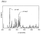
- the present inventors discovered and confirmed via experiments that if the second compound phase was produced with the amount of carbon in the alloy, the composition ranges of other components and the conditions of the heat treatment process for crystallization adjusted appropriately and if the intensity ratio of the diffraction peak of the second compound phase to that of the R 2 Fe 14 B type compound phase representing a (410) plane (and having an interplanar spacing of 0.214 nm) was at least 10%, sufficiently good magnetic properties were achieved in practice. In order to achieve even better magnetic properties, this peak intensity ratio is preferably 30% or more, and even more preferably 50% or more.
- R-T-B-C based rare-earth alloy magnetic materials to which carbon (C) is added intentionally, have already been reported.
- the second compound phase having such a diffraction peak has never been observed. The reason is believed to be as follows. Specifically, the second compound phase being produced is sensible to the composition of the material alloy or the heat treatment condition. Accordingly, if the rare-earth alloy magnetic material is made under normal conditions, then no second compound phase having such a diffraction peak will be produced. Or even if that compound phase is produced, its amount will be very small.
- the second compound is produced by adding an appropriate amount of carbon to the material alloy such that carbon substitutes for a portion of boron in the alloy. Then, the magnetic properties such as the remanence thereof improve and the weather resistance thereof increases.
- the carbon component which has been treated as an impurity, can be incorporated as an indispensable component.
- the present invention is applicable for use in recycling an R-T-B based sintered magnet or an R-T-B based bonded magnet. That is to say, a material alloy including carbon component can be obtained from the used and collected R-T-B based sintered or bonded magnet, and then efficiently processed into an R-T-B-C based rare-earth alloy magnetic material according to the present invention.
- a bonded magnet in particular, normally uses a resin as a binder to bond magnetic powder particles together as described above.
- a carbon based substance often sticks strongly to the surface of the magnet.
- even such a magnet can also be used effectively as a material according to the present invention.
- the present inventors confirmed that the magnetic material of the present invention exhibited not only excellent magnetic properties but also good quality in weather resistance, for example.
- the total amount of boron and carbon is preferably 0.9 wt% to 1.1 wt%, while the carbon ratio (i.e., C/(B+ C)) is preferably 0.05 to 0.75.
- a portion of Fe included in the material of the present invention may be replaced with at least one element selected from the group consisting of Co, Ni, Mn, Cr and Al. Also, at least one element selected from the group consisting of Si, P, Cu, Sn, Ti, Zr, V, Nb, Mo and Ga may be added thereto.
- FIG. 1(a) includes a material alloy melting chamber 1 and a material alloy quenching chamber 2, in which a vacuum or an inert atmosphere is maintained at an adjustable pressure.
- FIG. 1(a) illustrates an overall arrangement of the machine, while FIG. 1(b) illustrates a portion of the machine on a larger scale.
- the melting chamber 1 includes: a melt crucible 3 to melt, at an elevated temperature, a material 20 that has been mixed to have a desired magnet alloy composition; a reservoir 4 with a teeming nozzle 5 at the bottom; and a mixed material feeder 8 to supply the mixed material into the melt crucible 3 while maintaining an airtight condition.
- the reservoir 4 stores the melt 21 of the material alloy therein and is provided with a heater (not shown) to maintain the temperature of the melt teemed therefrom at a predetermined level.
- the quenching chamber 2 includes a rotating chill roller 7 for rapidly quenching and solidifying the melt 21 that has been ejected through the teeming nozzle 5 .
- the atmosphere and pressure inside of the melting and quenching chambers 1 and 2 are controllable within prescribed ranges.
- atmospheric gas inlet ports 1b, 2b and 8b and outlet ports 1a, 2a and 8a are provided at appropriate positions of the machine.
- the gas outlet port 2a is connected to a pump to control the absolute pressure in the quenching chamber 2 within a range of vacuum to 80 kPa.
- the melt crucible 3 may define a desired tilt angle to pour the melt 21 through a funnel 6 into the reservoir 4 .
- the melt 21 is heated in the reservoir 4 by the heater (not shown).
- the teeming nozzle 5 of the reservoir 4 is positioned on the boundary wall between the melting and quenching chambers 1 and 2 to drip the melt 21 from the reservoir 4 onto the surface of the chill roller 7 , which is located under the nozzle 5 .
- the orifice diameter of the teeming nozzle 5 may be 0.5 mm to 2.0 mm, for example. If the viscosity of the melt 21 is high, then the melt 21 cannot flow through the teeming nozzle 5 easily. In this embodiment, however, the pressure in the quenching chamber 2 is kept lower than the pressure in the melting chamber 1 . Accordingly, an appropriate pressure difference is created between the melting and quenching chambers 1 and 2 , and the melt 21 can be teemed smoothly.
- the material alloy of the present invention includes carbon, the molten alloy has so low viscosity as to drip constantly enough.
- the chill roller 7 is preferably made of Cu, Fe or an alloy including Cu or Fe. This is because if the chill roller is made of a material other than Cu or Fe, the resultant rapidly solidified alloy cannot leave the chill roller easily and might wind around the roller.
- the chill roller 7 may have a diameter of 300 mm to 500 mm, for instance.
- the water-cooling capability of a water cooler provided inside of the chill roller 7 is calculated and adjusted based on the latent heat of solidification and the volume of the melt teemed per unit time.
- the machine shown in FIGS. 1(a) and 1(b) can rapidly solidify 10 kg of material alloy in 10 to 20 minutes, for example.
- the rapidly solidified alloy obtained in this manner is in the form of an alloy thin strip (or alloy ribbon) 22 with a thickness of 10 ⁇ m to 300 ⁇ m and a width of 2 mm to 3 mm, for example.
- the melt 21 of the material alloy having the composition described above, is prepared and stored in the reservoir 4 of the melting chamber 1 shown in FIG. 1(a) .
- carbon is introduced into the material alloy by adding ferrocarbon thereto.
- the material alloy may also be obtained from collected and used rare-earth sintered magnets or bonded magnets.
- the melt 21 is dripped through the teeming nozzle 5 onto the water-cooled roller 7 to contact with, and be rapidly cooled and solidified by, the chill roller 7 within a low-pressure Ar atmosphere.
- an appropriate rapid solidification technique making the cooling rate controllable precisely, is preferably adopted.
- the melt 21 is preferably cooled at a rate of 10 2 °C/s to 10 7 °C/s.
- a period of time during which the melt 21 is quenched by the chill roller 7 is equivalent to an interval between a point in time the alloy contacted with the outer circumference of the rotating chill roller 7 and a point in time the alloy leaves the roller 7 .
- the alloy has its temperature decreased to be solidified.
- the solidified alloy leaves the chill roller 7 and travels within the inert atmosphere. While the thin-strip alloy is traveling, the alloy has its heat dissipated into the atmospheric gas. As a result, the temperature of the alloy further drops.
- a rapidly solidified alloy including amorphous phases is obtained by controlling the roller surface velocity within the range of 5 m/s to 50 m/s.
- the reasons are as follows. Specifically, if the roller surface velocity is less than 5 m/s, then crystalline phases with excessively large sizes nucleate and grow and the desired microcrystalline structure cannot be formed. However, a roller surface velocity exceeding 50 m/s is normally hard to realize by mass producible equipment. Also, even if such a high roller surface velocity could be realized, the magnetic properties should not improve so dramatically.
- the roller surface velocity is more preferably 20 m/s to 50 m/s.
- the technique of rapidly quenching the melt is not limited to the single roller melt-spinning method described above.
- other applicable techniques include a twin roller method, a gas atomization method, a strip casting method, and a rapid quenching technique utilizing the roller and gas atomization methods in combination.
- the material alloy includes carbon, and therefore amorphous phases can be created more efficiently.
- a rapidly solidified alloy including a lot of amorphous phases can still be produced with high reproducibility.
- a magnetic alloy with excellent magnetic properties can be obtained even by a strip casting process, which ensures high mass productivity but a relatively low cooling rate among various rapid quenching techniques mentioned above.
- the heat treatment is conducted within an argon atmosphere.
- the alloy is heated at a temperature rise rate of 5 °C/s to 200 °C/s, maintained at a temperature of 550 °C to 750 °C for an amount of time of 30 seconds to 60 minutes, and then cooled to room temperature.
- This heat treatment results in crystal growth of the R 2 Fe 14 B crystalline phase and second compound phase in the amorphous phases.
- the heat treatment temperature is preferably 550 °C to 750 °C, more preferably 550 °C to 700 °C.
- the heat treatment is preferably conducted within an inert gas (e.g., Ar or N 2 gas) atmosphere at a pressure of 50 kPa or less.
- the heat treatment may also be performed within a vacuum of 0.1 kPa or less.
- the thin strip of the rapidly solidified alloy may be coarsely cut or pulverized before subjected to the heat treatment.
- the resultant magnetic material is finely pulverized to obtain a magnet powder.
- various types of bonded magnets can be made from this powder by performing known process steps on this powder.
- the magnet powder of the present invention is compounded with an epoxy or nylon resin binder and then the compound is molded into a desired shape.
- a magnet powder of any other type e.g., an Sm-T-N based magnet powder or hard ferrite magnet powder
- the magnet powder is preferably pulverized to a mean particle size of 150 ⁇ m or less, more preferably 1 ⁇ m to 100 ⁇ m.
- the powder is preferably pulverized to a mean particle size of 300 ⁇ m or less, more preferably 50 ⁇ m to 200 ⁇ m, and even more preferably 50 ⁇ m to 150 ⁇ m with a bimodal size distribution.
- mother alloys having the respective compositions shown in the following Table 1 were prepared by an induction melting process.
- a raw material with a purity of 99.5% or more was used for Nd
- ferrocarbon including 3.0 mass% of carbon was used for carbon
- a raw material with a purity of 99.9% or more was used for each of the other components.
- the material alloy was melted in an alumina crucible within an Ar atmosphere.
- mother alloy E No carbon (C) was added to mother alloy E .
- mother alloy I boron (B) was entirely replaced with carbon (C) .
- the content of Nd in mother alloy A was 25 wt%, which was the smallest among the mother alloys shown in Table 1.
- the content of Nd in mother alloy O was 35 wt%, which was larger than any other mother alloy shown in Table 1.
- the melt of each of these mother alloys A through O was rapidly cooled and solidified by a single roller process, thereby obtaining a thin strip of rapidly solidified alloy.
- a chill roller for use in the rapid quenching process was made of Cu, and was rotated at a peripheral velocity of 35 m/s.
- the mother alloy was melted in a quartz tube having an orifice with a diameter of 0.7 mm. The distance (or the gap) between the end of the orifice of the quartz tube and the roller surface was defined at 0.5 mm.
- the rapid quenching atmosphere was Ar gas at a pressure of 50 kPa.
- the Ar gas used had a differential pressure of 50 kPa to eject the melt strongly enough.
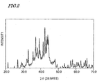
- FIGS. 2 and 3 are graphs each showing the XRD pattern of a rapidly solidified thin strip, which was measured with a CuK ⁇ radiation source before being thermally treated and crystallized.
- the abscissa represents the diffraction angle 2 ⁇ and the ordinate represents the diffraction intensity.
- FIG. 2 relates to a comparative example in which mother alloy E including no additive carbon (C) was used
- FIG. 3 relates to an example of the present invention in which mother alloy G including an appropriate amount of carbon was used.
- Each of the rapidly solidified alloy thin strips obtained by the rapid quenching process included a lot of crystalline phases as can be seen from XRD data shown in FIGS. 2 and 3 , and had a coercivity H cJ of 100 kA/m or less.
- Such a rapidly solidified alloy thin strip was pulverized with an agate mortar to a size of 500 ⁇ m or less, and then subjected to a heat treatment process for crystallization so as to be maintained at a temperature of 500 °C to 1,000 °C for 30 minutes within an Ar atmosphere.
- the thermally treated powders were subjected to magnetic property evaluation with a VSM and X-ray diffraction analysis. The results are shown in the following Table 2: No.
- FIGS. 4 and 5 are graphs each showing the XRD pattern of the rapidly solidified thin strip that was already subjected to the heat treatment for crystallization.
- FIG. 4 relates to Sample No. 22 as a comparative example in which mother alloy E including no additive carbon (C) was used
- FIG. 5 relates to Sample No. 8 as an example of the present invention in which mother alloy G including an appropriate amount of carbon was used.
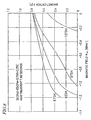
- FIG. 6 shows how the magnetic properties of an R-T-B-C based rare-earth alloy magnetic material represented by the formula Nd 30.0 Fe 69.0 B (1.0-X) C X changed with the carbon ratio X that fell within the range of 0 to 0.75.
- the magnetic material was thermally treated at 873 K for 300 seconds.
- the abscissa represents the external magnetic field H ex in MA/m and the ordinate represents the magnetization J in tesla (T).
- FIG. 7 is a graph similar to FIG. 6 and shows how the magnetic properties of an R-T-B-C based rare-earth alloy magnetic material represented by the formula Nd 30.0 Fe 59.0 Co 10.0 B (1.0-X) C X changed with the carbon ratio X that fell within the range of 0 to 0.75.
- the magnetic material was also thermally treated at 873 K for 300 seconds. As can be seen from FIG. 7, sufficiently good magnetic properties were achieved in the X range of 0.25 to 0.75.
- FIG. 8 shows how the magnetic properties of an R-T-B-C based rare-earth alloy magnetic material represented by the formula Nd 30.0 Fe 69.0 B 0.75 C 0.25 changed with the heat treatment temperature T that fell within the range of 873 K to 1,073 K (i.e., 600 °C to 800 °C). As can be seen from FIG. 8, the magnetic properties deteriorated when the heat treatment temperature was 1,073 K (or 800 °C).
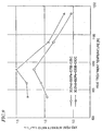
- FIG. 9 shows how the peak intensity ratio of an R-T-B-C based rare-earth alloy magnetic material represented by either Nd 30.0 Fe 69.0 B 0.75 C 0.25 or Nd 30.0 Fe 69.0 B 0.50 C 0.50 changed with a heat treatment temperature T falling within a broad range.
- an R-T-B-C based rare-earth alloy magnetic material including carbon (C) but exhibiting excellent magnetic properties.
- the collected rare-earth magnet is a sintered magnet or a bonded magnet, the collected magnet can be recycled into a magnetic material (in the form of thin strip or powder).
- valuable natural resources can be used more effectively and the manufacturing cost of magnets can be reduced significantly.
- the additive carbon decreases the oxidation reactivity of the rare-earth magnet.
- the magnet performance will not deteriorate due to heat generation or ignition during the manufacturing process or the safety of the manufacturing process will not be endangered.
- the deterioration of the magnet with time can be minimized even without providing any special protective coating on the surface of the magnet to improve the weather resistance thereof.
Landscapes
- Engineering & Computer Science (AREA)
- Power Engineering (AREA)
- Manufacturing & Machinery (AREA)
- Chemical & Material Sciences (AREA)
- Crystallography & Structural Chemistry (AREA)
- Inorganic Chemistry (AREA)
- Hard Magnetic Materials (AREA)
- Manufacture Of Metal Powder And Suspensions Thereof (AREA)
- Powder Metallurgy (AREA)
Abstract
Description
| wt% | |||||||
| Sign | Nd | Fe | Co | B | C | M1 | M2 |
| A | 25.0 | 74.2 | 0.0 | 0.40 | 0.40 | ||
| B | 27.0 | 72.1 | 0.0 | 0.45 | 0.45 | ||
| C | 27.0 | 71.8 | 0.0 | 0.60 | 0.60 | ||
| D | 28.0 | 71.1 | 0.0 | 0.55 | 0.35 | ||
| E | 30.0 | 69.0 | 0.0 | 1.00 | 0.00 | ||
| F | 30.0 | 69.0 | 0.0 | 0.75 | 0.25 | ||
| G | 30.0 | 69.0 | 0.0 | 0.50 | 0.50 | ||
| H | 30.0 | 69.0 | 0.0 | 0.75 | 0.25 | ||
| I | 30.0 | 69.0 | 0.0 | 0.00 | 1.00 | ||
| J | 30.0 | 68.6 | 0.0 | 0.75 | 0.25 | Al:0.40 | |
| K | 30.0 | 68.2 | 0.0 | 0.75 | 0.25 | Al:0.50 | Cu:0.30 |
| L | 30.0 | 63.5 | 5.0 | 0.75 | 0.25 | Ga:0.50 | |
| M | 30.0 | 63.2 | 5.0 | 0.75 | 0.25 | Mo:0.80 | |
| N | 30.0 | 58.4 | 10.0 | 0.50 | 0.50 | Cr:0.30 | Al:0.30 |
| O | 35.0 | 63.8 | 0.0 | 0.60 | 0.60 |
| No. | Mother Alloy | Heat Treatment Temperature (°C) | Magnetic Properties | Diffraction aroundd=0.298 nm | |
| Br (T) | HcJ (kA/m) | ||||
| 1 | B | 600 | 0.90 | 890 | ○ |
| 2 | D | 600 | 0.88 | 1140 | ○ |
| 3 | F | 560 | 0.77 | >1200 | o ○ |
| 4 | F | 610 | 0.78 | >1200 | o ○ |
| 5 | F | 650 | 0.76 | 1170 | o ○ |
| 6 | F | 700 | 0.73 | 1030 | o ○ |
| 7 | G | 570 | 0.74 | >1200 | o ○ |
| 8 | G | 600 | 0.71 | >1200 | o ○ |
| 9 | H | 580 | 0.74 | >1200 | o ○ |
| 10 | H | 620 | 0.70 | 1190 | o ○ |
| 11 | H | 700 | 0.70 | 1050 | o ○ |
| 12 | J | 570 | 0.78 | >1200 | o ○ |
| 13 | J | 650 | 0.79 | >1200 | o ○ |
| 14 | K | 610 | 0.79 | >1200 | o ○ |
| 15 | L | 610 | 0.76 | >1200 | o ○ |
| 16 | M | 600 | 0.72 | >1200 | o ○ |
| 17 | N | 600 | 0.70 | >1200 | o ○ |
| 18 | N | 700 | 0.68 | >1200 | o ○ |
| 19 | C | 600 | 0.78 | 470 | Δ |
| 20 | A | 600 | 0.67 | 180 | × |
| 21 | O | 600 | 0.61 | >1200 | o ○ |
| 22 | E | 600 | 0.73 | >1200 | × |
| 23 | I | 600 | 0.50 | 150 | × |
| 24 | G | 500 | 0.42 | 120 | × |
| 25 | | 800 | 0.35 | 210 | Δ |
Claims (17)
- An R-T-B-C based rare-earth alloy magnetic material (where R is at least one of the rare-earth elements including Y, T is a transition metal including iron as its main ingredient, B is boron, and C is carbon) comprising
a first compound phase with an R2Fe14B type crystal structure, and
a second compound phase having a diffraction peak at a site with an interplanar spacing d of 0.295 nm to 0.300 nm,
wherein an intensity ratio of the diffraction peak of the second compound phase to that of the first compound phase representing a (410) plane (and having an interplanar spacing of 0.214 nm) is at least 10%. - The R-T-B-C based rare-earth alloy magnetic material of claim 1, wherein the mole fraction of R is 25 wt% to 35 wt% of the overall magnetic material, and
wherein the total mole fraction of B and C is 0.9 wt% to 1.1 wt% of the magnetic material, and
wherein the balance of the magnetic material is T. - The R-T-B-C based rare-earth alloy magnetic material of claim 1 or 2, wherein the ratio of the content of C (carbon) to the total content of B (boron) and C is 0.05 to 0.75.
- The R-T-B-C based rare-earth alloy magnetic material of one of claims 1 to 3, wherein the first compound phase has an average grain size of 10 nm to 500 nm.
- The R-T-B-C based rare-earth alloy magnetic material of one of claims 1 to 4, wherein the magnetic material is obtained by a method including the steps of: making a rapidly solidified alloy by rapidly quenching a melt of an R-T-B-C based rare-earth alloy; and thermally treating and crystallizing the rapidly solidified alloy.
- The R-T-B-C based rare-earth alloy magnetic material of one of claims 1 to 5, wherein a portion of Fe included in T is replaced with at least one element selected from the group consisting of Co, Ni, Mn, Cr and Al.
- The R-T-B-C based rare-earth alloy magnetic material of one of claims 1 to 6, further comprising, as an additive, at least one element selected from the group consisting of Si, P, Cu, Sn, Ti, Zr, V, Nb, Mo and Ga.
- A rare-earth alloy magnetic powder obtained by pulverizing the R-T-B-C based rare-earth alloy magnetic material of one of claims 1 to 7.
- A bonded magnet produced by processing the rare-earth alloy magnetic powder of claim 5.
- A permanent magnet produced by processing the rare-earth alloy magnetic powder of claim 8.
- A method of making an R-T-B-C based rare-earth alloy magnetic material, the method comprising the steps of:wherein the step of thermally treating results in producing a first compound phase with an R2Fe14B type crystal structure and a second compound phase having a diffraction peak at a site with an interplanar spacing d of 0.295 nm to 0.300 nm, andpreparing a rapidly solidified alloy by rapidly quenching a melt of an R-T-B-C based rare-earth alloy (where R is at least one of the rare-earth elements including Y, T is a transition metal including iron as its main ingredient, B is boron, and C is carbon); andthermally treating and crystallizing the rapidly solidified alloy,
wherein an intensity ratio of the diffraction peak of the second compound phase to that of the first compound phase representing a (410) plane is at least 10%. - A method of making an R-T-B-C based rare-earth alloy magnetic material, the method comprising the step of obtaining the R-T-B-C based rare-earth alloy magnetic material, including a first compound phase with an R2Fe14B type crystal structure and a second compound phase having a diffraction peak at a site with an interplanar spacing d of 0.295 nm to 0.300 nm, by rapidly quenching a melt of an R-T-B-C based rare-earth alloy (where R is at least one of the rare-earth elements including Y, T is a transition metal including iron as its main ingredient, B is boron, and C is carbon), wherein an intensity ratio of the diffraction peak of the second compound phase to that of the first compound phase representing a (410) plane is at least 10%.
- The method of claim 11, further comprising a pulverizing process step before and/or after the step of thermally treating.
- A method for producing a bonded magnet, the method comprising the steps of:preparing a powder of the R-T-B-C based rare-earth alloy magnetic material that has been obtained by the method of one of claims 11 to 13; andcompounding the powder and a binder material together and molding the compound.
- A method of making an R-T-B-C based rare-earth alloy magnetic material, the method comprising the steps of:preparing an R-T-B-C based rare-earth rapidly solidified alloy (where R is at least one of the rare-earth elements including Y, T is a transition metal including iron as its main ingredient, B is boron, and C is carbon) by melting and rapidly quenching and solidifying a collected and used R-T-B based rare-earth magnet; andthermally treating and crystallizing the R-T-B-C based rare-earth rapidly solidified alloy.
- The method of claim 15, wherein the step of thermally treating results in producing a first compound phase with an R2Fe14B type crystal structure and a second compound phase having a diffraction peak at a site with an interplanar spacing d of 0.295 nm to 0.300 nm, and
wherein an intensity ratio of the diffraction peak of the second compound phase to that of the first compound phase representing a (410) plane is at least 10%. - A method for producing a bonded magnet, the method comprising the steps of:preparing a powder of the R-T-B-C based rare-earth alloy magnetic material that has been obtained by the method of claim 15 or 16; andcompounding the powder and a binder material together and molding the compound.
Applications Claiming Priority (1)
| Application Number | Priority Date | Filing Date | Title |
|---|---|---|---|
| PCT/JP2001/005688 WO2003003386A1 (en) | 2001-06-29 | 2001-06-29 | R-t-b-c based rare earth magnetic powder and bonded magnet |
Publications (3)
| Publication Number | Publication Date |
|---|---|
| EP1411532A1 true EP1411532A1 (en) | 2004-04-21 |
| EP1411532A4 EP1411532A4 (en) | 2008-10-29 |
| EP1411532B1 EP1411532B1 (en) | 2014-11-26 |
Family
ID=32040292
Family Applications (1)
| Application Number | Title | Priority Date | Filing Date |
|---|---|---|---|
| EP01945740.7A Expired - Lifetime EP1411532B1 (en) | 2001-06-29 | 2001-06-29 | R-t-b-c based rare earth magnetic powder and bonded magnet |
Country Status (5)
| Country | Link |
|---|---|
| US (1) | US7316752B2 (en) |
| EP (1) | EP1411532B1 (en) |
| JP (1) | JP2001355050A (en) |
| CN (1) | CN1254828C (en) |
| WO (1) | WO2003003386A1 (en) |
Cited By (1)
| Publication number | Priority date | Publication date | Assignee | Title |
|---|---|---|---|---|
| US9225758B2 (en) | 2008-05-26 | 2015-12-29 | Thomson Licensing | Simplified transmission method for a stream of signals between a transmitter and an electronic device |
Families Citing this family (13)
| Publication number | Priority date | Publication date | Assignee | Title |
|---|---|---|---|---|
| JP2002285276A (en) * | 2001-03-26 | 2002-10-03 | Hitachi Metals Ltd | RTBC based sintered magnet and method of manufacturing the same |
| JP2005302745A (en) * | 2001-12-27 | 2005-10-27 | Osaka Industrial Promotion Organization | Rare earth bonded magnet powder manufacturing method and bonded magnet manufacturing method using the same |
| JP4543940B2 (en) * | 2005-01-25 | 2010-09-15 | Tdk株式会社 | Method for producing RTB-based sintered magnet |
| EP2394175B1 (en) * | 2009-02-09 | 2016-02-03 | caprotec bioanalytics GmbH | Devices, systems and methods for separating magnetic particles |
| JP5288277B2 (en) * | 2009-08-28 | 2013-09-11 | 日立金属株式会社 | Manufacturing method of RTB-based permanent magnet |
| JP5288276B2 (en) * | 2009-08-28 | 2013-09-11 | 日立金属株式会社 | Manufacturing method of RTB-based permanent magnet |
| WO2011053352A1 (en) * | 2009-10-30 | 2011-05-05 | Iowa State University Research Foundation, Inc. | Method for producing permanent magnet materials and resulting materials |
| WO2012011946A2 (en) | 2010-07-20 | 2012-01-26 | Iowa State University Research Foundation, Inc. | Method for producing la/ce/mm/y base alloys, resulting alloys, and battery electrodes |
| WO2013114892A1 (en) * | 2012-02-02 | 2013-08-08 | 中電レアアース株式会社 | R-T-B-Ga-BASED MAGNET MATERIAL ALLOY AND METHOD FOR PRODUCING SAME |
| CN104823249B (en) * | 2013-05-31 | 2018-01-05 | 北京有色金属研究总院 | The device of rare earth permanent magnet powder including its bonded permanent magnet and the application bonded permanent magnet |
| US9336932B1 (en) * | 2014-08-15 | 2016-05-10 | Urban Mining Company | Grain boundary engineering |
| DE102016216355A1 (en) | 2016-08-30 | 2018-03-01 | Fraunhofer-Gesellschaft zur Förderung der angewandten Forschung e.V. | Process for recycling permanent magnets by melting and rapid solidification |
| CN116855815B (en) * | 2023-03-14 | 2026-02-13 | 北京工业大学 | A method for improving the phase stability of rare-earth permanent magnet material Pr2Fe14C to reduce the harm of residual carbon. |
Family Cites Families (18)
| Publication number | Priority date | Publication date | Assignee | Title |
|---|---|---|---|---|
| JP2625163B2 (en) | 1988-08-05 | 1997-07-02 | ゼネラル・モーターズ・コーポレーション | Manufacturing method of permanent magnet powder |
| JP2739525B2 (en) | 1991-02-22 | 1998-04-15 | 同和鉱業株式会社 | R-Fe-BC permanent magnet alloy with low irreversible demagnetization and excellent thermal stability |
| JPH04268703A (en) | 1991-02-24 | 1992-09-24 | Dowa Mining Co Ltd | R-Fe-B-C bonded magnet with excellent oxidation resistance |
| JP3023881B2 (en) | 1991-02-26 | 2000-03-21 | 同和鉱業株式会社 | R-Fe-BC bonded magnet with excellent oxidation resistance |
| JPH05105901A (en) | 1991-10-11 | 1993-04-27 | Kanegafuchi Chem Ind Co Ltd | Corrosion resistance rare earth magnet material |
| JP2818718B2 (en) | 1992-10-28 | 1998-10-30 | ゼネラル・モーターズ・コーポレーション | Permanent magnet powder |
| JP2753429B2 (en) * | 1992-10-28 | 1998-05-20 | ゼネラル・モーターズ・コーポレーション | Bonded magnet |
| JP2753430B2 (en) | 1992-10-28 | 1998-05-20 | ゼネラル・モーターズ・コーポレーション | Bonded magnet |
| JPH0778706A (en) | 1993-09-06 | 1995-03-20 | Tdk Corp | Magnet and its manufacture, and bonded magnet |
| US5486240A (en) * | 1994-04-25 | 1996-01-23 | Iowa State University Research Foundation, Inc. | Carbide/nitride grain refined rare earth-iron-boron permanent magnet and method of making |
| JP4302198B2 (en) | 1997-03-25 | 2009-07-22 | 明久 井上 | Fe-based hard magnetic alloy with supercooled liquid region |
| EP0867897B1 (en) | 1997-03-25 | 2003-11-26 | Alps Electric Co., Ltd. | Fe based hard magnetic alloy having super-cooled liquid region |
| JP2000223306A (en) | 1998-11-25 | 2000-08-11 | Hitachi Metals Ltd | R-T-B rare earth sintered magnet with improved squareness ratio and method of manufacturing the same |
| CN1142560C (en) | 1999-09-14 | 2004-03-17 | 北京大学 | Multielement gap type permanent-magnet material and production process of magnetic powler and magnet |
| JP2001118710A (en) | 1999-10-15 | 2001-04-27 | Matsushita Electric Ind Co Ltd | Rare earth resin magnet and magnet rotor |
| JP4265056B2 (en) * | 1999-11-12 | 2009-05-20 | パナソニック株式会社 | Recovery and reuse of magnetic powder from rare earth bonded magnets |
| KR100562681B1 (en) * | 2000-05-24 | 2006-03-23 | 가부시키가이샤 네오맥스 | Permanent magnets comprising a plurality of ferromagnetic properties and a method of manufacturing the same |
| WO2002004714A1 (en) * | 2000-07-07 | 2002-01-17 | Hitachi Metals, Ltd. | Electrolytic copper-plated r-t-b magnet and plating method thereof |
-
2000
- 2000-06-12 JP JP2000175800A patent/JP2001355050A/en active Pending
-
2001
- 2001-06-29 US US10/481,015 patent/US7316752B2/en not_active Expired - Lifetime
- 2001-06-29 EP EP01945740.7A patent/EP1411532B1/en not_active Expired - Lifetime
- 2001-06-29 WO PCT/JP2001/005688 patent/WO2003003386A1/en not_active Ceased
- 2001-06-29 CN CN01823266.3A patent/CN1254828C/en not_active Expired - Lifetime
Cited By (1)
| Publication number | Priority date | Publication date | Assignee | Title |
|---|---|---|---|---|
| US9225758B2 (en) | 2008-05-26 | 2015-12-29 | Thomson Licensing | Simplified transmission method for a stream of signals between a transmitter and an electronic device |
Also Published As
| Publication number | Publication date |
|---|---|
| US7316752B2 (en) | 2008-01-08 |
| EP1411532B1 (en) | 2014-11-26 |
| JP2001355050A (en) | 2001-12-25 |
| CN1254828C (en) | 2006-05-03 |
| EP1411532A4 (en) | 2008-10-29 |
| WO2003003386A1 (en) | 2003-01-09 |
| US20040168747A1 (en) | 2004-09-02 |
| CN1507636A (en) | 2004-06-23 |
Similar Documents
| Publication | Publication Date | Title |
|---|---|---|
| US7842140B2 (en) | Iron-based rare-earth nanocomposite magnet and method for producing the magnet | |
| EP1358660B1 (en) | Method of making material alloy for iron-based rare earth magnet | |
| EP1446816B1 (en) | Nanocomposite magnet | |
| US7208097B2 (en) | Iron-based rare earth alloy nanocomposite magnet and method for producing the same | |
| EP1158545B1 (en) | Permanent magnet including multiple ferromagnetic phases and method for producing the magnet | |
| EP0886284B1 (en) | Cast alloy used for production of rare earth magnet and method for producing cast alloy and magnet | |
| EP2513917B1 (en) | Rare earth magnet and manufacturing method therefor | |
| JP2003049204A (en) | Iron-based rare earth alloy powder, compound containing iron-based rare earth alloy powder, and permanent magnet using the same | |
| US7316752B2 (en) | R-T-B-C based rare-earth magnetic powder and bonded magnet | |
| EP1479787B1 (en) | Sinter magnet made from rare earth-iron-boron alloy powder for magnet | |
| RU2311698C2 (en) | Nano-composite magnet and its manufacturing process | |
| EP1762632B1 (en) | Iron-based rare-earth-containing nanocomposite magnet and process for producing the same | |
| WO2020022955A1 (en) | Alloys, magnetic materials, bonded magnets and methods for producing the same | |
| JP3801456B2 (en) | Iron-based rare earth permanent magnet alloy and method for producing the same | |
| JP4120253B2 (en) | Quenched alloy for nanocomposite magnet and method for producing the same | |
| US20090129966A1 (en) | Iron-based rare-earth-containing nanocomposite magnet and process for producing the same | |
| JP2002212686A (en) | Quenched alloy for iron-based rare earth alloy magnet and method for producing iron-based rare earth alloy magnet | |
| JP4715245B2 (en) | Iron-based rare earth nanocomposite magnet and method for producing the same | |
| JP2003221655A (en) | Nano composite magnet | |
| JP2003158005A (en) | Nanocomposite magnet and method of manufacturing the same |
Legal Events
| Date | Code | Title | Description |
|---|---|---|---|
| PUAI | Public reference made under article 153(3) epc to a published international application that has entered the european phase |
Free format text: ORIGINAL CODE: 0009012 |
|
| 17P | Request for examination filed |
Effective date: 20040123 |
|
| AK | Designated contracting states |
Kind code of ref document: A1 Designated state(s): AT BE CH CY DE DK ES FI FR GB GR IE IT LI LU MC NL PT SE TR |
|
| RAP1 | Party data changed (applicant data changed or rights of an application transferred) |
Owner name: NEOMAX CO., LTD. |
|
| RAP1 | Party data changed (applicant data changed or rights of an application transferred) |
Owner name: HITACHI METALS, LTD. |
|
| A4 | Supplementary search report drawn up and despatched |
Effective date: 20081001 |
|
| RIC1 | Information provided on ipc code assigned before grant |
Ipc: H01F 1/058 20060101AFI20080925BHEP Ipc: H01F 1/057 20060101ALI20080925BHEP |
|
| 17Q | First examination report despatched |
Effective date: 20090302 |
|
| GRAP | Despatch of communication of intention to grant a patent |
Free format text: ORIGINAL CODE: EPIDOSNIGR1 |
|
| INTG | Intention to grant announced |
Effective date: 20140630 |
|
| GRAS | Grant fee paid |
Free format text: ORIGINAL CODE: EPIDOSNIGR3 |
|
| GRAA | (expected) grant |
Free format text: ORIGINAL CODE: 0009210 |
|
| AK | Designated contracting states |
Kind code of ref document: B1 Designated state(s): AT BE CH CY DE DK ES FI FR GB GR IE IT LI LU MC NL PT SE TR |
|
| REG | Reference to a national code |
Ref country code: GB Ref legal event code: FG4D |
|
| REG | Reference to a national code |
Ref country code: CH Ref legal event code: EP |
|
| REG | Reference to a national code |
Ref country code: AT Ref legal event code: REF Ref document number: 698598 Country of ref document: AT Kind code of ref document: T Effective date: 20141215 |
|
| REG | Reference to a national code |
Ref country code: IE Ref legal event code: FG4D |
|
| REG | Reference to a national code |
Ref country code: DE Ref legal event code: R096 Ref document number: 60149134 Country of ref document: DE Effective date: 20150108 |
|
| REG | Reference to a national code |
Ref country code: NL Ref legal event code: VDEP Effective date: 20141126 |
|
| REG | Reference to a national code |
Ref country code: AT Ref legal event code: MK05 Ref document number: 698598 Country of ref document: AT Kind code of ref document: T Effective date: 20141126 |
|
| PG25 | Lapsed in a contracting state [announced via postgrant information from national office to epo] |
Ref country code: PT Free format text: LAPSE BECAUSE OF FAILURE TO SUBMIT A TRANSLATION OF THE DESCRIPTION OR TO PAY THE FEE WITHIN THE PRESCRIBED TIME-LIMIT Effective date: 20150326 Ref country code: NL Free format text: LAPSE BECAUSE OF FAILURE TO SUBMIT A TRANSLATION OF THE DESCRIPTION OR TO PAY THE FEE WITHIN THE PRESCRIBED TIME-LIMIT Effective date: 20141126 Ref country code: ES Free format text: LAPSE BECAUSE OF FAILURE TO SUBMIT A TRANSLATION OF THE DESCRIPTION OR TO PAY THE FEE WITHIN THE PRESCRIBED TIME-LIMIT Effective date: 20141126 Ref country code: FI Free format text: LAPSE BECAUSE OF FAILURE TO SUBMIT A TRANSLATION OF THE DESCRIPTION OR TO PAY THE FEE WITHIN THE PRESCRIBED TIME-LIMIT Effective date: 20141126 |
|
| PG25 | Lapsed in a contracting state [announced via postgrant information from national office to epo] |
Ref country code: GR Free format text: LAPSE BECAUSE OF FAILURE TO SUBMIT A TRANSLATION OF THE DESCRIPTION OR TO PAY THE FEE WITHIN THE PRESCRIBED TIME-LIMIT Effective date: 20150227 Ref country code: AT Free format text: LAPSE BECAUSE OF FAILURE TO SUBMIT A TRANSLATION OF THE DESCRIPTION OR TO PAY THE FEE WITHIN THE PRESCRIBED TIME-LIMIT Effective date: 20141126 Ref country code: CY Free format text: LAPSE BECAUSE OF FAILURE TO SUBMIT A TRANSLATION OF THE DESCRIPTION OR TO PAY THE FEE WITHIN THE PRESCRIBED TIME-LIMIT Effective date: 20141126 Ref country code: SE Free format text: LAPSE BECAUSE OF FAILURE TO SUBMIT A TRANSLATION OF THE DESCRIPTION OR TO PAY THE FEE WITHIN THE PRESCRIBED TIME-LIMIT Effective date: 20141126 |
|
| PG25 | Lapsed in a contracting state [announced via postgrant information from national office to epo] |
Ref country code: DK Free format text: LAPSE BECAUSE OF FAILURE TO SUBMIT A TRANSLATION OF THE DESCRIPTION OR TO PAY THE FEE WITHIN THE PRESCRIBED TIME-LIMIT Effective date: 20141126 |
|
| REG | Reference to a national code |
Ref country code: DE Ref legal event code: R097 Ref document number: 60149134 Country of ref document: DE |
|
| PLBE | No opposition filed within time limit |
Free format text: ORIGINAL CODE: 0009261 |
|
| STAA | Information on the status of an ep patent application or granted ep patent |
Free format text: STATUS: NO OPPOSITION FILED WITHIN TIME LIMIT |
|
| 26N | No opposition filed |
Effective date: 20150827 |
|
| PG25 | Lapsed in a contracting state [announced via postgrant information from national office to epo] |
Ref country code: IT Free format text: LAPSE BECAUSE OF FAILURE TO SUBMIT A TRANSLATION OF THE DESCRIPTION OR TO PAY THE FEE WITHIN THE PRESCRIBED TIME-LIMIT Effective date: 20141126 |
|
| PG25 | Lapsed in a contracting state [announced via postgrant information from national office to epo] |
Ref country code: MC Free format text: LAPSE BECAUSE OF FAILURE TO SUBMIT A TRANSLATION OF THE DESCRIPTION OR TO PAY THE FEE WITHIN THE PRESCRIBED TIME-LIMIT Effective date: 20141126 |
|
| REG | Reference to a national code |
Ref country code: CH Ref legal event code: PL |
|
| GBPC | Gb: european patent ceased through non-payment of renewal fee |
Effective date: 20150629 |
|
| PG25 | Lapsed in a contracting state [announced via postgrant information from national office to epo] |
Ref country code: LU Free format text: LAPSE BECAUSE OF FAILURE TO SUBMIT A TRANSLATION OF THE DESCRIPTION OR TO PAY THE FEE WITHIN THE PRESCRIBED TIME-LIMIT Effective date: 20150629 |
|
| REG | Reference to a national code |
Ref country code: IE Ref legal event code: MM4A |
|
| REG | Reference to a national code |
Ref country code: FR Ref legal event code: ST Effective date: 20160229 |
|
| PG25 | Lapsed in a contracting state [announced via postgrant information from national office to epo] |
Ref country code: IE Free format text: LAPSE BECAUSE OF NON-PAYMENT OF DUE FEES Effective date: 20150629 Ref country code: LI Free format text: LAPSE BECAUSE OF NON-PAYMENT OF DUE FEES Effective date: 20150630 Ref country code: GB Free format text: LAPSE BECAUSE OF NON-PAYMENT OF DUE FEES Effective date: 20150629 Ref country code: CH Free format text: LAPSE BECAUSE OF NON-PAYMENT OF DUE FEES Effective date: 20150630 |
|
| PG25 | Lapsed in a contracting state [announced via postgrant information from national office to epo] |
Ref country code: FR Free format text: LAPSE BECAUSE OF NON-PAYMENT OF DUE FEES Effective date: 20150630 |
|
| PG25 | Lapsed in a contracting state [announced via postgrant information from national office to epo] |
Ref country code: TR Free format text: LAPSE BECAUSE OF FAILURE TO SUBMIT A TRANSLATION OF THE DESCRIPTION OR TO PAY THE FEE WITHIN THE PRESCRIBED TIME-LIMIT Effective date: 20141126 |
|
| PG25 | Lapsed in a contracting state [announced via postgrant information from national office to epo] |
Ref country code: BE Free format text: LAPSE BECAUSE OF FAILURE TO SUBMIT A TRANSLATION OF THE DESCRIPTION OR TO PAY THE FEE WITHIN THE PRESCRIBED TIME-LIMIT Effective date: 20141126 |
|
| PGFP | Annual fee paid to national office [announced via postgrant information from national office to epo] |
Ref country code: DE Payment date: 20200617 Year of fee payment: 20 |
|
| REG | Reference to a national code |
Ref country code: DE Ref legal event code: R071 Ref document number: 60149134 Country of ref document: DE |