EP1410724A1 - A unit for preparing leaves of paper material - Google Patents
A unit for preparing leaves of paper material Download PDFInfo
- Publication number
- EP1410724A1 EP1410724A1 EP20030425657 EP03425657A EP1410724A1 EP 1410724 A1 EP1410724 A1 EP 1410724A1 EP 20030425657 EP20030425657 EP 20030425657 EP 03425657 A EP03425657 A EP 03425657A EP 1410724 A1 EP1410724 A1 EP 1410724A1
- Authority
- EP
- European Patent Office
- Prior art keywords
- unit
- roller
- conveyor
- strip
- suction roller
- Prior art date
- Legal status (The legal status is an assumption and is not a legal conclusion. Google has not performed a legal analysis and makes no representation as to the accuracy of the status listed.)
- Withdrawn
Links
Images



Classifications
-
- A—HUMAN NECESSITIES
- A24—TOBACCO; CIGARS; CIGARETTES; SIMULATED SMOKING DEVICES; SMOKERS' REQUISITES
- A24C—MACHINES FOR MAKING CIGARS OR CIGARETTES
- A24C5/00—Making cigarettes; Making tipping materials for, or attaching filters or mouthpieces to, cigars or cigarettes
- A24C5/47—Attaching filters or mouthpieces to cigars or cigarettes, e.g. inserting filters into cigarettes or their mouthpieces
- A24C5/471—Attaching filters or mouthpieces to cigars or cigarettes, e.g. inserting filters into cigarettes or their mouthpieces by means of a connecting band
- A24C5/473—Cutting the connecting band
-
- B—PERFORMING OPERATIONS; TRANSPORTING
- B65—CONVEYING; PACKING; STORING; HANDLING THIN OR FILAMENTARY MATERIAL
- B65H—HANDLING THIN OR FILAMENTARY MATERIAL, e.g. SHEETS, WEBS, CABLES
- B65H20/00—Advancing webs
- B65H20/12—Advancing webs by suction roller
-
- B—PERFORMING OPERATIONS; TRANSPORTING
- B65—CONVEYING; PACKING; STORING; HANDLING THIN OR FILAMENTARY MATERIAL
- B65H—HANDLING THIN OR FILAMENTARY MATERIAL, e.g. SHEETS, WEBS, CABLES
- B65H29/00—Delivering or advancing articles from machines; Advancing articles to or into piles
- B65H29/24—Delivering or advancing articles from machines; Advancing articles to or into piles by air blast or suction apparatus
- B65H29/241—Suction devices
-
- B—PERFORMING OPERATIONS; TRANSPORTING
- B65—CONVEYING; PACKING; STORING; HANDLING THIN OR FILAMENTARY MATERIAL
- B65H—HANDLING THIN OR FILAMENTARY MATERIAL, e.g. SHEETS, WEBS, CABLES
- B65H35/00—Delivering articles from cutting or line-perforating machines; Article or web delivery apparatus incorporating cutting or line-perforating devices, e.g. adhesive tape dispensers
- B65H35/04—Delivering articles from cutting or line-perforating machines; Article or web delivery apparatus incorporating cutting or line-perforating devices, e.g. adhesive tape dispensers from or with transverse cutters or perforators
- B65H35/08—Delivering articles from cutting or line-perforating machines; Article or web delivery apparatus incorporating cutting or line-perforating devices, e.g. adhesive tape dispensers from or with transverse cutters or perforators from or with revolving, e.g. cylinder, cutters or perforators
-
- Y—GENERAL TAGGING OF NEW TECHNOLOGICAL DEVELOPMENTS; GENERAL TAGGING OF CROSS-SECTIONAL TECHNOLOGIES SPANNING OVER SEVERAL SECTIONS OF THE IPC; TECHNICAL SUBJECTS COVERED BY FORMER USPC CROSS-REFERENCE ART COLLECTIONS [XRACs] AND DIGESTS
- Y10—TECHNICAL SUBJECTS COVERED BY FORMER USPC
- Y10T—TECHNICAL SUBJECTS COVERED BY FORMER US CLASSIFICATION
- Y10T83/00—Cutting
- Y10T83/323—With means to stretch work temporarily
-
- Y—GENERAL TAGGING OF NEW TECHNOLOGICAL DEVELOPMENTS; GENERAL TAGGING OF CROSS-SECTIONAL TECHNOLOGIES SPANNING OVER SEVERAL SECTIONS OF THE IPC; TECHNICAL SUBJECTS COVERED BY FORMER USPC CROSS-REFERENCE ART COLLECTIONS [XRACs] AND DIGESTS
- Y10—TECHNICAL SUBJECTS COVERED BY FORMER USPC
- Y10T—TECHNICAL SUBJECTS COVERED BY FORMER US CLASSIFICATION
- Y10T83/00—Cutting
- Y10T83/465—Cutting motion of tool has component in direction of moving work
- Y10T83/4766—Orbital motion of cutting blade
- Y10T83/4795—Rotary tool
- Y10T83/483—With cooperating rotary cutter or backup
- Y10T83/4836—With radial overlap of the cutting members
Definitions
- the present invention relates to a unit for preparing leaves of paper material.
- the invention finds application to advantage in cigarette making machines, and in particular filter tip attachments by which single tipping papers are cut from a continuous strip decoiled from a roll; reference is made explicitly to this art field in the following specification, albeit implying no limitation in general scope.
- Filter tipped cigarettes are assembled generally by interposing a double length filter plug between two axially aligned cigarette sticks, then joining the filter to the sticks on either side by affixing a previously gummed tipping paper, and ultimately cutting the double assembly in half to create two single filter cigarettes.
- tipping papers are obtained from a continuous strip of paper material caused to advance along a predetermined feed path, first through a gumming device by which adhesive is applied to one face of the strip, and thereafter to a cutting device by which the strip is divided up into single leaves of predetermined length.
- the cutting device operates downstream of the gumming device, relative to the direction followed by the advancing strip, and comprises two rollers contrarotating tangentially to one another about parallel axes, one with an aspirating surface by which the strip is drawn forward; each roller is equipped with respective blades arranged angularly at uniform pitch around its peripheral surface.
- each blade presented by one of the two rollers will interact typically with a corresponding blade of the other roller in such a way as to sever the strip along transverse lines, executing a so-called scissor cut. Accordingly, each blade of one roller combines with a blade of the other roller to create a scissor device which, when the rollers are driven in rotation, is designed to separate successive tipping papers by shearing point-to-point across the strip.
- the tipping papers are held on the surface of one of the two rollers, and more exactly the suction roller, before being transferred in succession to a station where each is offered to an aforementioned assembly composed of a double length filter plug and two cigarette sticks.
- the tipping papers cut from the strip must be suitably distanced one from the next; this is accomplished by causing the suction roller to rotate at a peripheral speed greater than the linear speed of the advancing strip.
- the scissor cut is generated by degrees, signifying that the separation of the single paper does not occur instantaneously but only after a given interval of time, the difference between the peripheral speed of the suction roller and the linear speed of the advancing strip prevents the papers being detached cleanly from the strip.
- the traction force exerted by the suction roller in effect, the advancing strip is subjected to a pulling action which the narrowing portion of material gradually becomes unable to withstand as the final stage of the scissor cut is reached and tension in the uncut portion of the strip becomes excessive, so that the tipping paper separates by tearing, before a clean cut can be completed.
- the papers detached in this manner cannot therefore be utilized as they are marred by irregularities along the line of the cut at the point where the final separation occurs.
- prior art methods include the expedient of inserting a cyclically activated diverter between the gumming device and the cutting device, by which the tension of the strip is varied at intervals matching the stroke frequency of the cutting device. More exactly, the diverter serves to relax the tension of the strip during the cutting stroke.
- the object of the invention is to provide a unit for preparing leaves of paper material such as will be unaffected by the aforementioned drawback.
- 1 denotes a portion, in its entirety, of a cigarette maker, and in particular a filter tip attachment, comprising a unit 2 by means of which to prepare leaves 3 of paper material, or tipping papers, obtained from a continuous strip 4 caused to decoil from a relative bulk roll (not indicated) and advance along a predetermined feed path P in a direction denoted D, at a predetermined tension and linear speed.
- the unit 2 comprises cutting means 5 which in turn are composed of a first conveyor 6 consisting in a suction roller 7, and a second conveyor 8 consisting in a second roller 9 turning substantially tangential to the first at a station 10 where the strip 4 is divided into single leaves 3.
- rollers 7 and 9 are mounted to respective horizontal and mutually parallel shafts 11 and 12 carried in a frame 13 presented by the portion 1 of the cigarette maker and rotatable thus in opposite directions, turning clockwise and anticlockwise respectively as viewed in figure 1.
- the second roller 9 carries a plurality of substantially radial blades 14 equispaced around and projecting from its peripheral surface 15, whilst the suction roller 7 comprises a disc 16 keyed onto the relative shaft 11 and furnished at the periphery 17 with a plurality of cantilevered aspirating sectors 18 equispaced angularly around the circumference and extending parallel to the axis of rotation of the roller 7, in such a way that the respective outer surfaces 19 of these same sectors 18 combine to create an outer cylindrical surface 20 that is set in rotation at a peripheral speed greater than the linear speed of the strip 9 advancing along the feed path P.
- each sector 18 presents a plurality of holes 21 connected in conventional manner by way of ducts 22, extending parallel with the shaft 11, to a source of negative pressure not illustrated in the drawings.
- the positioning of the sectors 18 around the periphery 17 of the disc 16, moreover, is such that each remains distanced from the next, with the result that the outer surface 20 of the roller 7 presents a plurality of gaps 23.
- each sector 18 presents a longitudinal corner edge 24 extending parallel to the axis of the first roller 7 and trailing in the direction of rotation, such as will combine with a corresponding blade 14 of the second roller 9 as it penetrates the relative gap 23 during the rotation of the rollers 7 and 9 and, when passing through the cutting station 10, establish a scissor device by which the continuous strip 4 is sheared across to generate a single leaf 3.
- the filter tip attachment also comprises a roller 25 mounted to a shaft 26 lying parallel to the shafts 11 and 12 aforementioned, rotatable clockwise and furnished peripherally with grooves 27 each serving to accommodate a respective assembly 28 of two cigarette sticks separated by a double length filter plug, which is retained by suction in conventional manner; the assemblies 28 are caused to advance on the roller 25 transversely to their own axes through a transfer station 29 at which a tipping paper 3 is released by the suction roller 7 onto the outer surface of each successive assembly 28, whereupon the filters and cigarette sticks are joined together.
- the unit 1 further comprises means 30, associated with the suction roller 7, by which to vary the tension of the continuous strip 4.
- Such means 30 comprise diverter elements consisting in three cylindrical rods 31 extending parallel to the shaft 11 of the roller 7. Each rod 31 is supported at one end by one corresponding arm 32 of a flange 33 presenting three such arms 32 equispaced angularly at 120°.
- the flange 33 is mounted to the projecting end of a shaft 34, rotatable about a relative axis 35 of which the position is fixed, extending parallel to the two roller shafts 11 and 12 and carried by a bulkhead 36 facing the frame 13 in such a way that the rods 31 extend from the flange 33 on the side of the roller 7 opposite to that occupied by the disc 16 supporting the aspirating sectors 18.
- the aspirating sectors 18 and the cylindrical rods 31 are cantilevered from their supporting elements, namely the disc 16 and the flange 33, respectively, which occupy positions of mutual opposition on either side of the feed path P followed by the advancing strip 4.
- the cylindrical rods 31 extend toward the disc 16 through a distance such that their free ends lie in close proximity to the disc and are able to revolve thus around the axis 35, which occupies a fixed position between the axis of the shaft 11 carrying the suction roller 7, and the outer surface 20 of this same roller 7.
- the shaft denoted 34 is coupled to the shaft 11 of the suction roller 7 by way of an interposed train of gears 37, 38 and 39 functioning also as means by which to adjust the timing between the rotation of the suction roller 7 and that of the tension varying means 30 in such a way that the three cylindrical rods 31 can be made to alternate cyclically and at the same frequency as the cutting means 5 between a first limit position radially behind the surface 20 of the suction roller 7 and a second limit position radially beyond the selfsame surface 20, by passing through the aforementioned gaps 23.
- the continuous strip 4 advances at a predetermined linear speed along the feed path P through a gumming station 40 and a guide roller 41, ultimately reaching the outer surface 20 of the suction roller 7 which, in order to distance the leaves 3 separated at the cutting station 10, is caused to rotate at a peripheral speed greater than the linear speed of the advancing strip 4.
- This difference in speed causes the strip 4 positioned upstream of the cutting station 10 to slip on the outer surfaces 19 of the sectors 18, against which it is held by suction.
- next cylindrical rod 31 will pass through the next corresponding gap 23 to begin a new cycle, diverting the strip 4 in readiness for a further leaf 3 to be cut.
Landscapes
- Engineering & Computer Science (AREA)
- Mechanical Engineering (AREA)
- Manufacturing Of Cigar And Cigarette Tobacco (AREA)
Abstract
Description
- The present invention relates to a unit for preparing leaves of paper material.
- The invention finds application to advantage in cigarette making machines, and in particular filter tip attachments by which single tipping papers are cut from a continuous strip decoiled from a roll; reference is made explicitly to this art field in the following specification, albeit implying no limitation in general scope.
- Filter tipped cigarettes are assembled generally by interposing a double length filter plug between two axially aligned cigarette sticks, then joining the filter to the sticks on either side by affixing a previously gummed tipping paper, and ultimately cutting the double assembly in half to create two single filter cigarettes.
- Employing prior art methods, tipping papers are obtained from a continuous strip of paper material caused to advance along a predetermined feed path, first through a gumming device by which adhesive is applied to one face of the strip, and thereafter to a cutting device by which the strip is divided up into single leaves of predetermined length.
- The cutting device operates downstream of the gumming device, relative to the direction followed by the advancing strip, and comprises two rollers contrarotating tangentially to one another about parallel axes, one with an aspirating surface by which the strip is drawn forward; each roller is equipped with respective blades arranged angularly at uniform pitch around its peripheral surface.
- Each blade presented by one of the two rollers will interact typically with a corresponding blade of the other roller in such a way as to sever the strip along transverse lines, executing a so-called scissor cut. Accordingly, each blade of one roller combines with a blade of the other roller to create a scissor device which, when the rollers are driven in rotation, is designed to separate successive tipping papers by shearing point-to-point across the strip.
- After the cut, the tipping papers are held on the surface of one of the two rollers, and more exactly the suction roller, before being transferred in succession to a station where each is offered to an aforementioned assembly composed of a double length filter plug and two cigarette sticks.
- For the operation of joining the assemblies to be performed correctly, the tipping papers cut from the strip must be suitably distanced one from the next; this is accomplished by causing the suction roller to rotate at a peripheral speed greater than the linear speed of the advancing strip.
- Because the scissor cut is generated by degrees, signifying that the separation of the single paper does not occur instantaneously but only after a given interval of time, the difference between the peripheral speed of the suction roller and the linear speed of the advancing strip prevents the papers being detached cleanly from the strip. As a result of the traction force exerted by the suction roller, in effect, the advancing strip is subjected to a pulling action which the narrowing portion of material gradually becomes unable to withstand as the final stage of the scissor cut is reached and tension in the uncut portion of the strip becomes excessive, so that the tipping paper separates by tearing, before a clean cut can be completed. The papers detached in this manner cannot therefore be utilized as they are marred by irregularities along the line of the cut at the point where the final separation occurs.
- To overcome such drawbacks, prior art methods include the expedient of inserting a cyclically activated diverter between the gumming device and the cutting device, by which the tension of the strip is varied at intervals matching the stroke frequency of the cutting device. More exactly, the diverter serves to relax the tension of the strip during the cutting stroke.
- With higher and higher strip feed speeds being adopted to accommodate increasingly fast production tempos, it can happen, due to the inherent elastic properties of the strip of paper material and the vibration generated by the diverter in the length of strip extending between the selfsame diverter and the cutting device, that the steps of relaxing the tension and making the cut will slip out of phase, and there is a risk of the material tearing along the final part of the cutting line.
- The object of the invention is to provide a unit for preparing leaves of paper material such as will be unaffected by the aforementioned drawback.
- The stated object is realized according to the present invention in a unit for preparing leaves of paper material from a continuous strip, of which the characterizing features are as recited in one of more of the claims appended.
- The invention will now be described in detail, by way of example, with the aid of the accompanying drawings, in which:
- figure 1 illustrates a portion of a filter tip attachment equipped with a unit for preparing leaves of paper material embodied in accordance with the present invention, viewed schematically in a front elevation;
- figure 2 illustrates an enlarged detail of the unit shown in figure 1, viewed in perspective;
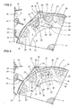
- figures 3 to 6 illustrate a detail of the unit of figure 1 in a sequence of operating steps.
- Referring to figures 1 and 2 of the accompanying drawings, 1 denotes a portion, in its entirety, of a cigarette maker, and in particular a filter tip attachment, comprising a
unit 2 by means of which to prepareleaves 3 of paper material, or tipping papers, obtained from acontinuous strip 4 caused to decoil from a relative bulk roll (not indicated) and advance along a predetermined feed path P in a direction denoted D, at a predetermined tension and linear speed. - As illustrated in figure 1, the
unit 2 comprises cutting means 5 which in turn are composed of afirst conveyor 6 consisting in asuction roller 7, and asecond conveyor 8 consisting in asecond roller 9 turning substantially tangential to the first at astation 10 where thestrip 4 is divided intosingle leaves 3. - The
rollers parallel shafts frame 13 presented by theportion 1 of the cigarette maker and rotatable thus in opposite directions, turning clockwise and anticlockwise respectively as viewed in figure 1. - The
second roller 9 carries a plurality of substantiallyradial blades 14 equispaced around and projecting from itsperipheral surface 15, whilst thesuction roller 7 comprises adisc 16 keyed onto therelative shaft 11 and furnished at theperiphery 17 with a plurality of cantileveredaspirating sectors 18 equispaced angularly around the circumference and extending parallel to the axis of rotation of theroller 7, in such a way that the respectiveouter surfaces 19 of thesesame sectors 18 combine to create an outercylindrical surface 20 that is set in rotation at a peripheral speed greater than the linear speed of thestrip 9 advancing along the feed path P. - The
outer surface 19 of eachsector 18 presents a plurality ofholes 21 connected in conventional manner by way ofducts 22, extending parallel with theshaft 11, to a source of negative pressure not illustrated in the drawings. The positioning of thesectors 18 around theperiphery 17 of thedisc 16, moreover, is such that each remains distanced from the next, with the result that theouter surface 20 of theroller 7 presents a plurality ofgaps 23. - The
outer surface 19 of eachsector 18 presents alongitudinal corner edge 24 extending parallel to the axis of thefirst roller 7 and trailing in the direction of rotation, such as will combine with acorresponding blade 14 of thesecond roller 9 as it penetrates therelative gap 23 during the rotation of therollers cutting station 10, establish a scissor device by which thecontinuous strip 4 is sheared across to generate asingle leaf 3. - Still in figure 1, the filter tip attachment also comprises a
roller 25 mounted to ashaft 26 lying parallel to theshafts grooves 27 each serving to accommodate arespective assembly 28 of two cigarette sticks separated by a double length filter plug, which is retained by suction in conventional manner; theassemblies 28 are caused to advance on theroller 25 transversely to their own axes through atransfer station 29 at which a tippingpaper 3 is released by thesuction roller 7 onto the outer surface of eachsuccessive assembly 28, whereupon the filters and cigarette sticks are joined together. - In the example of the accompanying drawings, the
unit 1 further comprises means 30, associated with thesuction roller 7, by which to vary the tension of thecontinuous strip 4. Such means 30 comprise diverter elements consisting in threecylindrical rods 31 extending parallel to theshaft 11 of theroller 7. Eachrod 31 is supported at one end by onecorresponding arm 32 of aflange 33 presenting threesuch arms 32 equispaced angularly at 120°. - The
flange 33 is mounted to the projecting end of ashaft 34, rotatable about arelative axis 35 of which the position is fixed, extending parallel to the tworoller shafts bulkhead 36 facing theframe 13 in such a way that therods 31 extend from theflange 33 on the side of theroller 7 opposite to that occupied by thedisc 16 supporting theaspirating sectors 18. - In other words, the
aspirating sectors 18 and thecylindrical rods 31 are cantilevered from their supporting elements, namely thedisc 16 and theflange 33, respectively, which occupy positions of mutual opposition on either side of the feed path P followed by the advancingstrip 4. - The
cylindrical rods 31 extend toward thedisc 16 through a distance such that their free ends lie in close proximity to the disc and are able to revolve thus around theaxis 35, which occupies a fixed position between the axis of theshaft 11 carrying thesuction roller 7, and theouter surface 20 of thissame roller 7. As discernible from figure 1, in particular, the shaft denoted 34 is coupled to theshaft 11 of thesuction roller 7 by way of an interposed train ofgears suction roller 7 and that of the tension varying means 30 in such a way that the threecylindrical rods 31 can be made to alternate cyclically and at the same frequency as the cutting means 5 between a first limit position radially behind thesurface 20 of thesuction roller 7 and a second limit position radially beyond theselfsame surface 20, by passing through theaforementioned gaps 23. - In operation, the
continuous strip 4 advances at a predetermined linear speed along the feed path P through agumming station 40 and aguide roller 41, ultimately reaching theouter surface 20 of thesuction roller 7 which, in order to distance theleaves 3 separated at thecutting station 10, is caused to rotate at a peripheral speed greater than the linear speed of the advancingstrip 4. This difference in speed causes thestrip 4 positioned upstream of thecutting station 10 to slip on theouter surfaces 19 of thesectors 18, against which it is held by suction. - It will be seen from figures 1 and 3 that after a
leaf 3 has been cut, and as thestrip 4 advances a distance corresponding to the length of afurther leaf 3, one of therods 31 of the tension varying means 30, orbiting around thefixed axis 35 as therelative shaft 34 rotates synchronously with thesuction roller 7, will pass through agap 23 and assume the second limit position radially beyond thesurface 20 of thesuction roller 7 as indicated in figure 3. In this configuration, thestrip 4 is engaged by therod 31 and diverted from the feed path P, with the result that the length of the path is effectively increased and loop ofstrip 4 is formed around therod 31. - With the
suction roller 7 continuing to rotate on itsshaft 11 and therod 31 continuing to revolve about theaxis 35, as illustrated in the sequence of figures 4 to 6, therod 31 will be returned from the second limit position beyond thesurface 20 of theroller 7 to the first limit position behind the selfsame surface. During this step, the slipping movement of thestrip 4 against thesurfaces 19 of theaspirating sectors 18 is practically eliminated as the loop formed initially over therod 31 is gradually taken up, and the operation of preparing afurther leaf 3, in which ablade 14 combines with theedge 24 of acorresponding sector 18 to make a scissor cut across the strip, is completed without tearing the paper material. - Thereafter, the next
cylindrical rod 31 will pass through the nextcorresponding gap 23 to begin a new cycle, diverting thestrip 4 in readiness for afurther leaf 3 to be cut.
Claims (10)
- A unit for preparing leaves (3) of paper material from a continuous strip (4) caused to advance along a predetermined feed path (P), typically a unit (2) including cutting means (5) by which the leaves (3) are separated in succession from the strip (4) at a predetermined cutting frequency, comprising a first aspirating conveyor (6) and a second conveyor (8) substantially tangential to the first conveyor; and means (30) by which the tension of the strip (4) is varied cyclically and synchronously with the action of the cutting means (5), characterized in that the tension varying means (30) are associated with the first conveyor (6) and capable of cyclical movement generated synchronously with the cutting frequency between two limit positions relative to the outer surface (20) of the first conveyor (6).
- A unit as in claim 1, wherein the first conveyor (6) comprises a first suction roller (7), and the two limit positions of the tension varying means (30) are identifiable as an external position and an internal position, relative to the outer surface (20) of the first suction roller (7).
- A unit as in claims 1 and 2, wherein the tension varying means (30) comprise at least one diverter element (31) revolving about a fixed axis (35) parallel to an axis of the first conveyor (6).
- A unit as in claim 3, wherein the fixed axis (35) of the diverter element (31) occupies a position between the axis of the first suction roller (7) and the outer surface (20) of the selfsame roller.
- A unit as in claim 4, wherein the outer surface (20) of the first suction roller (7) is afforded by a plurality of cantilevered aspirating sectors (18) arranged around the periphery (17) of a supporting disc (16) and separated one from the next by a uniform angular distance in such a way as to create a gap (23) between each two adjacent sectors.
- A unit as in claim 1, wherein the second conveyor (8) comprises a roller (9) supporting a plurality of substantially radial blades (14) equispaced angularly around and projecting from the peripheral surface (15) of the selfsame roller (9).
- A unit as in claim 5 and claim 6, wherein each aspirating sector (18) presents a relative longitudinal corner edge (24) extending parallel to the rotational axis of the first suction roller (7) and combining with a corresponding blade (14) of the second roller (9) to create a device such as will scissor-cut the continuous strip (4).
- A unit as in claim 5, comprising a shaft (34), centred on the fixed axis (35) of revolution, of which the free end carries a flange (33) located on the side of the suction roller (7) opposite from the disc (16) carrying the aspirating sectors (18), wherein the flange (33) carries a plurality of diverter elements (31) consisting in cylindrical rods (31) disposed parallel to the fixed axis (35), projecting toward the disc (16) and designed to pass cyclically through the gaps (23) between adjacent sectors (18) during the rotation of the first roller (7), as the shaft (34) rotates about the fixed axis (35).
- A unit as in claim 8, wherein the flange (33) presents a substantially triangular configuration and carries one cylindrical rod (31) at each vertex.
- A unit as in claims 1 to 9, wherein the shaft (34) carrying the flange (33) is driven in rotation from a shaft (11) carrying the disc (16) of the first roller (7).
Applications Claiming Priority (2)
| Application Number | Priority Date | Filing Date | Title |
|---|---|---|---|
| ITBO20020656 | 2002-10-17 | ||
| ITBO20020656 ITBO20020656A1 (en) | 2002-10-17 | 2002-10-17 | UNIT FOR THE PRODUCTION OF PAPER MATERIALS. |
Publications (1)
| Publication Number | Publication Date |
|---|---|
| EP1410724A1 true EP1410724A1 (en) | 2004-04-21 |
Family
ID=32040249
Family Applications (1)
| Application Number | Title | Priority Date | Filing Date |
|---|---|---|---|
| EP20030425657 Withdrawn EP1410724A1 (en) | 2002-10-17 | 2003-10-09 | A unit for preparing leaves of paper material |
Country Status (5)
| Country | Link |
|---|---|
| US (1) | US7162940B2 (en) |
| EP (1) | EP1410724A1 (en) |
| JP (1) | JP2004135671A (en) |
| CN (1) | CN1308212C (en) |
| IT (1) | ITBO20020656A1 (en) |
Cited By (3)
| Publication number | Priority date | Publication date | Assignee | Title |
|---|---|---|---|---|
| WO2006114136A1 (en) * | 2005-04-26 | 2006-11-02 | Hauni Maschinenbau Ag | Rolling of rod-shaped smoking article groups |
| EP2238846A1 (en) | 2009-04-06 | 2010-10-13 | HAUNI Maschinenbau AG | Transport drum for the tobacco processing industry |
| EP2532257B2 (en) † | 2011-06-10 | 2018-05-16 | Hauni Maschinenbau GmbH | Transport drum for the tobacco processing industry |
Families Citing this family (12)
| Publication number | Priority date | Publication date | Assignee | Title |
|---|---|---|---|---|
| ITBO20110469A1 (en) * | 2011-07-29 | 2013-01-30 | Gd Spa | HEAD OF CUTTING AT LEAST ONE CONTINUOUS KISS OF A MACHINE FOR THE PRODUCTION OF SMOKE ITEMS |
| CN102642742B (en) * | 2012-03-31 | 2016-05-04 | 台州久嘉机电材料有限公司 | A kind of plasticity coil winder of cutting a sheet of paper |
| CN103465304B (en) * | 2013-01-18 | 2015-10-28 | 长沙长泰智能装备有限公司 | Pulp board single-cutter paper machine |
| GB201408922D0 (en) * | 2014-05-20 | 2014-07-02 | British American Tobacco Co | Apparatus comprising a tipping paper suction drum |
| CN104210886B (en) * | 2014-08-29 | 2017-06-27 | 成都三可实业有限公司 | A kind of candy wrapper cut paper transporter |
| DE102015200711B4 (en) * | 2015-01-19 | 2016-09-01 | Hauni Maschinenbau Gmbh | Cutting a tipping paper strip |
| DE102016112724B4 (en) * | 2016-07-12 | 2018-02-08 | Hauni Maschinenbau Gmbh | Cutting a tipping paper strip of the tobacco processing industry |
| JP2018111515A (en) * | 2017-01-11 | 2018-07-19 | 大森機械工業株式会社 | Tape sticking device and lateral type pillow packaging machine |
| CN107962881B (en) * | 2017-12-28 | 2020-04-07 | 广东易美图影像科技股份有限公司 | Automatic paper cutting drum type continuous rotating ink-jet printer |
| DE102019126583A1 (en) * | 2019-10-02 | 2021-04-08 | Hauni Maschinenbau Gmbh | Providing metal strip sections for tobacco segments |
| WO2022058480A1 (en) * | 2020-09-21 | 2022-03-24 | Jt International Sa | Method for manufacturing aerosol generating articles |
| CN113601561A (en) * | 2021-08-23 | 2021-11-05 | 湖南中南高创机械科技有限公司 | A new type of shear wheel with surface sprayed ceramic material |
Citations (3)
| Publication number | Priority date | Publication date | Assignee | Title |
|---|---|---|---|---|
| GB1555443A (en) * | 1976-12-23 | 1979-11-07 | Skoda Np | Device for a drawing-away and feed inspection of wrapping paper |
| US4614198A (en) * | 1983-05-25 | 1986-09-30 | Molins, Plc | Filter cigarette manufacture |
| EP1097894A1 (en) * | 1999-11-02 | 2001-05-09 | G.D S.p.A. | A unit for generating discrete lengths of paper material from a continuous strip |
Family Cites Families (6)
| Publication number | Priority date | Publication date | Assignee | Title |
|---|---|---|---|---|
| US3174372A (en) * | 1962-03-19 | 1965-03-23 | William F Huck | High speed web cutting and delivery machine |
| US3651724A (en) * | 1970-02-09 | 1972-03-28 | Hamilton Tool Co | Method and apparatus for producing card sets |
| US4608115A (en) * | 1984-04-23 | 1986-08-26 | Kimberly-Clark Corporation | Revolving transfer roll |
| DE3637110C1 (en) * | 1986-10-31 | 1988-05-19 | Heidelberger Druckmasch Ag | Device for cutting and dividing a continuous flow of printed products |
| US5222422A (en) * | 1991-12-23 | 1993-06-29 | R.A. Jones & Co. Inc. | Wide range pouch form, fill, seal apparatus |
| US5363728A (en) * | 1992-10-22 | 1994-11-15 | Elsner Engineering Works, Inc. | Two roll web cutter and method |
-
2002
- 2002-10-17 IT ITBO20020656 patent/ITBO20020656A1/en unknown
-
2003
- 2003-10-07 US US10/679,316 patent/US7162940B2/en not_active Expired - Fee Related
- 2003-10-09 EP EP20030425657 patent/EP1410724A1/en not_active Withdrawn
- 2003-10-16 JP JP2003356694A patent/JP2004135671A/en active Pending
- 2003-10-17 CN CNB200310101581XA patent/CN1308212C/en not_active Expired - Fee Related
Patent Citations (3)
| Publication number | Priority date | Publication date | Assignee | Title |
|---|---|---|---|---|
| GB1555443A (en) * | 1976-12-23 | 1979-11-07 | Skoda Np | Device for a drawing-away and feed inspection of wrapping paper |
| US4614198A (en) * | 1983-05-25 | 1986-09-30 | Molins, Plc | Filter cigarette manufacture |
| EP1097894A1 (en) * | 1999-11-02 | 2001-05-09 | G.D S.p.A. | A unit for generating discrete lengths of paper material from a continuous strip |
Cited By (4)
| Publication number | Priority date | Publication date | Assignee | Title |
|---|---|---|---|---|
| WO2006114136A1 (en) * | 2005-04-26 | 2006-11-02 | Hauni Maschinenbau Ag | Rolling of rod-shaped smoking article groups |
| EP2238846A1 (en) | 2009-04-06 | 2010-10-13 | HAUNI Maschinenbau AG | Transport drum for the tobacco processing industry |
| DE102009016311A1 (en) * | 2009-04-06 | 2010-11-18 | Hauni Maschinenbau Ag | Conveyor drum of the tobacco processing industry |
| EP2532257B2 (en) † | 2011-06-10 | 2018-05-16 | Hauni Maschinenbau GmbH | Transport drum for the tobacco processing industry |
Also Published As
| Publication number | Publication date |
|---|---|
| JP2004135671A (en) | 2004-05-13 |
| US20040123710A1 (en) | 2004-07-01 |
| CN1308212C (en) | 2007-04-04 |
| ITBO20020656A1 (en) | 2004-04-18 |
| US7162940B2 (en) | 2007-01-16 |
| CN1496945A (en) | 2004-05-19 |
Similar Documents
| Publication | Publication Date | Title |
|---|---|---|
| US7162940B2 (en) | Unit for preparing leaves of paper material | |
| US4962897A (en) | Web winding machine and method | |
| US4201102A (en) | Apparatus for subdividing running webs into sections of varying length | |
| EP0198495A2 (en) | Web winding machine and method | |
| GB2123737A (en) | Device for severing webs by contrarotating knives | |
| US8647459B2 (en) | Method and equipment for preparing and applying folded leaflets | |
| CN105581373A (en) | Modular apparatus for smoking article manufacture | |
| EP1097894B1 (en) | A unit for generating discrete lengths of paper material from a continuous strip | |
| EP2114177A2 (en) | Tube rolling device | |
| JP6377770B2 (en) | Device including a chipping paper suction drum | |
| EP2931069A1 (en) | Apparatus for processing a moving web of material | |
| JP6048846B2 (en) | Method for producing cigarette with filter and filter mounting machine | |
| EP0691267B1 (en) | Method and device for supplying collar-coupon assemblies to the wrapping line of a packing machine for producing rigid hinged-lid packets | |
| KR20200101449A (en) | Separator drum | |
| US4445519A (en) | Method and apparatus for joining coaxial rod-shaped articles | |
| EP1358808A1 (en) | A curling device | |
| US3957569A (en) | Apparatus for severing and sealing the ends of a multi-ply pad | |
| US4334449A (en) | Apparatus for severing paper webs or the like | |
| JPH07186088A (en) | Method and apparatus for cutting scissors of strip material | |
| US6390099B1 (en) | Apparatus for convoluting strips around groups of coaxial rod-shaped articles | |
| US5172621A (en) | Device for cutting strip material in a wrapping machine | |
| US4913167A (en) | Filter fitting machine | |
| CN113490427A (en) | Device and method for combining a filter section with a tobacco rod section in a machine for manufacturing cigarettes | |
| CN1034206C (en) | Method of froducing filter-tipped cigarettes of different sizes | |
| JP4585003B2 (en) | Method and machine for making cigarette with filter |
Legal Events
| Date | Code | Title | Description |
|---|---|---|---|
| PUAI | Public reference made under article 153(3) epc to a published international application that has entered the european phase |
Free format text: ORIGINAL CODE: 0009012 |
|
| AK | Designated contracting states |
Kind code of ref document: A1 Designated state(s): AT BE BG CH CY CZ DE DK EE ES FI FR GB GR HU IE IT LI LU MC NL PT RO SE SI SK TR |
|
| AX | Request for extension of the european patent |
Extension state: AL LT LV MK |
|
| 17P | Request for examination filed |
Effective date: 20040629 |
|
| AKX | Designation fees paid |
Designated state(s): AT BE BG CH CY CZ DE DK EE ES FI FR GB GR HU IE IT LI LU MC NL PT RO SE SI SK TR |
|
| 17Q | First examination report despatched |
Effective date: 20060712 |
|
| GRAP | Despatch of communication of intention to grant a patent |
Free format text: ORIGINAL CODE: EPIDOSNIGR1 |
|
| STAA | Information on the status of an ep patent application or granted ep patent |
Free format text: STATUS: THE APPLICATION IS DEEMED TO BE WITHDRAWN |
|
| 18D | Application deemed to be withdrawn |
Effective date: 20081009 |