JP4585003B2 - Method and machine for making cigarette with filter - Google Patents
Method and machine for making cigarette with filter Download PDFInfo
- Publication number
- JP4585003B2 JP4585003B2 JP2007525372A JP2007525372A JP4585003B2 JP 4585003 B2 JP4585003 B2 JP 4585003B2 JP 2007525372 A JP2007525372 A JP 2007525372A JP 2007525372 A JP2007525372 A JP 2007525372A JP 4585003 B2 JP4585003 B2 JP 4585003B2
- Authority
- JP
- Japan
- Prior art keywords
- roller
- groove
- assembly
- cigarette
- infeed
- Prior art date
- Legal status (The legal status is an assumption and is not a legal conclusion. Google has not performed a legal analysis and makes no representation as to the accuracy of the status listed.)
- Expired - Fee Related
Links
Images

Classifications
-
- A—HUMAN NECESSITIES
- A24—TOBACCO; CIGARS; CIGARETTES; SIMULATED SMOKING DEVICES; SMOKERS' REQUISITES
- A24C—MACHINES FOR MAKING CIGARS OR CIGARETTES
- A24C5/00—Making cigarettes; Making tipping materials for, or attaching filters or mouthpieces to, cigars or cigarettes
- A24C5/47—Attaching filters or mouthpieces to cigars or cigarettes, e.g. inserting filters into cigarettes or their mouthpieces
- A24C5/478—Transport means for filter- or cigarette-rods in view of their assembling
-
- A—HUMAN NECESSITIES
- A24—TOBACCO; CIGARS; CIGARETTES; SIMULATED SMOKING DEVICES; SMOKERS' REQUISITES
- A24C—MACHINES FOR MAKING CIGARS OR CIGARETTES
- A24C5/00—Making cigarettes; Making tipping materials for, or attaching filters or mouthpieces to, cigars or cigarettes
- A24C5/47—Attaching filters or mouthpieces to cigars or cigarettes, e.g. inserting filters into cigarettes or their mouthpieces
- A24C5/471—Attaching filters or mouthpieces to cigars or cigarettes, e.g. inserting filters into cigarettes or their mouthpieces by means of a connecting band
Abstract
Description
本発明はフィルタ付きタバコを作る方法及び機械に関するものである。 The present invention relates to a method and machine for making filtered tobacco.
先行技術は、タバコ製造機のアウトフィード段階がフィルタ取付け機のインフィード段階とリンクされて、後者の機械の生産ラインに連続的な「ダブル」シガレットロッドすなわち最終的にフィルタペーパーにより対応するフィルタプラグに接合されて従来のフィルタ付きタバコとなる単長シガレットスティックの長さの二倍の長さを持つロッドを供給できるようにする、フィルタ付きタバコを製造するための方法を採用する。 The prior art has a filter plug that is linked to the production line of the latter machine by a continuous “double” cigarette rod or filter paper, finally linked to the filter feed machine infeed stage of the cigarette maker. Adopting a method for producing a filtered cigarette that allows a rod having a length twice the length of a single cigarette stick to be joined to a conventional cigarette with a filter.
フィルタ取付け機内部で製造ラインのインフィード区間に沿って、倍長シガレットロッドが横に半分に切断されて、連続の対の単長スティックを形成する。次に、各倍長シガレットロッドが2本の単長シガレットスティック及び倍長フィルタを含むアセンブリの基礎を形成するように、倍長フィルタプラグを挿入することによって、スティックを軸方向で相互に分離させる。 Inside the filter mounter, along the infeed section of the production line, double length cigarette rods are cut in half horizontally to form a continuous pair of single length sticks. The sticks are then axially separated from each other by inserting double length filter plugs such that each double length cigarette rod forms the basis of an assembly comprising two single length cigarette sticks and a double length filter. .
アセンブリが生産ラインの中間ローリング区間に沿って進められるとき、各アセンブリは、倍長フィルタプラグの周り及び両側の単長シガレットスティックの一部の周りにフィルタペーパーを巻くことによって倍長シガレットに形作られる。 As the assemblies are advanced along the intermediate rolling section of the production line, each assembly is formed into double length cigarettes by wrapping filter paper around the double length filter plug and around a portion of the single length cigarette sticks on both sides. .
フィルタペーパーは、各々1枚が縦方向の前縁で対応するアセンブリと接触してアセンブリの後部へ突き出るように中間ローリング区間へ送られる。従って、各アセンブリは少なくともフィルタペーパーの幅に等しい距離だけ次の順番のアセンブリから分離されなければならない。 The filter papers are fed to the intermediate rolling section so that each one comes into contact with the corresponding assembly at the longitudinal leading edge and protrudes to the rear of the assembly. Therefore, each assembly must be separated from the next sequential assembly by a distance at least equal to the width of the filter paper.
各フィルタペーパーを倍長フィルタプラグの周りに巻くステップは、一般にローリング面に接してアセンブリを回転させることによって実行され、このようにして形作られたダブルシガレットは生産ラインのアウトフィード区間に向かって前進し、ここで、各ダブルシガレットは半分に切断されて、端と端とが向き合う2本の単長フィルタ付きシガレットとなり、全てのタバコのフィルタ付き先端が同じ方向を向いた単一のタバコの列になるように2本のうち1本が反転される。 The step of wrapping each filter paper around the double length filter plug is generally performed by rotating the assembly against the rolling surface, and the double cigarette thus formed advances toward the outfeed section of the production line. Here, each double cigarette is cut in half into two single-length filter cigarettes with one end facing each other, and a single cigarette row with all filter cigarette tips pointing in the same direction One of the two is inverted so that
これまで説明した全てのステップのうち、ローリングのステップは特に重要である。より正確に言うと、所定の限界を越えてローリング動作の速度が増されると、タバコの葉は単長シガレットスティックの自由端からこぼれたり、シガレットペーパーが破れたりするか、またはその両方が生じるかも知れない。 Of all the steps described so far, the rolling step is particularly important. More precisely, if the speed of the rolling motion is increased beyond a certain limit, tobacco leaves will spill from the free end of the single-length cigarette stick and / or the cigarette paper will tear. May.
ローリングステップ中の単長スティックの角速度はローリング面に沿ってスティックが前進する線速度に直接依存するので、スティックがローリング面上で送られる速度を従ってこのスティックがローリングステップ中に回転させられる速度を減じるためにいくつかの解決策を講じることができる。 The angular velocity of a single-length stick during the rolling step is directly dependent on the linear velocity that the stick advances along the rolling surface, so the speed at which the stick is fed on the rolling surface and hence the speed at which this stick is rotated during the rolling step. Several solutions can be taken to reduce.
米国特許第5,715,838号(US−5,715,838)において開示される1つの解決策は、近接して配置される(さらに正確に言うと、一般に倍長シガレットを接合するために使用されるフィルタペーパーの幅の半分のピッチで対応するローラーの周縁の周りに間隔を置いて配置される)溝にこのスティックを保持するように設計されるローラーによって生産ラインのインフィード区間に沿ってスティックを前進させることから成る。別の解決策は、米国特許第4,745,932号(US−4,745,932)において開示されるローリング区間すなわち上下に配置される2つの平行のブランチに分けられるローリング区間を実現することを想定している。生産ラインのインフィード区間から現れるスティックとフィルタのアセンブリは交互にこのブランチに送られる。 One solution disclosed in US Pat. No. 5,715,838 (US-5,715,838) is placed in close proximity (more precisely, generally for joining double length cigarettes). Along the infeed section of the production line by a roller designed to hold this stick in a groove (spaced around the periphery of the corresponding roller at a pitch of half the width of the filter paper used) And moving the stick forward. Another solution is to realize the rolling section disclosed in U.S. Pat. No. 4,745,932 (US-4,745,932), i.e. the rolling section divided into two parallel branches arranged one above the other. Is assumed. The stick and filter assemblies that emerge from the infeed section of the production line are fed alternately to this branch.
このようにして、各ローリングブランチを前進するアセンブリは、このアセンブリがインフィード区間に沿って送られるピッチの長さの二倍の距離の間隔で配置されるので、フィルタペーパーを難なく貼ることができる。 In this way, the assembly that advances each rolling branch is disposed at a distance of twice the length of the pitch along which the assembly is fed along the infeed section, so that filter paper can be applied without difficulty. .
米国特許第5,715,838号(US−5,715,838)において開示される解決策はいくつかの欠点を露呈している。特に、フィルタペーパーが2つの連続する材料ストリップから切断される場合、これらのストリップのうち1つは2つのローリング区間のうちの1つに達するために必ず対応する供給装置から生産ラインを横切らなければならない。 The solution disclosed in US Pat. No. 5,715,838 (US-5,715,838) exposes several drawbacks. In particular, if the filter paper is cut from two consecutive material strips, one of these strips must always cross the production line from the corresponding feeding device to reach one of the two rolling sections. Don't be.
本出願者が所有する欧州特許第1 108 369号(EP−1 108 369)の解決策を採用することによって、この欠点に対処し、これを解決する。 This drawback is addressed and solved by adopting the solution of European Patent No. 1 108 369 (EP-1 108 369) owned by the applicant.
この解決策は、インフィード区間のローラーに乗せられた倍長シガレットロッドが、2本のロッドが並んで狭い間隔で配置されることにより、連続的な対とすることである。 The solution is to make a continuous pair of double-length cigarette rods placed on the rollers in the infeed section by arranging two rods side by side at a narrow interval.
対のシガレットロッドが前進させられるピッチ、すなわち対応する2本の倍長ロッドを収める各対の溝を次の順番の対の溝から分離する距離は、ほぼフィルタペーパーの幅に等しい。 The pitch at which the pair of cigarette rods are advanced, ie, the distance separating each pair of grooves containing the corresponding two double rods from the next pair of grooves, is approximately equal to the width of the filter paper.
インフィード区間のローラー上の行程全体を通じて倍長ロッドが対で前進するこの特定の配列を維持すると、ローラーの回転方向に沿って前方に在る各対のロッドは、ローリンク区間のそれぞれのブランチへ移転する前に所定のポイントで、もっと正確には2つのローリングブランチが分離するローラーで、対応するフィルタペーパーを受け取ることができる。 Maintaining this particular arrangement in which the double rods advance in pairs throughout the stroke on the rollers in the infeed section, each pair of rods forward along the direction of rotation of the roller is associated with a respective branch in the low link section. The corresponding filter paper can be received at a predetermined point before moving to the roller, more precisely with a roller separating the two rolling branches.
各対の後方のロッドは、対応するローリングブランチに沿って通過するときフィルタペーパーを供給される。 Each pair of rear rods is fed with filter paper as it passes along the corresponding rolling branch.
このようにして、フィルタペーパーが連続するストリップ材料の2つのウェブから切断される場合、米国特許第5,715,838号(US−5,715,838)において想定されるようにストリップのうちの1つが対応する供給装置から生産ラインを横切らなければならない状況を避けることができるようになる。 In this way, if the filter paper is cut from two webs of continuous strip material, as expected in US Pat. No. 5,715,838 (US-5,715,838) It will be possible to avoid situations where one has to cross the production line from the corresponding supply device.
ただし、上記の欧州特許第1 108 369号(EP−1 108 369)において開示される解決策もいくつかの欠点を示す。 However, the solution disclosed in the above-mentioned European Patent No. 1 108 369 (EP-1 108 369) also exhibits some drawbacks.
まず、倍長ロッドは、タバコ製造機とフィルタ取付け機とを連結する移転ユニットによってインフィード区間の前記ローラー上で連続の対に配列され、2本ごとのロッドが並んで狭い間隔で配置される。移転ユニットは2本の相互に平行のラインから成り、従って複雑でかつコスト高である。 First, the double rods are arranged in a continuous pair on the roller in the infeed section by a transfer unit that connects the cigarette maker and the filter mounting machine, and every two rods are arranged in a narrow interval. . The transfer unit consists of two mutually parallel lines and is therefore complex and expensive.
第二に、フィルタプラグが送られて各対の倍長ロッドと組み立てられる際の動作が実行しにくい。その結果、次の溝とほとんど接触する溝にフィルタプラグが正確に挿入されるようにするためには、2つの異なるフィルタ供給ラインが必要となる。 Second, the operation when the filter plug is sent and assembled with each pair of double rods is difficult to perform. As a result, two different filter supply lines are required to ensure that the filter plug is correctly inserted into the groove that is in close contact with the next groove.
明らかに、この要求も生産コストを上げる要因である。 Obviously, this requirement is also a factor in increasing production costs.
本発明の目的は上記の欠点がないフィルタ付きタバコを作る方法及び機械を提供することである。 It is an object of the present invention to provide a method and machine for making a filtered cigarette that does not have the above disadvantages.
上記の目的は、請求項1において言及される基本的特徴を持つ方法及び請求項6において言及される特徴を持つ機械において実現される。 The above object is achieved in a method having the basic features mentioned in claim 1 and in a machine having the features mentioned in claim 6.
次に、本発明について、例として添付図面を用いて詳細に説明する。 Next, the present invention will be described in detail with reference to the accompanying drawings as an example.
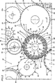
添付図面のうち図1を参照すると、1はフィルタ付きタバコを作る機械の全体を指す。 Referring to FIG. 1 of the accompanying drawings, 1 refers to the entire machine for making filtered tobacco.
機械1は、図1の表示面に対して垂直に伸びる相互に平行のそれぞれの軸の周りを回転可能なローラーの列を含むフィルタ付きタバコを製造する生産ライン2、及び生産ライン2の同じ側に配置されるそれぞれ3aおよび3bで示されるフィルタペーパー4をローラーへ供給する2つの同じ装置3、を含む。
The machine 1 comprises a production line 2 for producing a filtered cigarette comprising a row of rollers rotatable about respective mutually parallel axes extending perpendicular to the display surface of FIG. 1, and the same side of the production line 2 Two
生産ライン2は、インフィード区間5、ローリング区間6及びアウトフィード区間7から構成される。
The production line 2 includes an infeed
インフィード区間5は、ブロック9として略図的に示される移転手段によって従来の方法でブロック11として点線で示されるタバコ製造機のガーニチャ(garniture)区間10に接続される第一のインフィードローラー8を含む。ガーニチャ区間から2本の連続するシガレットロッドが出てくる。
The infeed
第一のインフィードローラー8は、ガーニチャュ区間10に沿って前進する2本のシガレットロッド間の距離に対応する予め決められたピッチpの間隔で配置される複数の吸引溝12を備えており、この中へ単長シガレットスティックの長さの二倍の個々のロッド13が送られる。
The first infeed roller 8 includes a plurality of
図1に示される通り左回りに回転すると、第一のローラー8は、第一のローラー8に対して接線方向に回転しかつ同様に上記の溝12と同じピッチpの間隔で配置され各々1本のロッド13を収める吸引溝15を備える第二のローラー14へロッド13を移転する。
When rotated counterclockwise as shown in FIG. 1, the first rollers 8 rotate in a tangential direction with respect to the first roller 8 and are similarly disposed at the same pitch p intervals as the
第二のローラー14が右回りに回転するとき、溝15を占めるロッド13は、軸方向に一直線の対の単長シガレットスティック17を生産するために、従来の実施態様のカッター装置16によって半分に横に切断される。
When the
第二のローラー14は、カッター装置16の下流の所定のポイントで、インフィード区間5の一部を形成しかつ上記の溝と同じピッチpの間隔で配置され、各々1対の軸方向に一直線にされる単長シガレットスティック17を収める溝19を備える従来のタイプの第三の引き離しローラー18に対して接線方向に回転する。
The
引き離しローラー18は、ローラー18が回転するとき各対の単長シガレットスティック17とかみ合うなど従来の実施態様の可動機構20を備え、倍長フィルタプラグ21の長さより僅かに長い距離だけスティックを分離する。
The pull-
対のシガレットスティック17は、左回りに回転するとき、引き離しローラー18から、右回りにセットされかつ上記の溝と同じピッチpの間隔で周縁に配置されるそれぞれの溝22を備える第四のローラー23へ移転される。引き離しローラー18によって軸方向に分離される1対のシガレットスティック17を取り上げる前に、第四のローラー23の各溝22は、このローラー23が引き離しローラー18に対して接線方向に回転するエリアの上流の一点で従来の供給装置21aから倍長フィルタプラグ21を受け取る。
When the pair of cigarette sticks 17 rotates counterclockwise, the fourth roller is provided with
各対の2本のシガレットスティック17は、倍長フィルタプラグ21をその間に挟んでこれと結合して、第四のローラー23の各溝22を占める3つの要素17、21、17(スティック-フィルタ-スティック)から成るそれぞれのアセンブリ24を生成する。
Each pair of two cigarette sticks 17 has a double-
Tで示される移転ステーションに到着すると、アセンブリ24は第四のローラー23から図1に示される通り左回りに回転するインフィード区間5の最終ローラー25へ移動する。ここから、アセンブリ24の列は、(順を追って説明するとおり)相互に平行に伸びかつアウトフィード区間7で合流する上部ブランチ26及び下部ブランチ27としてそれぞれ示される上記のローリング区間6の2つのブランチへ送られる。
Upon arrival at the transfer station indicated by T, the
より正確に言うと、図2に示される通り、最終ローラー25は、28で示される、最初に述べたピッチpの長さの二倍のピッチ2pの間隔で配置される1組の固定第一吸引溝、及び29で示される1組の可動第二吸引溝を備える。
More precisely, as shown in FIG. 2, the
固定第一溝28は、最終ローラー25の円筒形外面と一体的でかつこれからほぼ半径方向に伸びるそれぞれのブロック30の自由端によって与えられ、可動第二溝29はそれぞれのアーム31の自由端によって与えられる。アーム31は最終ローラー25の周縁の周りに配列されるそれぞれのシャフト32に取り付けられ、従来の実施態様のそれぞれのアクチュエータ手段(図には示されていない)によってローラー25の回転軸Aに平行に配置されるそれぞれの軸33上で旋回して2つの動作ポジションの間を交互に行き来する。
A fixed
ローラー25の全ての溝28及び29が上記のピッチpの間隔で配置されるように各可動第二溝29が2つの固定溝28の中間位置を占める第一の動作ポジションが、上記の移転ステーションTで取られる。
The first operating position in which each movable
第二の動作ポジションは、対応する軸Aの周りをローラー25が回転するときステーションTの下流の一点で取られる。
The second operating position is taken at a point downstream of the station T as the
上記のアーム31がそれぞれの軸33の周りで回される結果として、各対のアセンブリ24と次の順番の対のアセンブリ24との間の距離が単長フィルタペーパー4の幅にほぼ等しくなるように、第二溝29は、ローラー25の回転方向に関してすぐ上流の固定第一溝28に近づく。
As a result of the
動作中、最終ローラー25が移転ステーションTを越えて左回りに回転すると、可動溝29はそれぞれの軸33の周りを右回りに回り、その結果、アセンブリ24は、ステーションT1を通過する前に連続する狭い間隔の対となる。ステーションT1において、各固定溝28を占めるアセンブリ24は、上記の供給装置3aの一部を形成する吸引供給ローラー34からフィルタペーパー4を受け取る。
In operation, as the
また、材料の連続ストリップ36からフィルタペーパー4を分割するために、供給ローラー34と連動して動作するカッターローラー35がこの同じ装置3aの一部を構成する。
Also, a
T1で示されるステーションを通過するとき、フィルタペーパー4を受け取るアセンブリ24を収める各固定溝28と次の順番の可動溝29との間の距離は、単長フィルタペーパー4の幅と同じかこれより僅かに大きい。
When passing through the station indicated by T1, the distance between each
各固定溝28のブロック30は、それぞれのフィルタペーパー4が第一溝28を占めるアセンブリ24に貼られるとき、それぞれのフィルタペーパー4の自由端の残部となりかつフィルタペーパー4の糊付き面が対応するブロック30に接触するのを防ぐのに役立つ37で示される要素を備える。
The
さらに、第二溝29がそれぞれの軸33の周りで旋回運動した後、ローラー25の回転軸Aからのこの溝29の半径方向の距離は、ある量減少するので、それぞれのアセンブリ24とフィルタペーパー4を受け取るローラー34との間の接触を防ぐ。
Furthermore, after the
最終ローラー25は回転を続けるので、可動溝29を占めるアセンブリ24は、T2で示される移転ステーションで上記の上部ローリングブランチ26の一部を構成するインフィードローラー39の溝38へ引き渡され、固定溝28を占めすでに対応するフィルタペーパーを備えるアセンブリ24はT3で示される移転ステーションで下部ローリングブランチ27の一部を構成するインフィードローラー41の溝40へ引き渡される。
As the
3bで示される供給装置から紙4を受け取る上部ローリングブランチ26に沿って前進しかつインフィードローラー39の溝38を占めるアセンブリ24へのフィルタペーパー4の貼り付けに関しては、欧州特許第1 108 369号(EP−1 108 369)(十分な説明についてはこれを参照することができる)において開示されている。
Regarding the application of the
同様に、下部ローリングブランチ27の一部を構成するインフィードローラー41の溝40へ引き渡されるすでにフィルタペーパー4が貼られたアセンブリ24に関しても欧州特許第1 108 369号(EP−1 108 369)において説明されている。
Similarly, regarding the
上部ブランチ26及び下部ブランチ27によって回転され引き渡されるアセンブリ24はアウトフィード区間7の第一のローラーを構成するローラー42で合流する。
The
ローラー25が回転し続けると、上記の最後の移転ステーションT3の下流の所定の点で、アーム31は、第二溝29を最初の動作ポジションに戻して、第一の移転ステーションTに接近するとローラー25の固定溝28と可動溝29との間の均等のピッチpを回復するように、左回りに旋回する。
As the
最後に、本発明に従ったフィルタ付きタバコを作る機械の生産ライン2全体は冒頭に述べた先行技術の生産ラインに比べて最適化され単純化されていることが判るだろう。 Finally, it will be seen that the entire production line 2 of the machine for producing filtered tobacco according to the invention is optimized and simplified compared to the prior art production line mentioned at the beginning.
Claims (8)
フィルタ付きタバコ生産ライン(2)のインフィード区間(5)を構成するインフィードローラー(8)によって与えられる予め決められたピッチ(p)の間隔で配置されるそれぞれの溝(12)へ倍長シガレットロッド(13)を供給するステップと、
相互に軸方向に一直線になる対の単長シガレットスティック(17)を得るために前記倍長シガレットロッド(13)を前記インフィード区間(5)に沿った一点で横に切断するステップと、
各対の前記シガレットスティック(17)を前記インフィード区間(5)に沿って軸方向に引き離すステップと、
3つの軸方向に一直線になる要素から成るアセンブリ(24)を構成するように各対の単長スティック(17)の間に倍長フィルタプラグ(21)を配置するステップと、
前記インフィード区間(5)の最終ローラー(25)によって与えられる溝(28、29)へ前記予め決められたピッチ(p)で前記アセンブリ(24)を送るステップと、両方とも前記生産ライン(2)の同じ側に配置される2台の供給装置(3a、3b)によって各アセンブリ(24)にフィルタペーパー(4)を貼り付けるステップと、
前記インフィード区間(5)の前記最終ローラー(25)から離れて上部ブランチ(26)及び下部ブランチ(27)を含む前記生産ライン(2)のローリング区間(6)に沿って前記対応するフィルタペーパー(4)を前記アセンブリ(24)に貼ることによって前記倍長フィルタプラグ(21)を前記単長シガレットスティック(17)に接合するステップと、を含み、
前記溝(28、29)が交互に配置される第一溝(28)と第二溝(29)から成り、それによって1対のアセンブリ(24)と次の順番の対のアセンブリ(24)との間の距離が単長フィルタペーパー(4)の幅にほぼ等しくなるように前記第二溝(29)を隣接する前記第一溝(28)へ近づけることによって前記アセンブリ(24)が狭い間隔の対状に配列され、かつフィルタペーパー(4)が前記第一溝(28)を占める前記アセンブリ(24)に貼り付けられる、
前記最終インフィードローラー(25)の回転中に、実施されるステップを含むことを特徴とする、方法。A method of making a cigarette with a filter,
Double length to each groove (12) arranged at a predetermined pitch (p) interval provided by an infeed roller (8) constituting an infeed section (5) of a tobacco production line (2) with a filter Supplying a cigarette rod (13);
Cutting the double length cigarette rod (13) laterally at a point along the infeed section (5) to obtain a pair of single length cigarette sticks (17) that are axially aligned with each other;
Pulling each pair of cigarette sticks (17) axially along the infeed section (5);
Placing a double length filter plug (21) between each pair of single length sticks (17) to form an assembly (24) of three axially aligned elements;
Sending the assembly (24) at the predetermined pitch (p) to the grooves (28, 29) provided by the last roller (25) of the infeed section (5), both of which are in the production line (2 And affixing the filter paper (4) to each assembly (24) by two supply devices (3a, 3b) arranged on the same side of
The corresponding filter paper along the rolling section (6) of the production line (2) including the upper branch (26) and the lower branch (27) apart from the final roller (25) of the infeed section (5) Joining the double length filter plug (21) to the single length cigarette stick (17) by affixing (4) to the assembly (24);
The grooves (28, 29) are composed of a first groove (28) and a second groove (29), which are alternately arranged, whereby a pair of assemblies (24) and a next pair of assemblies (24) By moving the second groove (29) closer to the adjacent first groove (28) such that the distance between the two is substantially equal to the width of the single length filter paper (4), the assembly (24) is closely spaced. A filter paper (4) arranged in pairs and affixed to the assembly (24) occupying the first groove (28);
A method characterized in that it comprises the steps carried out during the rotation of the final infeed roller (25).
前記インフィード区間(5)が、タバコ製造機(1)のアウトフィード段階に連結されそれぞれの倍長シガレットロッド(13)を収めるのに役立つ複数の溝(12)を周縁に備える第一のインフィードローラー(8)と、
それぞれの溝(15)を設けかつそれぞれのカッター手段(16)を備えそれによって前記倍長ロッド(13)が前記第一のローラー(8)から取り上げられて軸方向に一直線になる対の単長シガレットスティック(17)を得るために横に切断されて、各対のスティック(17)がこのローラー(14)のそれぞれの溝(15)を占めるようにする第二のローラー(14)と、
各対の単長シガレットスティック(17)を相互に分離する第三の引き離しローラー(18)と、
前記第三の引き離しローラー(18)から受け取った1対のシガレットスティック(17)及び対応する供給装置(21a)から受け取った倍長フィルタプラグ(21)を収めるのに役立ちかつ軸方向に一直線になり対称的に配列される3つの要素すなわちスティック-フィルタ-スティックから成るアセンブリ(24)を作るそれぞれの溝(22)を設けた第四のローラー(23)と、
前記インフィード区間(5)の前記第四のローラー(23)から前記ローリング区間(6)の上部ブランチ(26)及び下部ブランチ(27)へ前記アセンブリ(24)を移転する最終ローラー(25)と、
各アセンブリ(24)にフィルタペーパー(4)を貼り付ける2台の供給装置(3a、3b)と、を組み込み、
前記最終ローラー(25)が交互に配置される第一溝及び第二溝(28、29)のセットを含み、
前記アセンブリ(24)が予め決められたピッチ(p)で前記第四のローラー(23)から取り上げられる1つの動作ポジションと、
各対のアセンブリ(24)と次の順番の対のアセンブリ(24)との間の距離が、1枚のフィルタペーパー(4)の幅にほぼ等しいように前記アセンブリ(24)が並んで狭い間隔の対に配列される別の動作ポジションと、の間で、各第二溝(29)が、それぞれの隣接する第一溝(28)に対して移動できる、
ことを特徴とする、機械。A machine for making a cigarette with a filter comprising an infeed section (5) and a rolling section (6),
The infeed section (5) is connected to the outfeed stage of the cigarette maker (1) and includes a plurality of grooves (12) at the periphery thereof for accommodating the respective double-length cigarette rods (13). A feed roller (8);
A pair of single lengths provided with respective grooves (15) and provided with respective cutter means (16) whereby the double-length rod (13) is taken up from the first roller (8) and is aligned in the axial direction A second roller (14) that is cut laterally to obtain a cigarette stick (17) so that each pair of sticks (17) occupies a respective groove (15) of the roller (14);
A third pulling roller (18) separating each pair of single length cigarette sticks (17) from each other;
Helps to accommodate a pair of cigarette sticks (17) received from the third pulling roller (18) and a double length filter plug (21) received from the corresponding feeding device (21a) and is aligned in the axial direction. A fourth roller (23) provided with a respective groove (22) creating an assembly (24) consisting of three elements arranged symmetrically, ie stick-filter-stick;
A final roller (25) for transferring the assembly (24) from the fourth roller (23) of the infeed section (5) to the upper branch (26) and the lower branch (27) of the rolling section (6); ,
Two feeding devices (3a, 3b) for attaching the filter paper (4) to each assembly (24),
Comprising a set of first and second grooves (28, 29) in which the final rollers (25) are arranged alternately;
One operating position in which the assembly (24) is picked up from the fourth roller (23) at a predetermined pitch (p);
The assemblies (24) are arranged side by side so that the distance between each pair of assemblies (24) and the next sequential pair of assemblies (24) is approximately equal to the width of one filter paper (4). Each second groove (29) can move relative to its respective adjacent first groove (28) between different operating positions arranged in pairs of
A machine characterized by that.
Applications Claiming Priority (2)
| Application Number | Priority Date | Filing Date | Title |
|---|---|---|---|
| IT000521A ITBO20040521A1 (en) | 2004-08-09 | 2004-08-09 | METHOD AND MACHINE FOR MAKING CIGARETTES WITH FILTER |
| PCT/IB2005/002308 WO2006016246A1 (en) | 2004-08-09 | 2005-07-25 | A method and a machine for making filter cigarettes |
Publications (3)
| Publication Number | Publication Date |
|---|---|
| JP2008508897A JP2008508897A (en) | 2008-03-27 |
| JP2008508897A5 JP2008508897A5 (en) | 2008-05-08 |
| JP4585003B2 true JP4585003B2 (en) | 2010-11-24 |
Family
ID=34956363
Family Applications (1)
| Application Number | Title | Priority Date | Filing Date |
|---|---|---|---|
| JP2007525372A Expired - Fee Related JP4585003B2 (en) | 2004-08-09 | 2005-07-25 | Method and machine for making cigarette with filter |
Country Status (7)
| Country | Link |
|---|---|
| EP (1) | EP1791446B1 (en) |
| JP (1) | JP4585003B2 (en) |
| CN (1) | CN100512692C (en) |
| AT (1) | ATE423478T1 (en) |
| DE (1) | DE602005012971D1 (en) |
| IT (1) | ITBO20040521A1 (en) |
| WO (1) | WO2006016246A1 (en) |
Families Citing this family (3)
| Publication number | Priority date | Publication date | Assignee | Title |
|---|---|---|---|---|
| DE102010002590B4 (en) | 2010-03-04 | 2013-07-04 | Hauni Maschinenbau Ag | Joining rod-shaped articles of the tobacco processing industry |
| PL3501300T3 (en) | 2017-12-19 | 2021-01-25 | G.D. S.P.A | Production line in the tobacco industry and method for inspecting it |
| CN114886148B (en) * | 2022-05-18 | 2023-08-22 | 红云红河烟草(集团)有限责任公司 | Improved method of tipping paper gluing equipment for improving total ventilation rate of filter cigarettes |
Family Cites Families (10)
| Publication number | Priority date | Publication date | Assignee | Title |
|---|---|---|---|---|
| US3010561A (en) * | 1957-12-26 | 1961-11-28 | Koerber & Co Kg | Filter mouthpiece cigarette making machines |
| US3712162A (en) * | 1969-07-15 | 1973-01-23 | Amf Inc | Filter plug offset |
| GB9513697D0 (en) * | 1995-07-05 | 1995-09-06 | Molins Plc | Cigarette manufacture |
| DE19631515A1 (en) * | 1996-08-03 | 1998-02-05 | Hauni Maschinenbau Ag | Method and device for combining smoking articles with glued connection sheets |
| IT1293302B1 (en) * | 1997-08-06 | 1999-02-16 | Gd Spa | METHOD OF ADVANCE OF BAR-SHAPED ITEMS. |
| IT1311424B1 (en) * | 1999-12-13 | 2002-03-12 | Gd Spa | METHOD AND MACHINE FOR THE CREATION OF CIGARETTES WITH FILTER. |
| DE10141703A1 (en) * | 2001-08-25 | 2003-03-06 | Hauni Maschinenbau Ag | Transfer device and method for transferring articles of the tobacco processing industry |
| ITBO20020412A1 (en) * | 2002-06-28 | 2003-12-29 | Gd Spa | METHOD FOR THE CREATION OF CIGARETTES WITH THE FILTER |
| ATE319336T1 (en) * | 2002-10-22 | 2006-03-15 | Hauni Maschinenbau Ag | METHOD AND DEVICE FOR COMBINING SMOKING ARTICLES |
| ATE327688T1 (en) * | 2003-04-11 | 2006-06-15 | Hauni Maschinenbau Ag | METHOD FOR ASSOCIATE SMOKING ARTICLE COMPONENTS |
-
2004
- 2004-08-09 IT IT000521A patent/ITBO20040521A1/en unknown
-
2005
- 2005-07-25 WO PCT/IB2005/002308 patent/WO2006016246A1/en active Application Filing
- 2005-07-25 DE DE602005012971T patent/DE602005012971D1/en active Active
- 2005-07-25 AT AT05761694T patent/ATE423478T1/en not_active IP Right Cessation
- 2005-07-25 EP EP05761694A patent/EP1791446B1/en not_active Not-in-force
- 2005-07-25 CN CNB2005800265209A patent/CN100512692C/en not_active Expired - Fee Related
- 2005-07-25 JP JP2007525372A patent/JP4585003B2/en not_active Expired - Fee Related
Also Published As
| Publication number | Publication date |
|---|---|
| EP1791446A1 (en) | 2007-06-06 |
| ITBO20040521A1 (en) | 2004-11-09 |
| JP2008508897A (en) | 2008-03-27 |
| DE602005012971D1 (en) | 2009-04-09 |
| CN100512692C (en) | 2009-07-15 |
| WO2006016246A1 (en) | 2006-02-16 |
| ATE423478T1 (en) | 2009-03-15 |
| CN1993062A (en) | 2007-07-04 |
| EP1791446B1 (en) | 2009-02-25 |
Similar Documents
| Publication | Publication Date | Title |
|---|---|---|
| JP7341206B2 (en) | Improvements in the assembly of smoking articles | |
| JP5442767B2 (en) | Apparatus and method for combining components for smoking articles | |
| EP1763306B1 (en) | Apparatus and method for the production of composite cigarette filters | |
| EP1787534B1 (en) | A machine for manufacturing composite filters | |
| AU2012264647A1 (en) | Modular apparatus for smoking article manufacture | |
| JP6048846B2 (en) | Method for producing cigarette with filter and filter mounting machine | |
| US10772351B2 (en) | Relating to smoking article assembly | |
| JP4585003B2 (en) | Method and machine for making cigarette with filter | |
| US20040200486A1 (en) | Method for combining smoking article components | |
| GB1603893A (en) | Method and machine for making recessed composite filter mouthpieces |
Legal Events
| Date | Code | Title | Description |
|---|---|---|---|
| A521 | Request for written amendment filed |
Free format text: JAPANESE INTERMEDIATE CODE: A523 Effective date: 20080318 |
|
| A621 | Written request for application examination |
Free format text: JAPANESE INTERMEDIATE CODE: A621 Effective date: 20080318 |
|
| TRDD | Decision of grant or rejection written | ||
| A01 | Written decision to grant a patent or to grant a registration (utility model) |
Free format text: JAPANESE INTERMEDIATE CODE: A01 Effective date: 20100803 |
|
| A01 | Written decision to grant a patent or to grant a registration (utility model) |
Free format text: JAPANESE INTERMEDIATE CODE: A01 |
|
| A61 | First payment of annual fees (during grant procedure) |
Free format text: JAPANESE INTERMEDIATE CODE: A61 Effective date: 20100902 |
|
| R150 | Certificate of patent or registration of utility model |
Free format text: JAPANESE INTERMEDIATE CODE: R150 |
|
| FPAY | Renewal fee payment (event date is renewal date of database) |
Free format text: PAYMENT UNTIL: 20130910 Year of fee payment: 3 |
|
| R250 | Receipt of annual fees |
Free format text: JAPANESE INTERMEDIATE CODE: R250 |
|
| LAPS | Cancellation because of no payment of annual fees |