EP1410158B1 - Power controlled electronic circuit - Google Patents
Power controlled electronic circuit Download PDFInfo
- Publication number
- EP1410158B1 EP1410158B1 EP02747347A EP02747347A EP1410158B1 EP 1410158 B1 EP1410158 B1 EP 1410158B1 EP 02747347 A EP02747347 A EP 02747347A EP 02747347 A EP02747347 A EP 02747347A EP 1410158 B1 EP1410158 B1 EP 1410158B1
- Authority
- EP
- European Patent Office
- Prior art keywords
- controller
- energy
- electronic circuit
- clock
- peripheral devices
- Prior art date
- Legal status (The legal status is an assumption and is not a legal conclusion. Google has not performed a legal analysis and makes no representation as to the accuracy of the status listed.)
- Expired - Lifetime
Links
Images


Classifications
-
- G—PHYSICS
- G06—COMPUTING OR CALCULATING; COUNTING
- G06F—ELECTRIC DIGITAL DATA PROCESSING
- G06F1/00—Details not covered by groups G06F3/00 - G06F13/00 and G06F21/00
- G06F1/26—Power supply means, e.g. regulation thereof
-
- G—PHYSICS
- G06—COMPUTING OR CALCULATING; COUNTING
- G06K—GRAPHICAL DATA READING; PRESENTATION OF DATA; RECORD CARRIERS; HANDLING RECORD CARRIERS
- G06K19/00—Record carriers for use with machines and with at least a part designed to carry digital markings
- G06K19/06—Record carriers for use with machines and with at least a part designed to carry digital markings characterised by the kind of the digital marking, e.g. shape, nature, code
- G06K19/067—Record carriers with conductive marks, printed circuits or semiconductor circuit elements, e.g. credit or identity cards also with resonating or responding marks without active components
- G06K19/07—Record carriers with conductive marks, printed circuits or semiconductor circuit elements, e.g. credit or identity cards also with resonating or responding marks without active components with integrated circuit chips
- G06K19/0701—Record carriers with conductive marks, printed circuits or semiconductor circuit elements, e.g. credit or identity cards also with resonating or responding marks without active components with integrated circuit chips at least one of the integrated circuit chips comprising an arrangement for power management
-
- G—PHYSICS
- G06—COMPUTING OR CALCULATING; COUNTING
- G06K—GRAPHICAL DATA READING; PRESENTATION OF DATA; RECORD CARRIERS; HANDLING RECORD CARRIERS
- G06K19/00—Record carriers for use with machines and with at least a part designed to carry digital markings
- G06K19/06—Record carriers for use with machines and with at least a part designed to carry digital markings characterised by the kind of the digital marking, e.g. shape, nature, code
- G06K19/067—Record carriers with conductive marks, printed circuits or semiconductor circuit elements, e.g. credit or identity cards also with resonating or responding marks without active components
- G06K19/07—Record carriers with conductive marks, printed circuits or semiconductor circuit elements, e.g. credit or identity cards also with resonating or responding marks without active components with integrated circuit chips
- G06K19/0723—Record carriers with conductive marks, printed circuits or semiconductor circuit elements, e.g. credit or identity cards also with resonating or responding marks without active components with integrated circuit chips the record carrier comprising an arrangement for non-contact communication, e.g. wireless communication circuits on transponder cards, non-contact smart cards or RFIDs
Definitions
- the present invention relates to electronic Circuits with a controller and in particular to the Control of the controller in these electronic circuits.
- CMOS complementary metal-oxide-semiconductor
- CMOS complementary metal-oxide-semiconductor
- DESoder AES symmetric encryption method
- cryptography controllers become, for example in smart cards, e.g. SIM cards or signature cards, for example, for payment with the mobile phone, for Home banking transactions or legally binding electronic Signatures used.
- cryptography controllers in computers or servers as a security IC used to perform an authentication, or to Encryption tasks to be able to take which, for example from the secure transmission of credit card numbers, the transmission of Emails secret contents and the secure cashless payments via the Internet can.
- cryptographic controllers must have a high computing power have to be the ones for the respective cryptographic Algorithm required calculations in appropriate Time to perform. For example, it would be for one User unreasonable, several minutes on an authentication check or a payment transaction wait have to. To achieve this high computing power, Known cryptographic controllers handle many of the things to do Arithmetic operations in parallel to the computational speed to increase.
- a potential design for a cryptography controller that On the one hand a high multi-functionality and on the other hand a high processing speed, consists of a composite of a central processing unit and one or more coprocessors working in parallel, as is the case with modern PCs, but also with modern ones Graphics cards is the case, and which via a bus system connected to each other.
- the coprocessors take over In this case complex arithmetic tasks, for example, certain Cryptographic algorithms or specific arithmetic operations are assigned, such.
- Terminals for Contact-based smart cards provide, for example, a maximum Current of a few mA, taking contactless applications and mobile applications, such.
- B. a SIM card in a cell phone the power may even be limited to less than 10 mA can. Consequently, the computational speed of coprocessors limited by the available energy.
- the clock frequency with which the CPU and the crypto-coprocessors are subject to restrictions by the Energy available as with the implementation of the controller chip in CMOS technology the power consumption of the Clock frequency or the switching frequency of the MOSFETs depends.
- the object of the present invention is to provide a electronic circuit and a method for controlling a to create electronic circuit, so that at the same to Available energy the computing power is increased.
- An electronic circuit comprises a Controller for processing a processor task and a Energy determination device for determining the for the controller available energy.
- a control device the electronic circuit controls the controller from the energy available to the controller.
- An inventive method for controlling an electronic Circuit which is a controller for processing a Processor task includes determining the for the Controller available energy as well as controlling of the controller depending on which is available for the controller standing energy.
- the present invention is based on the finding that by determining which for the controller, e.g. a cryptography controller, available energy an optimization the computing time of an operation can be achieved by optimally determining the energy, for example relevant, i. for a present processor task mainly required coprocessors or other peripheral devices or the CPU of the controller is distributed. Even though for this purpose, the electronic circuit energy determination device or an energy meter is added, causing The complexity of the same can be increased by the the best possible use of energy on the one hand an improvement the computing power with constant circuit complexity and on the other hand, a reduced circuit complexity be achieved with constant computing power.
- the controller e.g. a cryptography controller
- the controller of the controller depending on the available for the controller standing energy performed by the controller clock, with which the controller is operated is raised, if more Energy is available, and is reduced if less Energy is available.
- the Controller clock according to the determined available energy tracked to make the best possible use of the available to achieve standing energy.
- the controller can do this be carried out that on the one hand to carry out the Processor task required computing time is minimized and In addition, the available energy is sufficient.
- the controller is controlled so that on the one hand to the Available energy to process the processor task is sufficient by the controller, and on the other hand, the respective Peripheral device or the respective coprocessor maximum amount of energy to perform the arithmetic task is assigned.
- the Available energy between a peripheral device and a CPU of the controller divided by, for example because of the few of the CPU during one RSA encryption work to be done, the CPU low clocked and the peripheral device, i. the responsible person Coprocessor for modular multiplications, high clocked becomes.
- the available energy primarily between two peripheral devices split by, for example, during an elliptic-curve encryption of this mainly provided coprocessor clocked high and a for Secondary calculations required coprocessor low clocked becomes. Overall, this results in a reduction of the required Calculation time with optimal energy utilization.
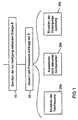
- FIG. 1 the invention Energy management and the benefits that result from it, described.
- Figs. 2 and 3 is then a Embodiment of an electronic circuit according to the present invention described.
- FIG. 4 is finally the application of the energy control of the invention in the case of contactless applications.
- the available energy E can vary for different reasons.
- the electronic circuit for chip cards for contact terminals can the energy available, for example, from Terminal to terminal or due to contact fluctuations between the contact terminal and the electronic Circuit vary. In contactless applications, the depends on Available energy E from the distance of a contact terminal terminal interface the chip card from the contact terminal from, as will be explained with reference to FIG. 4 in more detail becomes.
- the energy available due to the increasing discharge of the battery For mobile applications, such as B. in mobile phones, laptops or the like, the energy available due to the increasing discharge of the battery.
- the determination itself can be made in different ways or be carried out by means of different devices, taking various parameters as a measure of the available standing energy can be used, such. Legs Input voltage or a coupled current.
- a control of Controllers of the electronic circuit depending on the Available energy E which is determined in step 10 has been.
- the controller of the controller depends be carried out by the energy E in different ways in Fig. 1, only by way of example three possibilities 20a, 20b and 20c are shown.
- a first possibility 20a to control the controller consists in setting the Clock frequency of the controller depending on the available standing energy E. By changing the clock frequency is the Switching frequency of the switching elements forming the controller changed, for example, when implementing the controller in CMOS technology, a change in power consumption or the power consumption results.
- the clock frequency must be lower be adjusted while if more energy available stands, the clock frequency and thus the computing speed can be increased.
- the controller consists of several components can, as it referring will be explained in more detail in Fig. 2, the clock frequency for each component, e.g. a CPU or a peripheral device, such as. a coprocessor, individually adjusted become.
- the clock frequencies of the various Components can use the available energy E be fully exploited, or completely on all components required for the current processor task be distributed.
- the distribution of available Energy to the various components by adjusting The different clock frequencies may be in the sense of optimization the computing time of the processor task performed which is due to the computing time both by the maximum Exploiting the available energy as well through the simultaneous optimal distribution of energy the individual components is minimized.
- a second possibility 20b for controlling the controller exists in turning off controller components used for the current processor task is not relevant. These non-relevant controller components, for example by additional switching elements, e.g. FETs with low Leakage current, disconnected from the supply voltage to the same into a sleep mode.
- additional switching elements e.g. FETs with low Leakage current
- Another possibility 20c for controlling the controller consists in adjusting the supply voltage of the entire Controllers or individual components of the controller.
- the supply voltage could, for example, in the case that the available energy has a specific Threshold below, set to a lower value where the reliability of the controller operation less but still sufficient.
- the supply voltage for analog components of the electronic Circuit could be changed, such. B. for the analog Part of a contact terminal interface of the electronic Circuit.
- a main advantage of the above with reference to FIG. 1 described energy control is that in comparison to conventional electronic circuits used for a certain minimum supply energy are designed determines the available energy E and then is completely used up to operate the controller. In this way, also the minimum supply energy Exceeding share of available energy used for faster processing of the processor task become. While consequently in conventional electronic Circuits special peripheral devices that enhance the overall performance of the system, only operated in fixed predetermined multiples of a CPU clock be, and this is only possible if the Available energy can be sufficient through the Energy control according to the invention at excess available standing power individual peripheral devices higher be clocked so that the available Energy as possible, i. essentially completely, exploited is.
- the determined available energy optimal in terms of optimizing the computing time distributed to the relevant coprocessors so that the available energy is not just completely used up but also optimally exploited or used, whereby the computing speed of the controller at gleichereastender Energy increased and thus the user latency can be reduced at the terminal.
- an electronic will be hereinafter referred to Circuit according to an embodiment of the present invention Invention described.
- Circuit according to this embodiment comprises the electronic circuit a cryptography processor and is arranged on a chip card for the application suitable for contactless terminals.
- the electronic circuit comprises a contact terminal terminal interface 100 and a cryptography processor, which consists of a CPU 110 and a peripheral device 120, such as a crypto-coprocessor, an RNA generator or a UART module, wherein in For ease of illustration, a crypto-coprocessor is assumed below as the peripheral device.
- the CPU 110 and the crypto-coprocessor 120 are each assigned a clock multiplier 130 and 140, respectively, which output a clock signal clock CPU or clock crypto to the CPU 110 and the crypto-coprocessor 120, and clock generators can be used instead of clock multipliers.
- the contact terminal interface 100 which is arranged to convert electromagnetic energy 105 from a contact terminal (not shown) into electrical energy for powering the electronic circuit, and consists of, for example, an antenna, a rectifier, and a low pass filter, supplies the supply power to both clock multipliers 130 and 140 as well as an energy meter 150.
- the energy meter 150 outputs control signals VC CPU and VC Krypto to the two clock multipliers 130 and 140, depending on the power available from the contact terminal interface 100, to control the clock frequencies of the clock signals of the clock multipliers 130 and 140 that are connected to the clocks CPU 110 and coprocessor 120 are output.
- the cryptography processor consisting of the CPU 110 and the crypto-coprocessor 120 is, for example, for processing certain processor tasks, such as one Encryption, decryption, authentication or signature based on the DES standard, the AES method, the RSA algorithm or the elliptic curve method.
- processor tasks such as one Encryption, decryption, authentication or signature based on the DES standard, the AES method, the RSA algorithm or the elliptic curve method.
- the Cryptocoprocessor 120 is in turn to perform a particular Arithmetic task provided, such as a modular or arithmetic addition, multiplication, exponentiation or inversions, a hash value calculation.
- a peripheral device 120 the same be an RNA generator, UART or sensor.
- the electrical energy that the contactlost terminal interface 100 extracts from the electromagnetic energy 105 is determined by the energy meter 150 and distributed to the CPU 110 and the crypto-coprocessor 120 by the clock multipliers 130 and 140 such that the CPU is supplied with the least possible energy, while the crypto-coprocessor 120, the maximum possible energy is provided.
- the distribution of the available energy to the CPU 110 and the crypto-coprocessor 120 the fact is exploited in the present case that changing the clock frequencies of the clock signals clock CPU and clock crypto of these components also determines the energy consumption of these components.
- the energy consumption depends on the switching frequency of the individual MOSFETs. Consequently, full utilization of the available energy is achieved by the fastest possible clocking of the crypto-coprocessor 120, which enables a high computing speed.
- the clock multipliers 130 and 140 are designed such that they output clock signals clock CPU and clock crypto with the same control signal whose clock frequencies differ by a fixed multiple n.
- the energy meter 150 it is also possible for the energy meter 150 to output differently high clock signals VC CPU and VC Krypto to the clock multipliers 130 and 140.
- the energy meter 150 is formed either as a regulator which converts the received supply energy from the contact terminal interface 100 into a voltage signal, as determined by a circuit design, such as, e.g.
- a linear regulator or includes an A / D converter to convert the supply energy into digital control signals VC CPU and VC Krypto .
- digital control signals a look-up table can be provided in which for certain supply energy ranges control signals VC CPU and VC Krypto are stored which ensure an optimum computing time of the cryptography processor for the respective supply energy range.
- the clock multipliers 130 and 140 of Fig. 2 are formed in the form of PLLs which allow clock frequency multiplication of an input frequency by rational multiples n / m.
- the input frequency is predetermined, for example, by a clock signal generated by the contact terminal interface 100.
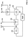
- a block diagram of the clock multipliers 130 and 140 is shown in FIG.
- each clock multiplier comprises an input IN 200 to which the clock signal of the input frequency f in is applied, inputs INn and INm at which the value of the counter n and the denominator m of the rational multiple between the input frequencies f in and Output frequency f out is applied, and an output OUT, at which a clock signal with the clock frequency f out is output.
- the circuit comprises, in addition to a frequency divider 220, a PLL consisting of a voltage-controlled oscillator VCO 230, a frequency divider 240, an XOR circuit 250 and a regulator 260.
- One input of the frequency divider 220 is connected to the input IN 200 and another input to the input INm 210.
- the frequency divider 220 outputs an output signal of the frequency f in / m, the output being connected to an input of the XOR circuit 250.
- Another input of the XOR circuit 250 is connected to an output of the frequency divider 240, whose two inputs are connected to the input INn 205 and an output of the VCO 230, respectively.
- An input of the VCO 230 is connected through the regulator 260 to an output of the XOR circuit 250.
- the output of the VCO 230 is also connected to the output OUT 215.
- the control inputs INn and Inm which are controlled by the control signals VC CPU and VC crypto (see FIG. 2), can be used to set the divider ratios n and m (n, m ⁇ 1,2,3 ...), with which the frequency divider 220 and 240, the frequencies of the input clock signal at the input 200 and the output signal of the oscillator 230 share.
- the voltage controlled oscillator 230 is readjusted by the XOR circuit 250 in cooperation with the controller 260 in order to achieve the desired divider ratio between the input clock signal and the output clock signal. Consequently, the clock signal applied to the output OUT has the desired frequency f out .
- Fig. 4 shows schematically a chip card on which the electronic circuit of Fig. 2 is arranged, in three positions 300a, 300b and 300c relative to a contact terminal terminal 310 emitting an electromagnetic radiation 320 of a certain frequency.
- the various positions 300a-300c are at different exemplary distances, ie, 10 cm, 7 cm, and 5 cm, to the contactless terminal 310 Contactless terminal interface (see Fig.
- the electronic circuit depends on the distance d of the smart card from the contact terminal 310, at the various positions 300a, 300b and 300c depending on the distance of the smart card be set by the contactless terminal 310 higher or lower clock frequency f 1 , f 2 and f 3 for the controller of the electronic circuit. If the card is further away from the terminal 310, less power is available to the electronic circuitry, so the clock frequency must be lower. If the card comes closer to the terminal 310, more energy is available, so that the controller can be clocked at a higher clock frequency. In this way, the clock frequency is always adapted to the available energy, so that, when more energy is available, a lower computing time is made possible.
- a fixed power consumption such as a fixed clock frequency, for example, which corresponds to a certain maximum distance of the chip card from the terminal 310 and was a compromise of the widest possible range of distances and the highest possible computing power was. Consequently, operation of the cryptographic processor was only possible within this range, with the excess energy being dissipated at shorter intervals.
- a cryptography processor of a CPU and a peripheral device or a crypto-coprocessor In The more common cases become a cryptography processor however, more peripheral devices and crypto-coprocessors consist.
- the available standing energy such as, for example, the coprocessors be distributed, that a minimum computing time at maximum Energy utilization is achieved. This is achieved by at the distribution of available energy through the energy meter is determined on the coprocessors and the CPU additionally the current processor task and the different computing tasks of coprocessors and the associated tasks remaining peripheral devices taken into account become. The available energy will then always used for that or those coprocessors, in the application or the processor task on most claimed.
- Authentication becomes, for example, the crypto-coprocessor the maximum possible energy allocated during the CPU and the remaining coprocessors only a minimal proportion the available energy is allocated. On Similarly, the available energy goes through the fastest possible timing, for example in an encryption task on the DES module and in the calculation of the hash value to the hash module. For the current one Processor task non-relevant coprocessors can even completely switched off or put into a sleep mode be separated by the same from the supply voltage to avoid leakage currents.
- the optimal distribution of available energy among multiple coprocessors can be achieved by assigning a clock multiplier to each coprocessor, just as in FIG. 2 the clock multiplier 140 is assigned to the crypto-coprocessor 120.
- the CPU may be operated at the clock frequency f CPU
- the coprocessors that are not currently required in the processor task may be disabled or can be operated at the frequency f CPU
- only the crypto-coprocessor that is required in the application is clocked at a higher clock frequency, which is set so that the available energy is used up as completely as possible.
- optimization of computational speed and maximum power utilization is achieved by increasing or decreasing the clock frequency of the coprocessor currently being used primarily by the processor task, clocking it at the maximum possible clock frequency, and allowing the remaining available energy to operate the remaining required components is sufficient.
- each one optimized set of clock frequencies for the crypto-coprocessors is stored.
- Each set of clock frequencies would be the allocated energy available substantially distribute to those crypto-coprocessors whose associated Computing tasks in the associated application needed become.
- the clock frequencies within each set determined so that the available energy, of which this sentence is assigned, essentially completely used up becomes.
- the electronic circuit on both a circuit board can be arranged as well as integrated in a chip.
- the controller can either consist of individual components, which are arranged on a circuit board, or in be integrated into a single chip.
- the present invention relates to a contactless application has been described, is the present invention also on applications at contact terminals or on mobile Applications applicable.
- the contact terminal interface could of Fig. 2 by a simple contact be replaced.
Landscapes
- Engineering & Computer Science (AREA)
- Computer Hardware Design (AREA)
- Microelectronics & Electronic Packaging (AREA)
- Theoretical Computer Science (AREA)
- Physics & Mathematics (AREA)
- General Physics & Mathematics (AREA)
- Computer Networks & Wireless Communication (AREA)
- General Engineering & Computer Science (AREA)
- Power Sources (AREA)
- Executing Machine-Instructions (AREA)
- Control Of Electrical Variables (AREA)
- Feedback Control In General (AREA)
- Microcomputers (AREA)
- Electronic Switches (AREA)
- Electrophonic Musical Instruments (AREA)
- Oscillators With Electromechanical Resonators (AREA)
- Ignition Installations For Internal Combustion Engines (AREA)
- Electrical Discharge Machining, Electrochemical Machining, And Combined Machining (AREA)
Abstract
Description
Die vorliegende Erfindung bezieht sich auf elektronische Schaltungen mit einem Controller und insbesondere auf die Steuerung des Controllers bei diesen elektronischen Schaltungen.The present invention relates to electronic Circuits with a controller and in particular to the Control of the controller in these electronic circuits.
Mit der zunehmenden Verbreitung des bargeldlosen Zahlungsverkehrs, der elektronischen Datenübertragung über öffentliche Netze und dem Austausch von Kreditkartennummern über öffentliche Netze steigt der Bedarf nach Kryptographiealgorithmen, um digitale Signaturen, Authentifikationen oder Verschlüsselungsaufgaben durchführen zu können. Bekannte Kryptographiealgorithmen umfassen asymmetrische Verschlüsselungsalgorithmen, wie z.B. den RSA-Algorithmus oder auf elliptischen Kurven basierende Verfahren, oder symmetrische Verschlüsselungsverfahren, wie z.B. Verschlüsselungsverfahren nach dem DESoder AES-Standard.With the increasing spread of cashless payments, electronic data transmission via public Networks and the exchange of credit card numbers via public Networks, the need for cryptographic algorithms increases, to digital signatures, authentications or encryption tasks to carry out. Known cryptographic algorithms include asymmetric encryption algorithms, such as. the RSA algorithm or on elliptic curves based methods, or symmetric encryption methods, such as. Encryption method according to the DESoder AES standard.
Um die durch die Kryptographiealgorithmen vorgeschriebenen Berechnungen im Alltag in akzeptabler Geschwindigkeit ausführen zu können, werden eigens vorgesehene Kryptographiecontroller eingesetzt. Solche Kryptographiecontroller werden beispielsweise in Chipkarten, wie z.B. SIM-Karten oder Signaturkarten, beispielsweise zur Zahlung mit dem Mobiltelephon, für Homebankingtransaktionen oder rechtsverbindliche elektronische Unterschriften verwendet. Alternativ werden Kryptographiecontroller in Computern oder Servern als Sicherheits-IC verwendet, um eine Authentifikation durchzuführen, oder um Verschlüsselungsaufgaben übernehmen zu können, welche beispielsweise aus der sicheren Übermittlung von Kreditkartennummern, der Übermittlung von Emails geheimen Inhalts und dem sicheren bargeldlosen Zahlungsverkehr über das Internet bestehen können. To those prescribed by the cryptographic algorithms Perform calculations in everyday life at an acceptable speed to be able to be specially designed cryptography controller used. Such cryptography controllers become, for example in smart cards, e.g. SIM cards or signature cards, for example, for payment with the mobile phone, for Home banking transactions or legally binding electronic Signatures used. Alternatively, cryptography controllers in computers or servers as a security IC used to perform an authentication, or to Encryption tasks to be able to take which, for example from the secure transmission of credit card numbers, the transmission of Emails secret contents and the secure cashless payments via the Internet can.
Es werden hohe Anforderungen an die Kryptographiecontroller gestellt, damit dieselben den hohen Ansprüchen der Benutzer genügen und sich auf dem Markt etablieren können. Um eine hohe algorithmische Sicherheit gegenüber Fremdattacken gewährleisten zu können, müssen Kryptrographiecontroller beispielsweise eine beachtliche Rechenleistung zur Verfügung stellen. Der Grund hierfür besteht darin, daß die Sicherheit kryptographischer Algorithmen, wie z.B. des bekannten RSA-Algorithmus, im allgemeinen entscheidend von der Bitlänge des verwendeten Schlüssels abhängt, und daß folglich die Kryptographiecontroller, die die entsprechenden Kryptographiealgorithmen ausführen, in der Lage sein müssen, mit Zahlen möglichst großer Länge umzugehen. Bei dem RSA-Algorithmus haben sich beispielsweise Schlüsselbitlängen von 1024 Bits oder bis zu 2048 Bits durchgesetzt, wobei im Vergleich hierzu derzeitige Allzweckprozessoren mit 8-Bit-, 32-Bit- oder maximal 64-Bit-Zahlen arbeiten.There are high demands on the cryptography controller to meet the high demands of users suffice and become established in the market. To a high ensure algorithmic security against external attacks To be able to cryptography controller, for example to provide a considerable computing power. The reason for this is that the security of cryptographic Algorithms, such as the well-known RSA algorithm, generally of the bit length of the used, and that consequently the cryptography controllers, the corresponding cryptographic algorithms To be able to perform with numbers as possible to handle large length. At the RSA algorithm have For example, key bit lengths of 1024 bits or until enforced to 2048 bits, compared to current ones General-purpose processors with 8-bit, 32-bit or 64-bit maximum numbers work.
Weiterhin müssen Kryptographiecontroller eine hohe Rechenleistung aufweisen, um die für den jeweiligen kryptographischen Algorithmus erforderlichen Berechnungen in angemessener Zeit durchführen zu können. So wäre es beispielsweise für einen Benutzer unzumutbar, mehrere Minuten auf eine Authentifikationsüberprüfung oder eine Zahlungstransaktion warten zu müssen. Um diese hohen Rechenleistungen erzielen zu können, verarbeiten bekannte Kryptographiecontroller viele der durchzuführenden Rechenoperationen parallel, um die Rechengeschwindigkeit zu erhöhen.Furthermore, cryptographic controllers must have a high computing power have to be the ones for the respective cryptographic Algorithm required calculations in appropriate Time to perform. For example, it would be for one User unreasonable, several minutes on an authentication check or a payment transaction wait have to. To achieve this high computing power, Known cryptographic controllers handle many of the things to do Arithmetic operations in parallel to the computational speed to increase.
Bei der Verwendung von Kryptographiecontrollern in Chipkarten, wie z.B. SIM-Karten oder Signaturkarten, ergibt sich ein zusätzliches Problem daraus, daß dieselben als Massenprodukt preisgünstig herstellbar sein müssen. Obwohl dieselben also rechenaufwendige Algorithmen in möglichst kurzer Zeit abarbeiten müssen, darf umgekehrt die elektronische Schaltung nicht zu aufwendig und damit teuer sein. When using cryptography controllers in smart cards, such as. SIM cards or signature cards, this results additional problem with them being mass-produced must be inexpensive to produce. Although the same execute computation-intensive algorithms in as short a time as possible must, conversely, the electronic circuit not too expensive and therefore expensive.
Ein weiteres Problem bei dem Entwurf von Kryptographiecontrollern ergibt sich aus der Koexistenz vieler allgemein üblicher Kryptographiealgorithmen. In dem Fall einer Chipkarte wird sich beispielsweise derjenige Kryptographiecontroller auf dem Markt durchsetzen, der zur Durchführung der meisten üblichen Kryptographiealgorithmen fähig ist, und der folglich eine breite Einsatzfähigkeit und eine hohe Anwenderfreundlichkeit aufweist. Ein solcher "multifunktionaler" Kryptographiecontroller verhindert beispielsweise, daß ein Benutzer mehrere Chipkarten herumtragen muß, von denen jede für eine spezielle Anwendung bzw. für ein spezielles Kryptographieverfahren vorgesehen ist. Ein solcher multifunktionaler Kryptographiecontroller muß jedoch aufgrund der vielseitigen Verwendung zu einer Vielzahl von Rechenoperationen in der Lage sein, die von den vielen kryptographischen Algorithmen verwendet werden, was zu einer Zunahme der Komplexität oder einer Reduzierung der Geschwindigkeit der elektronischen Schaltung führt.Another problem with the design of cryptographic controllers results from the coexistence of many commonplace Cryptographic algorithms. In the case of a smart card For example, the cryptography controller will become one to enforce in the market, to carry out the most conventional cryptographic algorithms, and therefore a broad operational capability and a high user friendliness having. Such a "multifunctional" cryptography controller prevents, for example, a user several chip cards carry around, each of which for a special application or for a special cryptography method is provided. Such a multifunctional cryptography controller However, due to the versatile use capable of a variety of arithmetic operations which is used by the many cryptographic algorithms be, resulting in an increase in complexity or one Reduce the speed of the electronic circuit leads.
Ein möglicher Entwurf für einen Kryptographiecontroller, der einerseits eine hohe Multifunktionalität und andererseits eine hohe Verarbeitungsgeschwindigkeit aufweist, besteht aus einem Verbund aus einer zentralen Verarbeitungseinheit und einem oder mehreren Coprozessoren, welche parallel arbeiten, wie es beispielsweise bei modernen PCs aber auch bei modernen Graphikkarten der Fall ist, und welche über ein Bussystem miteinander verbunden sind. Die Coprozessoren übernehmen hierbei aufwendige Rechenaufgaben, die beispielsweise bestimmten Kryptographiealgorithmen oder bestimmten Rechenoperationen zugeordnet sind, wie z. B. eine modulare oder arithmetische Multiplikation.A potential design for a cryptography controller that On the one hand a high multi-functionality and on the other hand a high processing speed, consists of a composite of a central processing unit and one or more coprocessors working in parallel, as is the case with modern PCs, but also with modern ones Graphics cards is the case, and which via a bus system connected to each other. The coprocessors take over In this case complex arithmetic tasks, for example, certain Cryptographic algorithms or specific arithmetic operations are assigned, such. B. a modular or arithmetic Multiplication.
Ein zusätzliches Problem, dem sich Kryptographiecontroller stellen müssen, besteht nun darin, daß denselben lediglich eine begrenzte Energie zur Verfügung steht. Terminals für kontaktbehaftete Chipkarten liefern beispielsweise einen maximalen Strom von wenigen mA, wobei bei kontaktlosen Anwendungen und mobilen Anwendungen, wie z. B. einer SIM-Karte in einem Handy, der Strom sogar auf unter 10 mA begrenzt sein kann. Folglich ist die Rechengeschwindigkeit der Coprozessoren durch die zur Verfügung stehende Energie begrenzt. Auch die Taktfrequenz mit der die CPU und die Kryptocoprozessoren getaktet werden, unterliegt Einschränkungen durch die zur Verfügung stehende Energie, da bei Implementierung des Controllerchips in CMOS-Technologie der Stromverbrauch von der Taktfrequenz bzw. der Umschaltfrequenz der MOSFETs abhängt.An additional issue for cryptography controllers The problem is that they must be made only by limited energy is available. Terminals for Contact-based smart cards provide, for example, a maximum Current of a few mA, taking contactless applications and mobile applications, such. B. a SIM card in a cell phone, the power may even be limited to less than 10 mA can. Consequently, the computational speed of coprocessors limited by the available energy. Also the clock frequency with which the CPU and the crypto-coprocessors are subject to restrictions by the Energy available, as with the implementation of the controller chip in CMOS technology the power consumption of the Clock frequency or the switching frequency of the MOSFETs depends.
Den Problemen der geringen und bei kontaktlosen und mobilen Anwendungen sogar schwankenden bzw. abnehmenden zur Verfügung stehenden Energie wird bei herkömmlichen Kryptographiecontrollern lediglich dadurch begegnet, daß dieselben für eine bestimmte minimale Energieversorgung ausgelegt werden. Der gesamte Kryptographiecontroller, d. h. die CPU und die Kryptocoprozessoren, werden mit festen Taktfrequenzen derart getaktet, daß die für die eingestellten Taktfrequenzen notwendige Energie der minimalen Energie entspricht. Folglich ist ein Betrieb der Schaltung nur dann möglich, falls die zur Verfügung stehende Energie ausreicht, d. h. gleich oder größer der minimalen Energie ist. Aufgrund der festen Taktung der Coprozessoren ist die zum Betrieb des Kryptographiecontrollers notwendige Energie zudem unabhängig von der Kryptographiecontrolleraufgabe, so daß beispielsweise für aufwendige RSA-Kryptographieanwendungen ebenso viel Energie erforderlich ist wie für weniger aufwendige, auf elliptischen Kurven basierende Berechnungen. Darüber hinaus geht in dem Fall, daß die zur Verfügung stehende Energie die zum Betrieb des Kryptographiecontrollers erforderliche Energie überschreitet, die zusätzliche zur Verfügung stehende Energie verloren und bleibt ungenutzt. WO 00/07141A schlägt vor, das nutzlose Verlorengehen überschüssiger Leistung bei Kontaktloschipkarten dadurch zu verhindern, daß ein Taktsignalgenerator durch ein Steuersignal zu einer Änderung der Frequenz des Taktsignals angesteuert wird, das zu dem Überschußstrom proportional ist.The problems of low and non-contact and mobile Applications even fluctuating or decreasing available standing energy is used in conventional cryptography controllers only by the fact that the same for a certain minimum energy supply will be designed. Of the entire cryptography controller, d. H. the CPU and the crypto-coprocessors, are clocked with fixed clock frequencies such that necessary for the set clock frequencies Energy of minimum energy equals. Consequently, it is operation of the circuit only possible if the to Available energy is sufficient, d. H. equal or greater the minimum energy is. Due to the fixed timing the coprocessor is to operate the cryptography controller necessary energy also independent of the cryptography controller task, so that, for example, for consuming RSA cryptography applications require just as much energy is like for less elaborate, on elliptical curves based calculations. Moreover, in the case that the energy available to operate the cryptography controller exceeds required energy that lost extra available energy and remains unused. WO 00 / 07141A suggests the useless loss of surplus To prevent power in Kontaktloschipkarten thereby, that a clock signal generator by a Control signal is driven to a change in the frequency of the clock signal, which is proportional to the excess current.
Für Chipkarten- und Security-IC-Hersteller wären Kryptographiecontroller mit einer besseren Energieausnutzung von enormer Bedeutung, da hierdurch einerseits die Rechengeschwindigkeit und somit die Wartezeiten an den Terminals und die Anwenderfreundlichkeit erhöht und andererseits bei gleicher Rechengeschwindigkeit die Schaltungskomplexität und damit die Kosten des Controllers, was insbesondere bei Massenprodukten vorteilhaft ist, reduziert werden könnten.For smart card and security IC manufacturers would be cryptography controllers with a better energy utilization of enormous Meaning, because on the one hand the computing speed and thus the waiting times at the terminals and the user-friendliness increased and on the other hand at the same computing speed the circuit complexity and thus the Cost of the controller, which is especially true for mass products is advantageous, could be reduced.
Die Aufgabe der vorliegenden Erfindung besteht darin, eine elektronische Schaltung und ein Verfahren zum Steuern einer elektronischen Schaltung zu schaffen, so daß bei gleicher zur Verfügung stehender Energie die Rechenleistung erhöht ist.The object of the present invention is to provide a electronic circuit and a method for controlling a to create electronic circuit, so that at the same to Available energy the computing power is increased.
Diese Aufgabe wird durch eine elektronische Schaltung gemäß Anspruch 1 und ein Verfahren gemäß Anspruch 13 gelöst.This task is performed by an electronic circuit according to Claim 1 and a method according to claim 13 solved.
Eine erfindungsgemäße elektronische Schaltung umfaßt einen Controller zum Verarbeiten einer Prozessoraufgabe sowie eine Energiebestimmungseinrichtung zum Ermitteln der für den Controller zur Verfügung stehenden Energie. Eine Steuereinrichtung der elektronischen Schaltung steuert den Controller abhängig von der für den Controller zur Verfügung stehenden Energie.An electronic circuit according to the invention comprises a Controller for processing a processor task and a Energy determination device for determining the for the controller available energy. A control device the electronic circuit controls the controller from the energy available to the controller.
Ein erfindungsgemäßes Verfahren zum Steuern einer elektronischen Schaltung, die einen Controller zum Verarbeiten einer Prozessoraufgabe aufweist, umfaßt das Ermitteln der für den Controller zur Verfügung stehenden Energie sowie das Steuern des Controllers abhängig von der für den Controller zur Verfügung stehenden Energie.An inventive method for controlling an electronic Circuit, which is a controller for processing a Processor task includes determining the for the Controller available energy as well as controlling of the controller depending on which is available for the controller standing energy.
Der vorliegenden Erfindung liegt die Erkenntnis zugrunde, daß durch Ermittlung der für den Controller, wie z.B. einen Kryptographiecontroller, zur Verfügung stehenden Energie eine Optimierung der Rechenzeit einer Operation erzielt werden kann, indem die ermittelte Energie beispielsweise optimal auf die maßgeblichen, d.h. die für eine vorliegende Prozessoraufgabe vorwiegend benötigten, Coprozessoren oder andere Peripherievorrichtungen oder die CPU des Controllers verteilt wird. Obwohl hierzu der elektronischen Schaltung eine Energiebestimmungseinrichtung bzw. ein Energiemesser hinzugefügt wird, wodurch die Komplexität derselben erhöht wird, kann durch die bestmögliche Ausnutzung der Energie einerseits eine Verbesserung der Rechenleistung bei gleichbleibender Schaltungskomplexität und andererseits eine reduzierte Schaltungskomplexität bei gleichbleibender Rechenleistung erzielt werden.The present invention is based on the finding that by determining which for the controller, e.g. a cryptography controller, available energy an optimization the computing time of an operation can be achieved by optimally determining the energy, for example relevant, i. for a present processor task mainly required coprocessors or other peripheral devices or the CPU of the controller is distributed. Even though For this purpose, the electronic circuit energy determination device or an energy meter is added, causing The complexity of the same can be increased by the the best possible use of energy on the one hand an improvement the computing power with constant circuit complexity and on the other hand, a reduced circuit complexity be achieved with constant computing power.
Gemäß einem Ausführungsbeispiel wird die Steuerung des Controllers abhängig von der für den Controller zur Verfügung stehenden Energie durchgeführt, indem der Controllertakt, mit dem der Controller betrieben wird, angehoben wird, wenn mehr Energie zur Verfügung steht, und reduziert wird, wenn weniger Energie zur Verfügung steht. Anders ausgedrückt, wird der Controllertakt entsprechend der ermittelten verfügbaren Energie nachgeführt, um eine bestmögliche Ausnutzung der zur Verfügung stehenden Energie zu erzielen. Dies ist insbesondere bei Verwendung der elektronischen Schaltung bei Chipkarten vorteilhaft, die für eine Anwendung bei Kontaktlosterminals vorgesehen sind, da in diesem Fall die zur Verfügung stehende Energie von dem Abstand der Chipkarte von dem Kontaktlosterminal abhängt und folglich starken Schwankungen unterworfen sind. Zudem reduziert sich in dem Fall einer Chipkarte durch die optimale Energieausnutzung die Wartezeit an dem Terminal für den Chipkartenbesitzer, was die Anwenderfreundlichkeit der Chipkarte erhöht.According to one embodiment, the controller of the controller depending on the available for the controller standing energy performed by the controller clock, with which the controller is operated, is raised, if more Energy is available, and is reduced if less Energy is available. In other words, the Controller clock according to the determined available energy tracked to make the best possible use of the available to achieve standing energy. This is special when using the electronic circuit in smart cards advantageous for use in contactless terminals are provided, since in this case the available Energy from the distance of the chip card from the contact terminal dependent and therefore subject to strong fluctuations are. In addition, reduced in the case of a smart card through the optimal energy utilization the waiting time at the terminal for the chip card owner, what the user-friendliness the chip card increases.
Gemäß der Erfindung umfaßt der Controller eine Mehrzahl von Peripherievorrichtungen zum Durchführen zugeordneter Aufgaben, wie z.B. ein UART-Modul (UART = universal asynchronous Receiver-transmitter = universeller asynchroner Sendeempfänger) zum Datenaustausch mit einem Terminal, ein Sensorelement zum Überprüfen sicherheitskritischer Parameter, einen Zufallszahlengenerator, ein Filter oder Coprozessoren zum Durchführen von Rechenaufgaben, wie z.B. ein DES-, RSA oder Hash-Modul, und eine CPU zum Ansteuern der Mehrzahl von Peripherievorrichtungen, wobei die Steuerung des Controllers abhängig von der Prozessoraufgabe, den zugeordneten Aufgaben und der für den Controller zur Verfügung stehenden Energie durchgeführt wird. Die Steuerung kann derart durchgeführt werden, daß einerseits die zur Durchführung der Prozessoraufgabe erforderliche Rechenzeit minimiert ist und außerdem die zur Verfügung stehende Energie ausreichend ist. Dies kann dadurch erzielt werden, daß die ermittelte zur Verfügung stehende Energie immer hauptsächlich für diejenige Peripherievorrichtung oder denjenigen Coprozessor verwendet wird, die bzw. der bei der Applikation bzw. der Prozessoraufgabe, wie z.B. einer Verschlüsselung, Entschlüsselung, Authentifikation oder Signatur nach dem DES-Standard, dem AES-Verfahren, dem RSA-Algorithmus oder dem Elliptischen-Kurven-Verfahren, aber auch einer Datenübertragung, die höchste Energie bzw. Rechenleistung erfordert. Anders ausgedrückt, wird der Controller derart gesteuert, daß einerseits die zur Verfügung stehende Energie zur Verarbeitung der Prozessoraufgabe durch den Controller ausreicht, und andererseits der jeweiligen Peripherievorrichtung bzw. dem jeweiligen Coprozessor zur Durchführung der Rechenaufgabe maximal viel Energie zugewiesen wird.According to the invention, the controller includes a plurality of peripheral devices for performing associated tasks, such as a UART module (UART = universal asynchronous receiver-transmitter = universal asynchronous Transceiver) for data exchange with a terminal, a sensor element for checking safety critical Parameter, a random number generator, a filter or coprocessors for performing computational tasks, such as e.g. one DES, RSA or hash module, and a CPU for driving the A plurality of peripheral devices, wherein the control of the Controller depending on the processor task, the assigned Tasks and the one available to the controller Energy is performed. The controller can do this be carried out that on the one hand to carry out the Processor task required computing time is minimized and In addition, the available energy is sufficient. This can be achieved by having the determined available standing energy always mainly for that peripheral device or the coprocessor used is, the or in the application or the processor task, such as. encryption, decryption, authentication or signature according to the DES standard, the AES procedure, the RSA algorithm or the elliptic curve method, but also a data transfer, the highest energy or computing power required. In other words, the controller is controlled so that on the one hand to the Available energy to process the processor task is sufficient by the controller, and on the other hand, the respective Peripheral device or the respective coprocessor maximum amount of energy to perform the arithmetic task is assigned.
Bei einem Ausführungsbeispiel wird beispielsweise die zur Verfügung stehende Energie zwischen einer Peripherievorrichtung und einer CPU des Controllers aufgeteilt, indem beispielsweise aufgrund der wenigen von der CPU während einer RSA-Verschlüsselung zu bewältigenden Arbeit die CPU niedrig getaktet und die Peripherievorrichtung, d.h. der zuständige Coprozessor für modulare Multiplikationen, hoch getaktet wird. Bei einem wiederum anderen Ausführungsbeispiel wird die zur Verfügung stehende Energie vornehmlich zwischen zwei Peripherievorrichtungen aufgeteilt, indem beispielsweise während einer Elliptische-Kurven-Verschlüsselung der dazu hauptsächlich vorgesehene Coprozessor hoch getaktet und ein für Nebenrechnungen erforderlicher Coprozessor niedrig getaktet wird. Insgesamt entsteht somit eine Verringerung der benötigten Rechenzeit bei optimaler Energieausnutzung. In one embodiment, for example, the Available energy between a peripheral device and a CPU of the controller divided by, for example because of the few of the CPU during one RSA encryption work to be done, the CPU low clocked and the peripheral device, i. the responsible person Coprocessor for modular multiplications, high clocked becomes. In yet another embodiment, the available energy primarily between two peripheral devices split by, for example, during an elliptic-curve encryption of this mainly provided coprocessor clocked high and a for Secondary calculations required coprocessor low clocked becomes. Overall, this results in a reduction of the required Calculation time with optimal energy utilization.
Weitere bevorzugte Ausgestaltungen und Weiterbildungen der vorliegenden Erfindung ergeben sich aus den beiliegenden Ansprüchen.Further preferred embodiments and further developments of The present invention will be apparent from the appended claims.
Bevorzugte Ausführungsbeispiele der vorliegenden Erfindung werden nachfolgend bezugnehmend auf die beiliegenden Zeichnungen näher erläutert. Es zeigen:
- Fig. 1
- ein Flußdiagramm, anhand dessen die erfindungsgemäße Energiesteuerung einer elektronischen Schaltung und ihre Vorteile erläutert werden;
- Fig. 2
- ein Blockdiagramm, das eine elektronische Schaltung gemäß einem Ausführungsbeispiel der vorliegenden Erfindung zeigt;
- Fig. 3
- ein Blockschaltbild einer PLL, die zur Taktsteuerung bei der elektronischen Schaltung von Fig. 2 verwendet wird; und
- Fig. 4
- eine schematische Zeichnung, die die Abhängigkeit der Taktfrequenz, mit der eine für die aktuelle Prozessoraufgabe relevante Peripherievorrichtung getaktet werden kann, von dem Abstand zu einem Kontaktlosterminal für den Fall veranschaulicht, daß die elektronische Schaltung auf einer Chipkarte angeordnet ist.
- Fig. 1
- a flow chart, by means of which the inventive energy control of an electronic circuit and its advantages are explained;
- Fig. 2
- a block diagram showing an electronic circuit according to an embodiment of the present invention;
- Fig. 3
- a block diagram of a PLL, which is used for clock control in the electronic circuit of Figure 2; and
- Fig. 4
- a schematic drawing illustrating the dependence of the clock frequency, which can be clocked with a relevant for the current processor task peripheral device, the distance to a contact terminal terminal in the event that the electronic circuit is arranged on a smart card.
Zunächst werden bezugnehmend auf Fig. 1 die erfindungsgemäße Energiesteuerung und die Vorteile, die sich aus ihr ergeben, beschrieben. Bezugnehmend auf Fig. 2 und 3 wird daraufhin ein Ausführungsbeispiel einer elektronischen Schaltung gemäß der vorliegenden Erfindung beschrieben. Bezugnehmend auf Fig. 4 wird abschließend die Anwendung der erfindungsgemäßen Energiesteuerung in dem Fall von Kontaktlosanwendungen veranschaulicht. First, referring to FIG. 1, the invention Energy management and the benefits that result from it, described. Referring to Figs. 2 and 3 is then a Embodiment of an electronic circuit according to the present invention described. Referring to FIG. 4 is finally the application of the energy control of the invention in the case of contactless applications.
Obwohl die vorliegende Erfindung auf alle elektronischen Schaltungen anwendbar ist, die einen Controller zur Verarbeitung einer Prozessoraufgabe aufweisen, bezieht sich die nachfolgende Beschreibung insbesondere auf das Gebiet der Kryptographie, wobei der Controller im folgenden manchmal als Kryptographieprozessor oder Kryptographiecontroller bezeichnet wird. Eine Übertragung der nachfolgenden Beschreibung auf andere Gebiete, wie z.B. auf Graphikkarten in einem Laptop, ist jedoch ohne weiteres möglich.Although the present invention applies to all electronic Circuits applicable, which is a controller for processing a processor task, the following refers Description in particular in the field of cryptography, sometimes the controller is sometimes called a cryptography processor or cryptographic controller becomes. A transfer of the following description to others Areas such as e.g. on graphics cards in a laptop, is but readily possible.
Wie es in dem Flußdiagramm von Fig. 1 gezeigt ist, beginnt
die erfindungsgemäße Energiesteuerung in einem Schritt 10 mit
der Ermittlung der zur Verfügung stehenden Energie E für die
elektronische Schaltung. Die zur Verfügung stehende Energie E
kann aus verschiedenen Gründen variieren. Bei Anwendung der
elektronischen Schaltung bei Chipkarten für Kontaktterminals
kann die zur Verfügung stehende Energie beispielsweise von
Terminal zu Terminal oder aufgrund von Kontaktgüteschwankungen
zwischen dem Kontaktterminal und der elektronischen
Schaltung variieren. Bei Kontaktlosanwendungen hängt die zur
Verfügung stehende Energie E von dem Abstand einer Kontaktlosterminalschnittstelle
der Chipkarte von dem Kontaktlosterminal
ab, wie es bezugnehmend auf Fig. 4 näher erläutert werden
wird. Bei mobilen Anwendungen, wie z. B. bei Handys, Laptops
oder dergleichen, kann die zur Verfügung stehende Energie
aufgrund der zunehmenden Entladung der Batterie auftreten.
Die Ermittlung selbst kann auf verschiedene Weisen bzw.
mittels unterschiedlicher Vorrichtungen durchgeführt werden,
wobei verschiedene Parameter als ein Maß für die zur Verfügung
stehende Energie verwendet werden können, wie z. B. eine
Eingangsspannung oder ein eingekoppelter Strom.As shown in the flowchart of FIG. 1, it begins
the energy control according to the invention in a
In einem Schritt 20 erfolgt daraufhin eine Steuerung des
Controllers der elektronischen Schaltung abhängig von der zur
Verfügung stehenden Energie E, die in dem Schritt 10 ermittelt
wurde. Wie es in Fig. 1 durch eine geschweifte Klammer
dargestellt ist, kann die Steuerung des Controllers abhängig
von der Energie E auf verschiedene Weisen durchgeführt werden,
wobei in Fig. 1 lediglich exemplarisch drei Möglichkeiten
20a, 20b und 20c gezeigt sind. Eine erste Möglichkeit 20a
zur Steuerung des Controllers besteht in dem Einstellen der
Taktfrequenz des Controllers abhängig von der zur Verfügung
stehenden Energie E. Durch Änderung der Taktfrequenz wird die
Umschaltfrequenz der den Controller bildenden Schaltelemente
verändert, was beispielsweise bei Implementierung des Controllers
in CMOS-Technologie eine Änderung des Stromverbrauches
bzw. des Leistungsverbrauchs ergibt. Falls folglich weniger
Energie zur Verfügung steht, muß die Taktfrequenz niedriger
eingestellt werden, während, wenn mehr Energie zur Verfügung
steht, die Taktfrequenz und somit auch die Rechengeschwindigkeit
erhöht werden kann. In dem Fall, daß der Controller
aus mehreren Komponenten besteht, kann, wie es bezugnehmend
auf Fig. 2 näher erläutert werden wird, die Taktfrequenz
für jede Komponente, wie z.B. eine CPU oder eine Peripherievorrichtung,
wie z.B. ein Coprozessor, einzeln eingestellt
werden. Durch Einstellen der Taktfrequenzen der verschiedenen
Komponenten kann die zur Verfügung stehende Energie
E bestmöglich ausgenützt werden, bzw. vollständig auf alle
für die aktuelle Prozessoraufgabe erforderlichen Komponenten
verteilt werden. Die Verteilung der zur Verfügung stehenden
Energie auf die verschiedenen Komponenten durch Einstellen
der verschiedenen Taktfrequenzen kann im Sinne einer Optimierung
der Rechenzeit der Prozessoraufgabe durchgeführt
werden, wodurch durch die Rechenzeit sowohl durch die maximale
Ausnutzung der zur Verfügung stehenden Energie als auch
durch die gleichzeitige optimale Verteilung der Energie auf
die einzelnen Komponenten minimiert wird.In a
Eine zweite Möglichkeit 20b zur Steuerung des Controllers besteht
in dem Ausschalten von Controllerkomponenten, die für
die aktuelle Prozessoraufgabe nicht relevant sind. Diese
nicht-relevanten Controllerkomponenten werden beispielsweise
durch zusätzliche Schaltelemente, wie z.B. FETs mit geringem
Leckstrom, von der Versorgungsspannung getrennt, um dieselben
in einen Wartezustand (sleep mode) zu versetzen.A
Eine weitere Möglichkeit 20c zur Steuerung des Controllers
besteht in dem Einstellen der Versorgungsspannung des gesamten
Controllers oder einzelner Komponenten des Controllers.
Die Versorgungsspannung könnte beispielsweise in dem Fall,
daß die zur Verfügung stehende Energie einen bestimmten
Schwellenwert unterschreitet, auf einen niedrigeren Wert eingestellt
werden, bei dem die Zuverlässigkeit des Controllerbetriebs
geringer aber noch ausreichend ist. Ferner könnte
die Versorgungsspannung für analoge Komponenten der elektronischen
Schaltung verändert werden, wie z. B. für den analogen
Teil einer Kontaktlosterminalschnittstelle der elektronischen
Schaltung.Another
Ein Hauptvorteil der im vorhergehenden bezugnehmend auf Fig. 1 beschriebenen Energiesteuerung besteht darin, daß im Vergleich zu herkömmlichen elektronischen Schaltungen, die für eine bestimmte minimale Versorgungsenergie ausgelegt sind, die zur Verfügung stehende Energie E ermittelt und daraufhin vollständig zum Betrieb des Controllers aufgebraucht wird. Auf diese Weise kann auch der die minimale Versorgungsenergie überschreitende Anteil der zur Verfügung stehenden Energie zur schnelleren Verarbeitung der Prozessoraufgabe verwendet werden. Während folglich bei herkömmlichen elektronischen Schaltungen spezielle Peripherievorrichtungen, die die Gesamtleistungsfähigkeit des Systems maßgeblich bestimmen, nur in festen vorgegebenen Vielfachen eines CPU-Taktes betrieben werden, und dies aber nur dann möglich ist, falls die zur Verfügung stehende Energie hierzu ausreicht, können durch die erfindungsgemäße Energiesteuerung bei überschüssiger zur Verfügung stehender Energie einzelne Peripherievorrichtungen höher getaktet werden, derart, daß die zur Verfügung stehende Energie bestmöglich, d.h. im wesentlichen restlos, ausgenutzt ist. A main advantage of the above with reference to FIG. 1 described energy control is that in comparison to conventional electronic circuits used for a certain minimum supply energy are designed determines the available energy E and then is completely used up to operate the controller. In this way, also the minimum supply energy Exceeding share of available energy used for faster processing of the processor task become. While consequently in conventional electronic Circuits special peripheral devices that enhance the overall performance of the system, only operated in fixed predetermined multiples of a CPU clock be, and this is only possible if the Available energy can be sufficient through the Energy control according to the invention at excess available standing power individual peripheral devices higher be clocked so that the available Energy as possible, i. essentially completely, exploited is.
Zudem kann unter Berücksichtigung der aktuellen Prozessoraufgabe, wie z. B. der Durchführung eines bestimmten Kryptographiealgorithmus, die ermittelte zur Verfügung stehende Energie in Hinblick auf eine Optimierung der Rechenzeit optimal auf die maßgeblichen Coprozessoren verteilt werden, so daß die zu Verfügung stehende Energie nicht nur restlos aufgebraucht sondern auch optimal ausgenutzt bzw. verwendet wird, wodurch die Rechengeschwindigkeit des Controllers bei gleicherbleibender Energie gesteigert und damit die Benutzerwartezeit am Terminal reduziert werden kann.In addition, taking into account the current processor task, such as B. the implementation of a specific cryptography algorithm, the determined available energy optimal in terms of optimizing the computing time distributed to the relevant coprocessors so that the available energy is not just completely used up but also optimally exploited or used, whereby the computing speed of the controller at gleicherbleibender Energy increased and thus the user latency can be reduced at the terminal.
Bezugnehmend auf Fig. 2 wird im folgenden eine elektronische Schaltung gemäß einem Ausführungsbeispiel der vorliegenden Erfindung beschrieben. Gemäß diesem Ausführungsbeispiel umfaßt die elektronische Schaltung einen Kryptographieprozessor und ist auf einer Chipkarte angeordnet, die für die Anwendung bei Kontaktlosterminals geeignet ist.Referring to Fig. 2, an electronic will be hereinafter referred to Circuit according to an embodiment of the present invention Invention described. According to this embodiment comprises the electronic circuit a cryptography processor and is arranged on a chip card for the application suitable for contactless terminals.
Wie es in Fig. 2 zu sehen ist, umfaßt die elektronische
Schaltung eine Kontaktlosterminalschnittstelle 100 sowie einen
Kryptographieprozessor, der aus einer CPU 110 sowie eine
Peripherievorrichtung 120, wie z.B. ein Kryptocoprozessor,
ein RNS-Generator oder ein UART-Modul, besteht, wobei im folgenden
zur leichteren Veranschaulichung ein Kryptocoprozessor
als die Peripherievorrichtung angenommen wird. Der CPU 110
und dem Kryptocoprozessor 120 sind jeweils ein Taktvervielfacher
130 bzw. 140 zugeordnet, die ein Taktsignal TaktCPU bzw.
TaktKrypto an die CPU 110 und den Kryptocoprozessor 120 ausgeben,
wobei anstatt von Taktvervielfachern auch Taktgeneratoren
verwendet werden können. Die Kontaktlosterminalschnittstelle
100, die angeordnet ist, um elektromagnetische Energie
105 von einem Kontaktlosterminal (nicht gezeigt) in elektrische
Energie zur Versorgung der elektronischen Schaltung umzuwandeln,
und beispielsweise aus einer Antenne, einem
Gleichrichter und einem Tiefpaßfilter besteht, führt die Versorgungsenergie
sowohl den beiden Taktvervielfachern 130 und
140 als auch einem Energiemesser bzw. einer Energiebestimmungseinrichtung
150 zu. Der Energiemesser 150 gibt abhängig
von der Versorgungsenergie bzw. der zur Verfügung stehenden
Energie von der Kontaktlosterminalschnittstelle 100 Steuersignale
VCCPU und VCKrypto an die beiden Taktvervielfacher 130
und 140 aus, um die Taktfrequenzen der Taktsignale der Taktvervielfacher
130 und 140 zu steuern, die an die CPU 110 und
den Coprozessor 120 ausgegeben werden.As can be seen in Fig. 2, the electronic circuit comprises a contact
Der Kryptographieprozessor, der aus der CPU 110 und dem Kryptocoprozessor
120 besteht, ist beispielsweise zur Verarbeitung
bestimmter Prozessoraufgaben geeignet, wie z.B. einer
Verschlüsselung, Entschlüsselung, Authentifikation oder Signatur
basierend auf dem DES-Standard, dem AES-Verfahren, dem
RSA-Algorithmus oder dem Elliptischen-Kurven-Verfahren. Der
Kryptocoprozessor 120 ist wiederum zur Durchführung einer bestimmten
Rechenaufgabe vorgesehen, wie beispielsweise einer
modularen oder arithmetischen Addition, Multiplikation, Exponentation
oder Inversbildung, einer Hash-Wertberechnung. In
dem Fall einer Peripherievorrichtung 120 kann dieselbe beispielsweise
ein RNS-Generator, UART oder Sensor sein. Im allgemeinen
sind die Rechenaufgaben des Kryptocoprozessors 120
deutlich rechenaufwendiger als die Steuerungsaufgaben der CPU
110, die darin bestehen, den Kryptocoprozessor 120 anzusteuern,
indem dieselbe beispielsweise Befehle, Daten oder sonstige
Informationen über einen Bus (nicht gezeigt) an den
Kryptocoprozessor 120 ausgibt.The cryptography processor consisting of the
Um die Gesamtrechengeschwindigkeit des Kryptoprozessors zu
erhöhen, wird die elektrische Energie, die die Kontaktlosterminalschnittstelle
100 aus der elektromagnetischen Energie
105 gewinnt, durch den Energiemesser 150 ermittelt und mittels
der Taktvervielfacher 130 und 140 derart auf die CPU 110
und den Kryptocoprozessor 120 verteilt, daß die CPU mit möglichst
geringer Energie versorgt wird, während dem Kryptocoprozessor
120 die maximal mögliche Energie zur Verfügung
gestellt wird. Bei der Verteilung der zur Verfügung stehenden
Energie auf die CPU 110 und den Kryptocoprozessor 120 wird in
dem vorliegenden Fall die Tatsache ausgenutzt, daß das Verändern
der Taktfrequenzen der Taktsignale TaktCPU und TaktKrypto
dieser Komponenten ferner den Energieverbrauch dieser Komponenten
bestimmt. Bei Implementierung des Kryptographieprozessors
in CMOS-Technologie hängt der Energieverbrauch beispielsweise
von der Umschaltfrequenz der einzelnen MOSFETs
ab. Folglich eine vollständige Ausnutzung der zur Verfügung
stehenden Energie durch möglichst schnelle Taktung des Kryptocoprozessors
120 erzielt, wodurch eine hohe Rechengeschwindigkeit
ermöglicht wird.To increase the overall computational speed of the crypto processor, the electrical energy that the contactlost
In dem in Fig. 2 gezeigten Ausführungsbeispiel sind die Taktvervielfacher
130 und 140 derart gestaltet, daß dieselben bei
gleichem Steuersignal Taktsignale TaktCPU und TaktKrypto ausgeben,
deren Taktfrequenzen sich um ein festes Vielfaches n unterscheiden.
Der Energiemesser 150 wandelt die Versorgungsenergie
von der Kontaktlosterminalschnittstelle 100 in gleich
hohe Steuersignale VCCPU und VCKrypto um, so daß TaktKrypto = n *
TaktCPU gilt. Es ist jedoch ferner möglich, daß der Energiemesser
150 verschieden hohe Taktsignale VCCPU und VCKrypto an
die Taktvervielfacher 130 und 140 ausgibt. Der Energiemesser
150 ist entweder als ein Regler gebildet, der die empfangene
Versorgungsenergie von der Kontaktlosterminalschnittstelle
100 auf eine durch einen Schaltungsentwurf bestimmte Weise in
geeignete Spannungssignale umwandelt, wie z. B. ein Linearregler,
oder umfaßt einen A/D-Wandler, um die Versorgungsenergie
in digitale Steuersignale VCCPU und VCKrypto umzuwandeln.
In dem Fall digitaler Steuersignale kann eine Nachschlagtabelle
vorgesehen sein, in der für bestimmte Versorgungsenergiebereiche
Steuersignale VCCPU und VCKrypto gespeichert
sind, die für den jeweiligen Versorgungsenergiebereich
eine optimale Rechenzeit des Kryptographieprozessors sicherstellen.In the embodiment shown in Fig. 2, the
Die Taktvervielfacher 130 und 140 von Fig. 2 sind in Form von
PLLs gebildet, die eine Taktfrequenzvervielfachung einer Eingangsfrequenz
um rationale Vielfache n/m ermöglichen. Die
Eingangsfrequenz wird beispielsweise durch ein Taktsignal
vorgegeben, das von der Kontaktlosterminalschnittstelle 100
erzeugt wird. Die Taktvervielfacher 130 und 140 wandeln folglich
ein Taktsignal der Eingangsfrequenz fin in ein Taktsignal
der Ausgangsfrequenz fout = n/m x fin um. Ein Blockschaltbild
der Taktvervielfacher 130 und 140 ist in Fig. 3 gezeigt.
Wie es zu sehen ist, umfaßt jeder Taktvervielfacher einen
Eingang IN 200, an dem das Taktsignal der Eingangsfrequenz
fin anliegt, Eingänge INn und INm, an denen der Wert des Zählers
n und des Nenners m des rationalen Vielfachen zwischen
der Eingangsfrequenz fin und der Ausgangsfrequenz fout anliegt,
und einen Ausgang OUT, an dem ein Taktsignal mit der Taktfrequenz
fout ausgegeben wird. Die Schaltung umfaßt neben einem
Frequenzteiler 220 eine PLL, die aus einem spannungsgesteuerten
Oszillator VCO 230, einem Frequenzteiler 240, einer XOR-Schaltung
250 und einem Regler 260 besteht. Ein Eingang des
Frequenzteilers 220 ist mit dem Eingang IN 200 und ein weiterer
Eingang mit dem Eingang INm 210 verbunden. An einem Ausgang
gibt der Frequenzteiler 220 ein Ausgangssignal der Frequenz
fin/m aus, wobei der Ausgang mit einem Eingang der XOR-Schaltung
250 verbunden ist. Ein weiterer Eingang der XOR-Schaltung
250 ist mit einem Ausgang des Frequenzteilers 240
verbunden, dessen zwei Eingänge mit dem Eingang INn 205 bzw.
einem Ausgang des VCOs 230 verbunden ist. Ein Eingang des
VCOs 230 ist über den Regler 260 mit einem Ausgang der XOR-Schaltung
250 verbunden. Der Ausgang des VCOs 230 ist ferner
mit dem Ausgang OUT 215 verbunden.The clock multipliers 130 and 140 of Fig. 2 are formed in the form of PLLs which allow clock frequency multiplication of an input frequency by rational multiples n / m. The input frequency is predetermined, for example, by a clock signal generated by the
Im folgenden wird nun die Funktionsweise der Schaltung von
Fig. 3 beschrieben. Die Steuereingänge INn und Inm, die
durch die Steuersignale VCCPU und VCKrypto (siehe Fig. 2) gesteuert
werden, können dazu verwendet werden, die Teilerverhältnisse
n und m (n,m ∈ 1,2,3...) einzustellen, mit denen
die Frequenzteiler 220 und 240 die Frequenzen des Eingangstaktsignals
an dem Eingang 200 bzw. des Ausgangssignals des
Oszillators 230 teilen. An der XOR-Schaltung 250 liegen an
den beiden Eingängen desselben nur dann identische Signale
mit gleicher Taktfrequenz fin/m und Phase an, falls das Ausgangssignal
des VCOs 230 die Ausgangsfrequenz fout= n/m x f0
aufweist. Ist dies nicht der Fall, wird durch die XOR-Schaltung
250 in Zusammenarbeit mit dem Regler 260 der spannungsgesteuerte
Oszillator 230 nachgeregelt, um das gewünschte
Teilerverhältnis zwischen dem Eingangstaktsignal und dem
Ausgangstaktsignal zu erzielen. Folglich weist das an dem
Ausgang OUT anliegende Taktsignal die erwünschte Frequenz fout
auf.The operation of the circuit of FIG. 3 will now be described. The control inputs INn and Inm, which are controlled by the control signals VC CPU and VC crypto (see FIG. 2), can be used to set the divider ratios n and m (n, m ∈ 1,2,3 ...), with which the
Nachdem im vorhergehenden der Schaltungsaufbau sowie die Funktionsweise der elektronischen Schaltung von Fig. 2 beschrieben wurde, wird im folgenden anhand von Fig. 4 die vorteilhafte Anwendung derselben bei Chipkarten für Kontaktlosterminals veranschaulicht.After the above, the circuit structure and the Functioning of the electronic circuit of Fig. 2 described is, will be in the following with reference to FIG. 4, the advantageous Use of same for chip cards for contactless terminals illustrated.
Fig. 4 zeigt schematisch eine Chipkarte, auf der die elektronische
Schaltung von Fig. 2 angeordnet ist, in drei Positionen
300a, 300b und 300c relativ zu einem Kontaktlosterminal
310, das eine elektromagnetische Strahlung 320 mit bestimmter
Frequenz ausstrahlt. Wie es in Fig. 4 durch Doppelpfeile gezeigt
ist, befinden sich die verschiedenen Positionen 300a-300c
in verschiedenen exemplarischen Abständen, d. h. 10 cm,
7 cm und 5 cm, zu dem Kontaktlosterminal 310. Da die zur Verfügung
stehende Energie E, die in der Kontaktlosterminalschnittstelle
(siehe Fig. 2) der elektronischen Schaltung aus
der elektromagnetischen Strahlung 320 gewonnen wird, für die
elektronische Schaltung von dem Abstand d der Chipkarte von
dem Kontaktlosterminal 310 abhängt, kann an den verschiedenen
Positionen 300a, 300b und 300c eine je nach Entfernung der
Chipkarte von dem Kontaktlosterminal 310 höhere oder niedrigere
Taktfrequenz f1, f2 bzw. f3 für den Controller der elektronischen
Schaltung eingestellt werden. Befindet sich die
Karte weiter von dem Terminal 310 entfernt, so steht weniger
Energie für die elektronische Schaltung zur Verfügung, so daß
die Taktfrequenz niedriger sein muß. Kommt die Karte näher an
das Terminal 310 heran, steht mehr Energie zur Verfügung, so
daß der Controller mit einer höheren Taktfrequenz getaktet
werden kann. Auf diese Weise wird die Taktfrequenz immer der
zur Verfügung stehenden Energie angepaßt, so daß, wenn mehr
Energie zur Verfügung steht, eine geringere Rechenzeit ermöglicht
wird. Im Gegensatz dazu wurde bei herkömmlichen Kryptographiechipkartenlösungen
ein fester Energieverbrauch, wie
z.B. eine feste Taktfrequenz, vorgegeben, der beispielsweise
einer bestimmten maximalen Entfernung der Chipkarte von dem
Terminal 310 entspricht und ein Kompromiß aus einem möglichst
ausgedehnten Entfernungsbereich und einer möglichst hohen Rechenleistung
war. Folglich war ein Betrieb des Kryptographieprozessors
nur innerhalb dieses Bereiches möglich, wobei die
bei geringeren Abständen überschüssige Energie nicht umgesetzt
wurde.Fig. 4 shows schematically a chip card on which the electronic circuit of Fig. 2 is arranged, in three
Zur Vereinfachung der Beschreibung wurde im vorhergehenden bezugnehmend auf Fig. 2 und 4 lediglich der Fall beschrieben, daß ein Kryptographieprozessor aus einer CPU und einer Peripherievorrichtung bzw. einem Kryptocoprozessor besteht. In den weitaus häufigeren Fällen wird ein Kryptographieprozessor jedoch aus mehr Peripherievorrichtungen und Kryptocoprozessoren bestehen. In einem solchen Fall kann die zur Verfügung stehende Energie derart auf beispielsweise die Coprozessoren verteilt werden, daß eine minimale Rechenzeit bei maximaler Energieausnutzung erreicht wird. Dies wird erzielt, indem bei der Verteilung der zur Verfügung stehenden Energie, die durch den Energiemesser ermittelt wird, auf die Coprozessoren und die CPU zusätzlich die aktuelle Prozessoraufgabe und die unterschiedlichen Rechenaufgaben der Coprozessoren und der zugeordneten Aufgaben restlicher Peripherievorrichtungen berücksichtigt werden. Die zur Verfügung stehende Energie wird dann immer für dasjenige bzw. diejenigen Coprozessoren verwendet, die bei der Applikation bzw. der Prozessoraufgabe am meisten beansprucht werden. In dem Fall einer durchzuführenden Authentifikation wird beispielsweise dem Kryptocoprozessor die maximal mögliche Energie zugewiesen, während der CPU und den restlichen Coprozessoren lediglich ein minimaler Anteil der zur Verfügung stehenden Energie zugewiesen wird. Auf ähnliche Weise wird die zur Verfügung stehende Energie durch eine möglichst schnelle Taktung beispielsweise bei einer Verschlüsselungsaufgabe auf das DES-Modul und bei der Berechnung des Hash-Wertes auf das Hash-Modul verteilt. Für die aktuelle Prozessoraufgabe nicht relevante Coprozessoren können sogar vollständig ausgeschaltet bzw. in einen Sleep-Mode versetzt werden, indem dieselben von der Versorgungsspannung getrennt werden, um Leckströme zu vermeiden.To simplify the description has been made above only the case is described with reference to FIGS. 2 and 4, that a cryptography processor of a CPU and a peripheral device or a crypto-coprocessor. In The more common cases become a cryptography processor however, more peripheral devices and crypto-coprocessors consist. In such a case, the available standing energy such as, for example, the coprocessors be distributed, that a minimum computing time at maximum Energy utilization is achieved. This is achieved by at the distribution of available energy through the energy meter is determined on the coprocessors and the CPU additionally the current processor task and the different computing tasks of coprocessors and the associated tasks remaining peripheral devices taken into account become. The available energy will then always used for that or those coprocessors, in the application or the processor task on most claimed. In the case of a to be performed Authentication becomes, for example, the crypto-coprocessor the maximum possible energy allocated during the CPU and the remaining coprocessors only a minimal proportion the available energy is allocated. On Similarly, the available energy goes through the fastest possible timing, for example in an encryption task on the DES module and in the calculation of the hash value to the hash module. For the current one Processor task non-relevant coprocessors can even completely switched off or put into a sleep mode be separated by the same from the supply voltage to avoid leakage currents.
Erzielt werden kann die optimale Aufteilung der zur Verfügung
stehenden Energie auf mehrere Coprozessoren, indem jedem Coprozessor
ein Taktvervielfacher zugewiesen wird, genauso wie
in Fig. 2 dem Kryptocoprozessor 120 der Taktvervielfacher 140
zugewiesen ist. In dem einfachsten Fall beispielsweise, bei
dem die Coprozessoren bei Durchführung der Prozessoraufgabe
sequentiell verwendet bzw. durch die CPU angesteuert werden,
kann die CPU mit der Taktfrequenz fCPU betrieben werden, während
die Coprozessoren, die bei der Prozessoraufgabe augenblicklich
nicht erforderlich sind, abgeschaltet sein oder mit
der Frequenz fCPU betrieben werden können, und während lediglich
der Kryptocoprozessor, der bei der Applikation gerade
erforderlich ist, mit einer höheren Taktfrequenz getaktet
wird, die derart eingestellt ist, daß die zur Verfügung stehende
Energie möglichst restlos aufgebraucht wird. Anders
ausgedrückt wird eine Optimierung der Rechengeschwindigkeit
und eine maximale Energieausnutzung erzielt, indem die Taktfrequenz
des gerade hauptsächlich durch die Prozessoraufgabe
verwendeten Coprozessors so erhöht oder verringert wird, daß
derselbe mit der maximal möglichen Taktfrequenz getaktet
wird, und daß die restliche zur Verfügung stehende Energie
zum Betrieb der übrigen erforderlichen Komponenten ausreichend
ist.The optimal distribution of available energy among multiple coprocessors can be achieved by assigning a clock multiplier to each coprocessor, just as in FIG. 2 the
In dem Fall eines parallelen Betriebs der Kryptocoprozessoren könnte die Verteilung der zur Verfügung stehenden Energie auf die Kryptocoprozessoren durch Zugreifen auf eine Nachschlagtabelle durchgeführt werden, in der für bestimmte Bereiche der zur Verfügung stehenden Energie und für bestimmte von dem Kryptographieprozessor unterstützte Applikationen jeweils ein optimierter Satz von Taktfrequenzen für die Kryptocoprozessoren gespeichert ist. Jeder Satz von Taktfrequenzen würde die zugeordnete zur Verfügung stehende Energie im wesentlichen auf diejenigen Kryptocoprozessoren verteilen, deren zugeordnete Rechenaufgaben bei der zugeordneten Applikation benötigt werden. Zudem werden die Taktfrequenzen innerhalb jedes Satzes derart bestimmt, daß die zur Verfügung stehende Energie, der dieser Satz zugeordnet ist, im wesentlichen restlos aufgebraucht wird. Da häufig mehrere Kryptocoprozessoren der gleichen Applikation zugeordnet sind, bzw. Rechenaufgaben durchführen, die bei der gleichen Applikation benötigt werden, können diese Kryptocoprozessoren mit demselben Takt bzw. durch eine PLL getaktet oder in Form eines Taktfrequenzbaumes stets in festen Taktfrequenzverhältnissen zueinander getaktet werden, wodurch sich die Anzahl der zu steuernden Taktfrequenzen verringert.In the case of parallel operation of the crypto-coprocessors could up the distribution of available energy the crypto-coprocessors by accessing a lookup table be carried out in the for certain areas the energy available and for certain of that Cryptography processor supported applications each one optimized set of clock frequencies for the crypto-coprocessors is stored. Each set of clock frequencies would be the allocated energy available substantially distribute to those crypto-coprocessors whose associated Computing tasks in the associated application needed become. In addition, the clock frequencies within each set determined so that the available energy, of which this sentence is assigned, essentially completely used up becomes. Since often several crypto-coprocessors of same application are assigned, or arithmetic tasks perform the same application, can these crypto-coprocessors with the same clock or clocked by a PLL or in the form of a clock frequency tree always clocked in fixed clock frequency ratios to each other which increases the number of clock frequencies to be controlled reduced.
Obwohl im vorhergehenden beschrieben wurde, daß zur Takteinstellung der Taktsignale für die CPU und den bzw. die Kryptocoprozessoren Taktvervielfacher bzw. PLLs verwendet werden, die lediglich rationale Teilerverhältnisse ermöglichen, ist es ferner möglich anstelle derselben Oszillatoren zu verwenden, die unabhängig voneinander steuerbar sind, so daß ferner teilerfremde Teilerverhältnisse zwischen den Taktfrequenzen der Controllerkomponenten möglich sind. Der Vorteil gegenüber dem im vorhergehenden beschriebenen Fall der Taktvervielfacher besteht darin, daß die zur Verfügung stehende Energie optimaler ausgenützt werden kann, da die Taktfrequenzen nicht nur auf ganzrationale Vielfache sondern ferner teilerfremd zueinander eingestellt werden können. Eine solche Maximierung der Energieausnutzung ist insbesondere bei Anwendungsgebieten interessant, bei denen die zur Verfügung stehende Energie sehr begrenzt ist, so wie dies bei kontaktlosen und mobilen Anwendungen der Fall ist. Das Vorsehen von eigenen Oszillatoren für alle bzw. Gruppen von Kryptocoprozessoren macht jedoch das Einsynchronisieren der betreffenden Kryptocoprozessoren erforderlich, da dieselben asynchron zu der CPU getaktet werden. Alle Eingänge bzw. Ausgänge an dem Host-Interface der betreffenden Kryptocoprozessoren müßten folglich über geeignete Synchronisationseinrichtungen, die beispielsweise aus zwei hintereinander geschalteten Synchronisations-Flip-Flops bestehen, einsynchronisiert werden.Although it has been described above that the clock setting the clock signals for the CPU and the crypto-coprocessor (s) Clock multipliers or PLLs are used, which allow only rational divider ratios is it also possible to use instead of the same oscillators which are independently controllable, so that further divisional divider ratios between the clock frequencies the controller components are possible. The advantage over the case of the clock multiplier described above is that the available energy can be exploited more optimally, since the clock frequencies are not only on very rational multiples but also divisive can be adjusted to each other. Such a maximization Energy utilization is particularly in application areas interesting in which the available energy is very limited, as is the case with contactless and mobile Applications is the case. The provision of own oscillators for all or groups of crypto coprocessors, however the synchronization of the relevant crypto-coprocessors required because they are clocked asynchronously to the CPU become. All inputs or outputs on the host interface The crypto-coprocessors in question should therefore have suitable Synchronization devices, for example, out two synchronizing flip-flops connected in series exist, be synchronized.
Abschließend wird darauf hingewiesen, daß, obwohl im vorhergehenden bezugnehmend auf Fig. 2 beschrieben worden ist, daß der Controller der elektronischen Schaltung eine CPU und einen Coprozessor umfaßt, jegliche Art von Controllern, ob mit oder ohne Coprozessor, möglich ist. Bereits bei Anwendung der Energiesteuerung lediglich auf den gesamten Controller ergeben sich die meisten der im vorhergehenden beschrieben Vorteile der vorliegenden Erfindung.In conclusion, it should be noted that, although in the preceding Referring to Fig. 2 has been described that the controller of the electronic circuit has a CPU and a Coprocessor includes, any type of controllers, whether with or without coprocessor, is possible. Already when using the Energy control only on the entire controller result most of the advantages described above of the present invention.
Bezugnehmend auf Fig. 2 wird ferner darauf hingewiesen, daß die elektronische Schaltung sowohl auf einer Schaltungsplatine angeordnet als auch in einem Chip integriert sein kann. Ebenso kann der Controller entweder aus einzelnen Komponenten, die auf einer Schaltungsplatine angeordnet sind, oder in einem einzigen Chip integriert sein.Referring to Fig. 2, it is further noted that the electronic circuit on both a circuit board can be arranged as well as integrated in a chip. Likewise, the controller can either consist of individual components, which are arranged on a circuit board, or in be integrated into a single chip.
Obwohl im vorhergehenden bezugnehmend auf Fig. 2 und 4 die vorliegende Erfindung bezugnehmend auf eine kontaktlose Anwendung beschrieben worden ist, ist die vorliegende Erfindung ferner auf Anwendungen bei Kontaktterminals oder auf mobile Anwendungen anwendbar. In diesem Fall könnte die Kontaktterminalschnittstelle von Fig. 2 durch einen einfachen Kontakt ersetzt werden.Although in the foregoing with reference to Figs. 2 and 4, the The present invention relates to a contactless application has been described, is the present invention also on applications at contact terminals or on mobile Applications applicable. In this case, the contact terminal interface could of Fig. 2 by a simple contact be replaced.
Es wird ferner darauf hingewiesen, daß, obwohl im vorhergehenden beschrieben worden ist, daß die Taktvervielfacher in der elektronischen Schaltung festverdrahtet sind, dieselben entweder über eine drahtgebundene oder drahtlose Verbindung mit der elektronischen Schaltung verbindbar sein können. Taktvervielfacher bzw. Oszillatoren könnten an dem jeweiligen Terminal vorgesehen sein und erst bei Anwendung der Chipkarte an dem Terminal mit der elektronischen Schaltung zusammenwirken. It is further noted that, although in the foregoing has been described that the clock multiplier in hardwired to the electronic circuit, the same either via a wired or wireless connection can be connected to the electronic circuit. Taktvervielfacher or oscillators could at the respective Terminal be provided and only when using the smart card interact with the electronic circuit at the terminal.
- 100100
- KontaktlosterminalschnittstelleContact-less terminal interface
- 105105
- elektromagnetische Energieelectromagnetic energy
- 110110
- CPUCPU
- 120120
- Kryptocoprozessor oder PeripherievorrichtungCrypto-coprocessor or peripheral device
- 130130
- Taktvervielfacherclock multiplier
- 140140
- Taktvervielfacherclock multiplier
- 150150
- Energiemesserenergy meter
- 200200
- Eingangentrance
- 205205
- Eingangentrance
- 210210
- Eingangentrance
- 215215
- Ausgangoutput
- 220220
- Frequenzteilerfrequency divider
- 230230
- VCOVCO
- 240240
- Frequenzteilerfrequency divider
- 250250
- XOR-SchaltungXOR circuit
- 260260
- Reglerregulator
- 300a300a
- Positionposition
- 300b300b
- Positionposition
- 300c300c
- Positionposition
- 310310
- Kontaktlosterminalcontact-less terminal
- 320320
- elektromagnetische Strahlungelectromagnetic radiation
Claims (13)
- Electronic circuit comprising:wherein the controller (110, 120) comprises:a controller (110, 120) for processing a processor task;an energy determination means (150) for determining the energy available to the controller (110, 120); anda control means (130, 140, 150) for controlling the controller (110, 120) depending on the energy available to the controller (110, 120),wherein the control means (130, 140, 150) is disposed to control the plurality of peripheral devices in dependency on the processor task, the associated tasks and the energy available to the controller.a plurality of peripheral devices (120) for performing associated tasks,a central processing unit (110) for controlling the plurality of peripheral devices (120), and
- Electronic circuit as claimed in claim 1, wherein the control means (130, 140, 150) is arranged so as to control the controller (110, 120) such that an energy required by the controller (110, 120) for the processor task is essentially equal to the energy available to the controller (110, 120).
- Electronic circuit as claimed in claim 1 or 2, further comprising:an energy provision means (100) for producing the energy available to the controller (110, 120) from electromagnetic energy (105) supplied externally.
- Electronic circuit as claimed in any of claims 1 to 3, which is designed as an integrated circuit suitable for an application with contact-less terminals (310).
- Electronic circuit as claimed in any of claims 1 to 4, wherein the control means (130, 140, 150) comprises:a means (130, 140) for setting the controller clock with which the controller (110, 120) is operated, wherein a clock rate of the controller clock is increased when there is more energy available and decreased when there is less energy available.
- Electronic circuit as claimed in any of claims 1 to 5, wherein the controller (110, 120) is implemented in CMOS technology.
- Electronic circuit as claimed in any of the previous claims, wherein the control means (130, 140, 150) is arranged so as to control the peripheral devices (120) such that the computing time required for the performance of the processor task by the controller (110, 120) is minimized.
- Electronic circuit as claimed in any of the previous claims, wherein the controller (110, 120) is a cryptography processor, and the plurality of peripheral devices (120) are cryptocoprocessors (120) for performing computing tasks, and wherein the processor task is selected from a group consisting of an encryption, a decryption, an authentication and a signature according to the DES standard, the AES method, the RSA algorithm and the elliptic-curve method, and wherein the computing tasks of the plurality of cryptocoprocessors (120) are selected from a group including a modular and non-modular addition, multiplication, exponentiation and inversion, a hash-value calculation and a random number determination.
- Electronic circuit as claimed in any of the previous claims, wherein the control means (130, 140, 150) further comprises:a means for setting the peripheral device clocks with which the plurality of peripheral devices (120) are operated; anda means for switching off individual peripheral devices (120) of the plurality of peripheral devices.
- Electronic circuit as claimed in claim 9, wherein the means (140) for setting the peripheral device clocks (120) comprises an oscillator associated with one of the plurality of peripheral devices and producing a clock signal with an output clock frequency with which the associated peripheral device (120) is clocked.
- Electronic circuit as claimed in claim 9, wherein the means (140) for setting the peripheral device clocks (120) comprises a clock multiplier associated with one of the plurality of peripheral devices and producing a clock signal with an output clock frequency with which the associated peripheral device (120) is clocked.
- Electronic circuit as claimed in any of the previous claims, wherein the controller (110, 120) comprises a peripheral device (120) for performing an associated task, and a central processing unit (110) for driving the peripheral device (120), and wherein the control means (130, 140, 150) comprises a first means (130) for setting a first clock with which the central processing unit (110) is operated, and a second means (140) for setting a second clock with which the peripheral device (120) is operated, the first and second clocks being set such that the energy available suffices for processing the processor task and that, at the same time, the peripheral device (120) is assigned a maximum energy possible for performing the associated task.
- Method for controlling an electronic circuit comprising a controller (110, 120) for processing a processor task, wherein the controller (110, 120) comprises a plurality of peripheral devices (120) for performing associated tasks, a central processing unit (110) for controlling the plurality of peripheral devices, the method comprising:determining (10) the energy available to the controller (110, 120); andcontrolling (20) the controller (110, 120) depending on the energy available to the controller (110, 120), wherein the controlling is performed to control the plurality of peripheral devices (120) in dependency on the processor task, the associated tasks and the energy available to the controller (110, 120).
Applications Claiming Priority (3)
| Application Number | Priority Date | Filing Date | Title |
|---|---|---|---|
| DE10127423A DE10127423B4 (en) | 2001-06-06 | 2001-06-06 | Electronic circuit with power control |
| DE10127423 | 2001-06-06 | ||
| PCT/EP2002/006233 WO2002099554A2 (en) | 2001-06-06 | 2002-06-06 | Power controlled electronic circuit |
Publications (2)
| Publication Number | Publication Date |
|---|---|
| EP1410158A2 EP1410158A2 (en) | 2004-04-21 |
| EP1410158B1 true EP1410158B1 (en) | 2004-12-01 |
Family
ID=7687353
Family Applications (1)
| Application Number | Title | Priority Date | Filing Date |
|---|---|---|---|
| EP02747347A Expired - Lifetime EP1410158B1 (en) | 2001-06-06 | 2002-06-06 | Power controlled electronic circuit |
Country Status (14)
| Country | Link |
|---|---|
| US (1) | US7395439B2 (en) |
| EP (1) | EP1410158B1 (en) |
| JP (1) | JP3964389B2 (en) |
| KR (1) | KR100618733B1 (en) |
| CN (1) | CN100458658C (en) |
| AT (1) | ATE284058T1 (en) |
| AU (1) | AU2002317779A1 (en) |
| BR (1) | BR0210183A (en) |
| DE (2) | DE10127423B4 (en) |
| MX (1) | MXPA03011218A (en) |
| RU (1) | RU2271563C2 (en) |
| TW (1) | TWI227000B (en) |
| UA (1) | UA74641C2 (en) |
| WO (1) | WO2002099554A2 (en) |
Families Citing this family (16)
| Publication number | Priority date | Publication date | Assignee | Title |
|---|---|---|---|---|
| JP2005078181A (en) * | 2003-08-28 | 2005-03-24 | Denso Wave Inc | Noncontact ic card |
| SG143030A1 (en) * | 2004-01-30 | 2008-06-27 | Agency Science Tech & Res | Radio frequency identification and communication device |
| TWI387208B (en) * | 2005-03-21 | 2013-02-21 | 整合裝置科技公司 | Low-latency start-up for monolithic clock generators and timing/frequency reference |
| US8511558B2 (en) * | 2005-04-12 | 2013-08-20 | Sandisk Il Ltd. | Smartcard power management |
| DE102005048016A1 (en) * | 2005-10-07 | 2007-04-12 | Robert Bosch Gmbh | Actuator e.g. electric motor, regulating or controlling method for motor vehicle, involves controlling actuator by control variable, where variable is reduced through control unit when supply variable falls below defined threshold value |
| KR100817288B1 (en) | 2006-08-25 | 2008-03-27 | 삼성전자주식회사 | Oscillator Tuning System and Oscillator Tuning Methods |
| US8874907B1 (en) | 2007-09-28 | 2014-10-28 | Symantec Operating Corporation | Controlling access to an NFS share |
| DE102007048659A1 (en) * | 2007-10-10 | 2009-04-16 | Continental Automotive Gmbh | energy storage |
| US7915910B2 (en) | 2009-01-28 | 2011-03-29 | Apple Inc. | Dynamic voltage and frequency management |
| US9250671B2 (en) | 2011-02-16 | 2016-02-02 | Honeywell International Inc. | Cryptographic logic circuit with resistance to differential power analysis |
| JP5865096B2 (en) * | 2011-06-16 | 2016-02-17 | キヤノン株式会社 | Image forming apparatus, control method therefor, and program |
| DE102013106285B3 (en) * | 2013-06-17 | 2014-02-13 | Infineon Technologies Ag | Circuit arrangement for use in smart card, has control unit controlling operation of supplied components based on whether value fulfils criterion, and outputting signal indicative of energy demand of supplied component at later clock cycle |
| KR102175103B1 (en) * | 2014-02-21 | 2020-11-06 | 삼성전자주식회사 | Low power driving method and electric device performing thereof |
| JP7123710B2 (en) * | 2018-09-18 | 2022-08-23 | 株式会社東芝 | IC cards and portable electronic devices |
| US11171788B2 (en) * | 2019-06-03 | 2021-11-09 | Dell Products L.P. | System and method for shared end device authentication for in-band requests |
| KR102479689B1 (en) * | 2020-12-24 | 2022-12-20 | 주식회사 우리넷 | Method and apparatus for processing low latency block encription |
Family Cites Families (19)
| Publication number | Priority date | Publication date | Assignee | Title |
|---|---|---|---|---|
| US5142684A (en) * | 1989-06-23 | 1992-08-25 | Hand Held Products, Inc. | Power conservation in microprocessor controlled devices |
| DE69224661T2 (en) * | 1991-12-17 | 1998-08-27 | Compaq Computer Corp | DEVICE FOR REDUCING THE ENERGY CONSUMPTION OF A COMPUTER SYSTEM |
| RU2033638C1 (en) * | 1992-06-10 | 1995-04-20 | Валерий Николаевич Таисов | Electronic marker |
| EP0708406B1 (en) * | 1994-10-19 | 2001-09-12 | Advanced Micro Devices, Inc. | Integrated processor systems for portable information devices |
| US5586308A (en) * | 1994-10-19 | 1996-12-17 | Advanced Micro Devices, Inc. | Clock control unit responsive to a power management state for clocking multiple clocked circuits connected thereto |
| US5754837A (en) * | 1994-12-22 | 1998-05-19 | Texas Instruments Incorporated | Clock control circuits, systems and methods |
| JP3520611B2 (en) * | 1995-07-06 | 2004-04-19 | 株式会社日立製作所 | Processor control method |
| US6115823A (en) * | 1997-06-17 | 2000-09-05 | Amphus, Inc. | System and method for task performance based dynamic distributed power management in a computer system and design method therefor |
| DE19754771A1 (en) | 1997-11-28 | 1999-06-02 | Siemens Ag | Electronic overcurrent trip with microprocessor device |
| JP3889158B2 (en) * | 1998-06-29 | 2007-03-07 | 株式会社エヌ・ティ・ティ・データ | IC mounted card and card system |
| KR100407840B1 (en) * | 1998-07-29 | 2003-12-01 | 인피니언 테크놀로지스 아게 | Data carrier with power input control |
| US6141762A (en) * | 1998-08-03 | 2000-10-31 | Nicol; Christopher J. | Power reduction in a multiprocessor digital signal processor based on processor load |
| US6594760B1 (en) * | 1998-12-21 | 2003-07-15 | Pitney Bowes Inc. | System and method for suppressing conducted emissions by a cryptographic device |
| US6345362B1 (en) * | 1999-04-06 | 2002-02-05 | International Business Machines Corporation | Managing Vt for reduced power using a status table |
| DE19954771A1 (en) * | 1999-11-15 | 2001-05-17 | Remmers Bauchemie Gmbh | Silicone microcapsules, used as a latent heat storage medium, e.g. in fireproof linings or insulating plaster for buildings, contain a water-soluble solid, e.g. sodium sulfate or calcium chloride |
| US6501999B1 (en) * | 1999-12-22 | 2002-12-31 | Intel Corporation | Multi-processor mobile computer system having one processor integrated with a chipset |
| DE10004922A1 (en) * | 2000-02-04 | 2001-08-09 | Giesecke & Devrient Gmbh | Transponder for fitting to a contactless chip card receives energy from a high frequency alternating field via an antenna and voltage formed by a rectifier acting as a command variable to a clock generator with a frequency adjuster. |
| US6668318B1 (en) * | 2000-05-31 | 2003-12-23 | Xybernaut Corp. | System and method for loading one of a plurality of operating systems and adjusting the operating frequency accordingly using transferable core computer that recognizes a system environment |
| KR100512736B1 (en) * | 2003-06-25 | 2005-09-07 | 삼성전자주식회사 | Portable Computer |
-
2001
- 2001-06-06 DE DE10127423A patent/DE10127423B4/en not_active Expired - Fee Related
-
2002
- 2002-06-06 MX MXPA03011218A patent/MXPA03011218A/en unknown
- 2002-06-06 KR KR1020037015942A patent/KR100618733B1/en not_active Expired - Fee Related
- 2002-06-06 JP JP2003502605A patent/JP3964389B2/en not_active Expired - Fee Related
- 2002-06-06 BR BR0210183-1A patent/BR0210183A/en not_active IP Right Cessation
- 2002-06-06 CN CNB028113845A patent/CN100458658C/en not_active Expired - Fee Related
- 2002-06-06 UA UA20031211038A patent/UA74641C2/en unknown
- 2002-06-06 TW TW091112210A patent/TWI227000B/en not_active IP Right Cessation
- 2002-06-06 EP EP02747347A patent/EP1410158B1/en not_active Expired - Lifetime
- 2002-06-06 DE DE50201695T patent/DE50201695D1/en not_active Expired - Lifetime
- 2002-06-06 AT AT02747347T patent/ATE284058T1/en not_active IP Right Cessation
- 2002-06-06 WO PCT/EP2002/006233 patent/WO2002099554A2/en not_active Ceased
- 2002-06-06 RU RU2003137831/09A patent/RU2271563C2/en not_active IP Right Cessation
- 2002-06-06 AU AU2002317779A patent/AU2002317779A1/en not_active Abandoned
-
2003
- 2003-11-25 US US10/724,016 patent/US7395439B2/en not_active Expired - Lifetime
Also Published As
| Publication number | Publication date |
|---|---|
| WO2002099554A2 (en) | 2002-12-12 |
| US7395439B2 (en) | 2008-07-01 |
| UA74641C2 (en) | 2006-01-16 |
| TWI227000B (en) | 2005-01-21 |
| US20040139358A1 (en) | 2004-07-15 |
| AU2002317779A1 (en) | 2002-12-16 |
| CN1552013A (en) | 2004-12-01 |
| BR0210183A (en) | 2004-08-17 |
| RU2003137831A (en) | 2005-05-27 |
| KR100618733B1 (en) | 2006-08-31 |
| RU2271563C2 (en) | 2006-03-10 |
| MXPA03011218A (en) | 2004-03-18 |
| DE50201695D1 (en) | 2005-01-05 |
| JP2005503605A (en) | 2005-02-03 |
| JP3964389B2 (en) | 2007-08-22 |
| ATE284058T1 (en) | 2004-12-15 |
| KR20040007654A (en) | 2004-01-24 |
| CN100458658C (en) | 2009-02-04 |
| WO2002099554A3 (en) | 2004-02-19 |
| DE10127423B4 (en) | 2005-10-06 |
| DE10127423A1 (en) | 2002-12-12 |
| EP1410158A2 (en) | 2004-04-21 |
Similar Documents
| Publication | Publication Date | Title |
|---|---|---|
| EP1410158B1 (en) | Power controlled electronic circuit | |
| DE102004062911B4 (en) | Method for operating a processor and associated processor system | |
| DE112014003625B4 (en) | Management of near-field communication using low-energy modes of an electronic device | |
| EP1589413B1 (en) | Cryptographic processor | |
| EP1342154B1 (en) | Cryptographic processor | |
| DE69936856T2 (en) | BALANCED CRYPTOGRAPHIC MEASUREMENT METHOD AND APPARATUS FOR SLIP MINIMIZATION IN SMART CARDS AND OTHER CRYPTOSYSTEMS | |
| DE69834678T2 (en) | Self-timed pipeline transmission system and asynchronous signal control circuit | |
| EP1395910B1 (en) | Electronic circuit having peripheral units with asynchronous clock pulses | |
| DE3486195T2 (en) | MICROCALCULATOR WITH SYNTHESIZED CLOCK GENERATOR AND SAVING PERFORMANCE. | |
| DE202013003693U1 (en) | Device with communication means and a receptacle for a chip card | |
| DE69707677T2 (en) | DELAY CIRCUIT AND METHOD | |
| DE102021130628A1 (en) | INTELLECTUAL PROPERTY SECURITY INTERLOCK DEVICE AND PROCEDURES | |
| US20060076421A1 (en) | Non-contact IC card | |
| EP1321888B1 (en) | Method for increasing the protection of an electronic circuit against unauthorized access | |
| Anishchenko et al. | Mechanisms of ergodic torus destruction and appearance of strange nonchaotic attractors | |
| DE102020134339A1 (en) | MONITORING CIRCUIT ARRANGEMENT FOR ENERGY MANAGEMENT AND TRANSISTOR AGING TRACKING | |
| DE10260713A1 (en) | Digitally controllable oscillator | |
| US20040239189A1 (en) | Electronic circuit | |
| EP1046125B1 (en) | Data carrier | |
| DE102009050977A1 (en) | Clock control for data synchronization in varactor arrays | |
| EP1368727B1 (en) | Device and method to conduct operations with an adjustable speed | |
| DE19706496A1 (en) | Clock supply system for a microcomputer system | |
| Roy et al. | SmartSmooth: A linear time convexity preserving smoothing algorithm for numerically convex data with application to VLSI design | |
| WO2005062243A1 (en) | Portable data carrier | |
| Peterson | Advanced on-chip divider for monolithic microwave VCO's |
Legal Events
| Date | Code | Title | Description |
|---|---|---|---|
| PUAI | Public reference made under article 153(3) epc to a published international application that has entered the european phase |
Free format text: ORIGINAL CODE: 0009012 |
|
| 17P | Request for examination filed |
Effective date: 20031128 |
|
| AK | Designated contracting states |
Kind code of ref document: A2 Designated state(s): AT BE CH CY DE DK ES FI FR GB GR IE IT LI LU MC NL PT SE TR |
|
| AX | Request for extension of the european patent |
Extension state: AL LT LV MK RO SI |
|
| GRAP | Despatch of communication of intention to grant a patent |
Free format text: ORIGINAL CODE: EPIDOSNIGR1 |
|
| GRAA | (expected) grant |
Free format text: ORIGINAL CODE: 0009210 |
|
| GRAS | Grant fee paid |
Free format text: ORIGINAL CODE: EPIDOSNIGR3 |
|
| AK | Designated contracting states |
Kind code of ref document: B1 Designated state(s): AT BE CH CY DE DK ES FI FR GB GR IE IT LI LU MC NL PT SE TR |
|
| PG25 | Lapsed in a contracting state [announced via postgrant information from national office to epo] |
Ref country code: NL Free format text: LAPSE BECAUSE OF FAILURE TO SUBMIT A TRANSLATION OF THE DESCRIPTION OR TO PAY THE FEE WITHIN THE PRESCRIBED TIME-LIMIT Effective date: 20041201 Ref country code: IT Free format text: LAPSE BECAUSE OF FAILURE TO SUBMIT A TRANSLATION OF THE DESCRIPTION OR TO PAY THE FEE WITHIN THE PRESCRIBED TIME-LIMIT;WARNING: LAPSES OF ITALIAN PATENTS WITH EFFECTIVE DATE BEFORE 2007 MAY HAVE OCCURRED AT ANY TIME BEFORE 2007. THE CORRECT EFFECTIVE DATE MAY BE DIFFERENT FROM THE ONE RECORDED. Effective date: 20041201 Ref country code: FI Free format text: LAPSE BECAUSE OF FAILURE TO SUBMIT A TRANSLATION OF THE DESCRIPTION OR TO PAY THE FEE WITHIN THE PRESCRIBED TIME-LIMIT Effective date: 20041201 Ref country code: IE Free format text: LAPSE BECAUSE OF FAILURE TO SUBMIT A TRANSLATION OF THE DESCRIPTION OR TO PAY THE FEE WITHIN THE PRESCRIBED TIME-LIMIT Effective date: 20041201 Ref country code: TR Free format text: LAPSE BECAUSE OF FAILURE TO SUBMIT A TRANSLATION OF THE DESCRIPTION OR TO PAY THE FEE WITHIN THE PRESCRIBED TIME-LIMIT Effective date: 20041201 |
|
| REG | Reference to a national code |
Ref country code: GB Ref legal event code: FG4D Free format text: NOT ENGLISH |
|
| REG | Reference to a national code |
Ref country code: CH Ref legal event code: EP |
|
| REG | Reference to a national code |
Ref country code: IE Ref legal event code: FG4D Free format text: GERMAN |
|
| REF | Corresponds to: |
Ref document number: 50201695 Country of ref document: DE Date of ref document: 20050105 Kind code of ref document: P |
|
| PG25 | Lapsed in a contracting state [announced via postgrant information from national office to epo] |
Ref country code: SE Free format text: LAPSE BECAUSE OF FAILURE TO SUBMIT A TRANSLATION OF THE DESCRIPTION OR TO PAY THE FEE WITHIN THE PRESCRIBED TIME-LIMIT Effective date: 20050301 Ref country code: GR Free format text: LAPSE BECAUSE OF FAILURE TO SUBMIT A TRANSLATION OF THE DESCRIPTION OR TO PAY THE FEE WITHIN THE PRESCRIBED TIME-LIMIT Effective date: 20050301 Ref country code: DK Free format text: LAPSE BECAUSE OF FAILURE TO SUBMIT A TRANSLATION OF THE DESCRIPTION OR TO PAY THE FEE WITHIN THE PRESCRIBED TIME-LIMIT Effective date: 20050301 |
|
| PG25 | Lapsed in a contracting state [announced via postgrant information from national office to epo] |
Ref country code: ES Free format text: LAPSE BECAUSE OF FAILURE TO SUBMIT A TRANSLATION OF THE DESCRIPTION OR TO PAY THE FEE WITHIN THE PRESCRIBED TIME-LIMIT Effective date: 20050312 |
|
| GBT | Gb: translation of ep patent filed (gb section 77(6)(a)/1977) |
Effective date: 20050301 |
|
| NLV1 | Nl: lapsed or annulled due to failure to fulfill the requirements of art. 29p and 29m of the patents act | ||
| PG25 | Lapsed in a contracting state [announced via postgrant information from national office to epo] |
Ref country code: CY Free format text: LAPSE BECAUSE OF FAILURE TO SUBMIT A TRANSLATION OF THE DESCRIPTION OR TO PAY THE FEE WITHIN THE PRESCRIBED TIME-LIMIT Effective date: 20050606 Ref country code: LU Free format text: LAPSE BECAUSE OF NON-PAYMENT OF DUE FEES Effective date: 20050606 |
|
| PGFP | Annual fee paid to national office [announced via postgrant information from national office to epo] |
Ref country code: AT Payment date: 20050615 Year of fee payment: 4 |
|
| PG25 | Lapsed in a contracting state [announced via postgrant information from national office to epo] |
Ref country code: MC Free format text: LAPSE BECAUSE OF NON-PAYMENT OF DUE FEES Effective date: 20050630 Ref country code: BE Free format text: LAPSE BECAUSE OF NON-PAYMENT OF DUE FEES Effective date: 20050630 |
|
| REG | Reference to a national code |
Ref country code: IE Ref legal event code: FD4D |
|
| PLBE | No opposition filed within time limit |
Free format text: ORIGINAL CODE: 0009261 |
|
| STAA | Information on the status of an ep patent application or granted ep patent |
Free format text: STATUS: NO OPPOSITION FILED WITHIN TIME LIMIT |
|
| ET | Fr: translation filed | ||
| 26N | No opposition filed |
Effective date: 20050902 |
|
| PG25 | Lapsed in a contracting state [announced via postgrant information from national office to epo] |
Ref country code: AT Free format text: LAPSE BECAUSE OF NON-PAYMENT OF DUE FEES Effective date: 20060606 |
|
| PG25 | Lapsed in a contracting state [announced via postgrant information from national office to epo] |
Ref country code: CH Free format text: LAPSE BECAUSE OF NON-PAYMENT OF DUE FEES Effective date: 20060630 Ref country code: LI Free format text: LAPSE BECAUSE OF NON-PAYMENT OF DUE FEES Effective date: 20060630 |
|
| REG | Reference to a national code |
Ref country code: CH Ref legal event code: PL |
|
| BERE | Be: lapsed |
Owner name: *INFINEON TECHNOLOGIES A.G. Effective date: 20050630 |
|
| PG25 | Lapsed in a contracting state [announced via postgrant information from national office to epo] |
Ref country code: PT Free format text: LAPSE BECAUSE OF NON-PAYMENT OF DUE FEES Effective date: 20050501 |
|
| REG | Reference to a national code |
Ref country code: FR Ref legal event code: PLFP Year of fee payment: 15 |
|
| REG | Reference to a national code |
Ref country code: FR Ref legal event code: PLFP Year of fee payment: 16 |
|
| REG | Reference to a national code |
Ref country code: FR Ref legal event code: PLFP Year of fee payment: 17 |
|
| PGFP | Annual fee paid to national office [announced via postgrant information from national office to epo] |
Ref country code: FR Payment date: 20180620 Year of fee payment: 17 |
|
| PGFP | Annual fee paid to national office [announced via postgrant information from national office to epo] |
Ref country code: GB Payment date: 20180620 Year of fee payment: 17 |
|
| GBPC | Gb: european patent ceased through non-payment of renewal fee |
Effective date: 20190606 |
|
| PG25 | Lapsed in a contracting state [announced via postgrant information from national office to epo] |
Ref country code: GB Free format text: LAPSE BECAUSE OF NON-PAYMENT OF DUE FEES Effective date: 20190606 |
|
| PG25 | Lapsed in a contracting state [announced via postgrant information from national office to epo] |
Ref country code: FR Free format text: LAPSE BECAUSE OF NON-PAYMENT OF DUE FEES Effective date: 20190630 |
|
| PGFP | Annual fee paid to national office [announced via postgrant information from national office to epo] |
Ref country code: DE Payment date: 20200814 Year of fee payment: 19 |
|
| REG | Reference to a national code |
Ref country code: DE Ref legal event code: R119 Ref document number: 50201695 Country of ref document: DE |
|
| PG25 | Lapsed in a contracting state [announced via postgrant information from national office to epo] |
Ref country code: DE Free format text: LAPSE BECAUSE OF NON-PAYMENT OF DUE FEES Effective date: 20220101 |