EP1410121B1 - Method for data exchange between an operating and monitoring program and a field device - Google Patents
Method for data exchange between an operating and monitoring program and a field device Download PDFInfo
- Publication number
- EP1410121B1 EP1410121B1 EP02754901A EP02754901A EP1410121B1 EP 1410121 B1 EP1410121 B1 EP 1410121B1 EP 02754901 A EP02754901 A EP 02754901A EP 02754901 A EP02754901 A EP 02754901A EP 1410121 B1 EP1410121 B1 EP 1410121B1
- Authority
- EP
- European Patent Office
- Prior art keywords
- operating
- internet
- computer unit
- network
- field device
- Prior art date
- Legal status (The legal status is an assumption and is not a legal conclusion. Google has not performed a legal analysis and makes no representation as to the accuracy of the status listed.)
- Expired - Lifetime
Links
Images
Classifications
-
- G—PHYSICS
- G05—CONTROLLING; REGULATING
- G05B—CONTROL OR REGULATING SYSTEMS IN GENERAL; FUNCTIONAL ELEMENTS OF SUCH SYSTEMS; MONITORING OR TESTING ARRANGEMENTS FOR SUCH SYSTEMS OR ELEMENTS
- G05B19/00—Program-control systems
- G05B19/02—Program-control systems electric
- G05B19/418—Total factory control, i.e. centrally controlling a plurality of machines, e.g. direct or distributed numerical control [DNC], flexible manufacturing systems [FMS], integrated manufacturing systems [IMS] or computer integrated manufacturing [CIM]
- G05B19/4185—Total factory control, i.e. centrally controlling a plurality of machines, e.g. direct or distributed numerical control [DNC], flexible manufacturing systems [FMS], integrated manufacturing systems [IMS] or computer integrated manufacturing [CIM] characterised by the network communication
- G05B19/41855—Total factory control, i.e. centrally controlling a plurality of machines, e.g. direct or distributed numerical control [DNC], flexible manufacturing systems [FMS], integrated manufacturing systems [IMS] or computer integrated manufacturing [CIM] characterised by the network communication by local area network [LAN], network structure
-
- G—PHYSICS
- G05—CONTROLLING; REGULATING
- G05B—CONTROL OR REGULATING SYSTEMS IN GENERAL; FUNCTIONAL ELEMENTS OF SUCH SYSTEMS; MONITORING OR TESTING ARRANGEMENTS FOR SUCH SYSTEMS OR ELEMENTS
- G05B2219/00—Program-control systems
- G05B2219/20—Pc systems
- G05B2219/25—Pc structure of the system
- G05B2219/25428—Field device
-
- G—PHYSICS
- G05—CONTROLLING; REGULATING
- G05B—CONTROL OR REGULATING SYSTEMS IN GENERAL; FUNCTIONAL ELEMENTS OF SUCH SYSTEMS; MONITORING OR TESTING ARRANGEMENTS FOR SUCH SYSTEMS OR ELEMENTS
- G05B2219/00—Program-control systems
- G05B2219/30—Nc systems
- G05B2219/31—From computer integrated manufacturing till monitoring
- G05B2219/31121—Fielddevice, field controller, interface connected to fieldbus
-
- G—PHYSICS
- G05—CONTROLLING; REGULATING
- G05B—CONTROL OR REGULATING SYSTEMS IN GENERAL; FUNCTIONAL ELEMENTS OF SUCH SYSTEMS; MONITORING OR TESTING ARRANGEMENTS FOR SUCH SYSTEMS OR ELEMENTS
- G05B2219/00—Program-control systems
- G05B2219/30—Nc systems
- G05B2219/31—From computer integrated manufacturing till monitoring
- G05B2219/31135—Fieldbus
-
- G—PHYSICS
- G05—CONTROLLING; REGULATING
- G05B—CONTROL OR REGULATING SYSTEMS IN GENERAL; FUNCTIONAL ELEMENTS OF SUCH SYSTEMS; MONITORING OR TESTING ARRANGEMENTS FOR SUCH SYSTEMS OR ELEMENTS
- G05B2219/00—Program-control systems
- G05B2219/30—Nc systems
- G05B2219/31—From computer integrated manufacturing till monitoring
- G05B2219/31138—Profibus process fieldbus
-
- G—PHYSICS
- G05—CONTROLLING; REGULATING
- G05B—CONTROL OR REGULATING SYSTEMS IN GENERAL; FUNCTIONAL ELEMENTS OF SUCH SYSTEMS; MONITORING OR TESTING ARRANGEMENTS FOR SUCH SYSTEMS OR ELEMENTS
- G05B2219/00—Program-control systems
- G05B2219/30—Nc systems
- G05B2219/31—From computer integrated manufacturing till monitoring
- G05B2219/31151—Lan local area network
-
- G—PHYSICS
- G05—CONTROLLING; REGULATING
- G05B—CONTROL OR REGULATING SYSTEMS IN GENERAL; FUNCTIONAL ELEMENTS OF SUCH SYSTEMS; MONITORING OR TESTING ARRANGEMENTS FOR SUCH SYSTEMS OR ELEMENTS
- G05B2219/00—Program-control systems
- G05B2219/30—Nc systems
- G05B2219/31—From computer integrated manufacturing till monitoring
- G05B2219/31156—Network structure, internet
-
- G—PHYSICS
- G05—CONTROLLING; REGULATING
- G05B—CONTROL OR REGULATING SYSTEMS IN GENERAL; FUNCTIONAL ELEMENTS OF SUCH SYSTEMS; MONITORING OR TESTING ARRANGEMENTS FOR SUCH SYSTEMS OR ELEMENTS
- G05B2219/00—Program-control systems
- G05B2219/30—Nc systems
- G05B2219/31—From computer integrated manufacturing till monitoring
- G05B2219/31158—Wan wide area network
-
- G—PHYSICS
- G05—CONTROLLING; REGULATING
- G05B—CONTROL OR REGULATING SYSTEMS IN GENERAL; FUNCTIONAL ELEMENTS OF SUCH SYSTEMS; MONITORING OR TESTING ARRANGEMENTS FOR SUCH SYSTEMS OR ELEMENTS
- G05B2219/00—Program-control systems
- G05B2219/30—Nc systems
- G05B2219/31—From computer integrated manufacturing till monitoring
- G05B2219/31186—TCP-IP internet protocol
-
- G—PHYSICS
- G05—CONTROLLING; REGULATING
- G05B—CONTROL OR REGULATING SYSTEMS IN GENERAL; FUNCTIONAL ELEMENTS OF SUCH SYSTEMS; MONITORING OR TESTING ARRANGEMENTS FOR SUCH SYSTEMS OR ELEMENTS
- G05B2219/00—Program-control systems
- G05B2219/30—Nc systems
- G05B2219/33—Director till display
- G05B2219/33187—Serial transmission rs232c, rs422, rs485 communication link
-
- G—PHYSICS
- G05—CONTROLLING; REGULATING
- G05B—CONTROL OR REGULATING SYSTEMS IN GENERAL; FUNCTIONAL ELEMENTS OF SUCH SYSTEMS; MONITORING OR TESTING ARRANGEMENTS FOR SUCH SYSTEMS OR ELEMENTS
- G05B2219/00—Program-control systems
- G05B2219/30—Nc systems
- G05B2219/34—Director, elements to supervisory
- G05B2219/34038—Web, http, ftp, internet, intranet server
-
- Y—GENERAL TAGGING OF NEW TECHNOLOGICAL DEVELOPMENTS; GENERAL TAGGING OF CROSS-SECTIONAL TECHNOLOGIES SPANNING OVER SEVERAL SECTIONS OF THE IPC; TECHNICAL SUBJECTS COVERED BY FORMER USPC CROSS-REFERENCE ART COLLECTIONS [XRACs] AND DIGESTS
- Y02—TECHNOLOGIES OR APPLICATIONS FOR MITIGATION OR ADAPTATION AGAINST CLIMATE CHANGE
- Y02P—CLIMATE CHANGE MITIGATION TECHNOLOGIES IN THE PRODUCTION OR PROCESSING OF GOODS
- Y02P90/00—Enabling technologies with a potential contribution to greenhouse gas [GHG] emissions mitigation
- Y02P90/02—Total factory control, e.g. smart factories, flexible manufacturing systems [FMS] or integrated manufacturing systems [IMS]
Definitions
- the invention relates to the data exchange between an operator control and monitoring program and a field device.
- field devices In the field of process control field devices are often used to detect and influence process variables. Examples of field devices are temperature gauges that detect the temperature of a process medium, flow meters that detect the flow of a process fluid in a pipe section or level gauges that determine the level of a liquid or a bulk material in a container.
- the process control is carried out by a control system which is connected to the individual field devices via a data bus. All data necessary for process control is exchanged between the control system and the field devices via the data bus.
- a frequently used data bus works according to the HART standard, the HART® Foundation. Field devices that work according to the HART standard are also referred to as HART devices.
- Profibus® or Foundation Fieldbus® are used as fieldbuses in process automation technology.
- the pure measured value transmission field devices also allow the transmission of various information stored in the field device such.
- the parameters can be set by the control system or by a control and display unit. This process is also referred to as configuration and parameterization of the field device.
- the field device For each initial installation or device replacement, the field device must be configured and parameterized.
- the operator control and monitoring programs usually run on computer units (PCs, laptops), which are connected via a serial COM interface (for example, RS232, RS485) to a fieldbus adapter connected to the fieldbus.
- PCs, laptops which are connected via a serial COM interface (for example, RS232, RS485) to a fieldbus adapter connected to the fieldbus.
- serial COM interface for example, RS232, RS485
- application programs for control systems which access the Internet via an Internet interface and establish the connection to field buses via corresponding gateways. This allows access to field devices worldwide.
- Application programs for control systems are usually very extensive and expensive.
- EP 1 045 302 A1 is another method for data exchange via the Internet with a field device known.
- the data is provided by a web server, which is connected to the field devices via a diagnostic system.
- the operating program that runs on the handset is a special operating program tailored to the handset.
- the invention has for its object to provide a method for data exchange between an operator control and observation program and a field device, which allow simple means, using standard application programs, access to field devices over greater distances via the Internet.
- the essential idea of the invention is that the operating and monitoring program continues to access a serial interface.
- the operating and monitoring program therefore does not "see” that the connection to the field device is not made via an RS232 connection but via the Internet.
- the connection between the operating and monitoring program and the Internet interface via a first COM interface, a null modem cable and a second COM interface.
- the connection is made via two physical interfaces, eg COM1 and COM2 of the computer unit, on which the operating and monitoring program is running.
- This application only needs a corresponding driver for the Internet interface, which does the protocol conversion and manages the addresses for the fieldbus adapters.
- the connection between the operating and monitoring program and the Internet interface via a virtual serial interfaces is not limited to the second embodiment of the invention.
- this embodiment requires a somewhat higher programming effort, it can also be used with computer units, in particular laptops, which does not have two physically present serial interfaces.
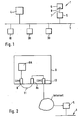
- FIG. 1 a field bus 1 with several connected field devices 10, 20, 30 is shown.
- the field devices 10, 20, 30 are connected via a data bus 3 to a control system 4 or via a fieldbus adapter 5 (eg CommuBox from Endress + Hauser) to a computing unit 9.
- a fieldbus adapter 5 eg CommuBox from Endress + Hauser
- the serial data transmission on the connecting line 7 is z. B. according to the RS232 or RS485 standard.
- the computer unit 9 is a personal computer (PC) or a portable laptop.
- Fieldbus 1 operates according to well-known international standards such as HART®, Profibus® or Foundation Fieldbus®.
- Examples of field devices include temperature measuring devices that detect the temperature of a process medium, flow meter, the flow in a Detecting pipe sections or level gauges that determine the fill level of a product in a container. The corresponding measured values are transmitted to the control system 4 via the data bus line 3. Based on the measured values determined, the control system 4 controls the entire process sequence.
- intelligent field devices also allow the transmission of various information stored in the field device.
- various parameters can be called up or changed by the control system 4 or by the computer unit 9.
- parameters are, for example, the zero point, the measuring range (span) or the unit in which the measured value is output.
- echo curves can be read out, for example, in the case of fill level measuring devices which work according to the echo principle. From the echo curve conclusions can be made on the functionality of the level.
- diagnostic information can also be called up.
- Fig. 2 shows a computer unit 9 according to a first embodiment of the invention.
- the computer unit 9 has, in addition to a first COM interface 8, a second COM interface 8a.
- the two interfaces 8 and 8a are connected to each other via a null modem cable 11.
- the computer unit 9 has a network interface, for example an Internet interface 13, which is connected via the Internet to a fieldbus adapter 5 connected to the fieldbus 1.
- the operating and monitoring program BA accesses the COM1 interface 8 of the computer unit 9 in the usual way. Via the null modem cable 11 and the COM2 interface 8a, the data connection with the Internet interface 13 takes place.
- the Internet interface 13 provides with the corresponding driver program (bus client) for the implementation of the data on TCP / IP standard, as well as a stored address book, the Selection of the corresponding Internet address of the fieldbus adapter 5.
- the data is exchanged between computer unit 9 and fieldbus adapter 5 via the Internet.
- the fieldbus adapter ensures that the protocol is converted to the appropriate fieldbus standard, eg HART®.
- a further advantage is that without a mechanical change over, via the Internet interface 13 of several different field buses can be controlled.
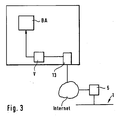
- Fig. 3 shows an alternative embodiment of the invention.
- the connection between the operating and monitoring program BA and the Internet interface 13 via a virtual interface V is also suitable for computer units 9, which have no two COM interfaces, which is often the case with laptops.
- the essential idea of the invention is that access to field devices via the Internet is possible with conventional operator control and monitoring programs without the need for elaborate rewriting of the source code of the operator control and monitoring program. This is especially important if the source code of the operator control and monitoring program is not known because it is not a proprietary program.
- the invention is not limited to the Internet as a network, but also in WANs (Wide Area Networks) or LANs (Local Area Networks) can be used.
- WANs Wide Area Networks
- LANs Local Area Networks
Landscapes
- Engineering & Computer Science (AREA)
- General Engineering & Computer Science (AREA)
- Manufacturing & Machinery (AREA)
- Quality & Reliability (AREA)
- Physics & Mathematics (AREA)
- General Physics & Mathematics (AREA)
- Automation & Control Theory (AREA)
- Testing And Monitoring For Control Systems (AREA)
- Debugging And Monitoring (AREA)
- Computer And Data Communications (AREA)
- Mobile Radio Communication Systems (AREA)
Abstract
Description
Die Erfindung bezieht sich auf den Datenaustausch zwischen einem Bedien- und Beobachtungsprogramm und einem Feldgerät.The invention relates to the data exchange between an operator control and monitoring program and a field device.
In der Prozeßleittechnik werden vielfach Feldgeräte zur Erfassung und Beeinflussung von Prozeßgrößen eingesetzt.
Beispiele für Feldgeräte sind Temperatur-Meßgeräte, die die Temperatur eines Prozeßmediums erfassen, Durchflußmesser, die den Durchfluß eines Prozeßmediums in einem Rohrleitungsabschnitt erfassen oder Füllstandsmesser, die den Füllstand einer Flüssigkeit oder eines Schüttgutes in einem Behälter bestimmen.In the field of process control field devices are often used to detect and influence process variables.
Examples of field devices are temperature gauges that detect the temperature of a process medium, flow meters that detect the flow of a process fluid in a pipe section or level gauges that determine the level of a liquid or a bulk material in a container.
Die Prozeßsteuerung erfolgt von einem Leitsystem aus, das mit den einzelnen Feldgeräten über einen Datenbus verbunden ist. Über den Datenbus werden alle für die Prozeßsteuerung notwendigen Informationen zwischen dem Leitsystem und den Feldgeräten ausgetauscht.
Ein vielfach eingesetzter Datenbus arbeitet nach dem HART-Standard, der HART® Foundation. Feldgeräte die nach dem HART-Standard arbeiten, werden auch als HART-Geräte bezeichnet.
Daneben werden in der Prozeßautomatisierungstechnik als Feldbusse u.a. noch Profibus® oder Foundation Fieldbus® eingesetzt.The process control is carried out by a control system which is connected to the individual field devices via a data bus. All data necessary for process control is exchanged between the control system and the field devices via the data bus.
A frequently used data bus works according to the HART standard, the HART® Foundation. Field devices that work according to the HART standard are also referred to as HART devices.
In addition, Profibus® or Foundation Fieldbus® are used as fieldbuses in process automation technology.
Neben der reinen Meßwertübertragung erlauben Feldgeräte auch die Übertragung von verschiedenen im Feldgerät abgespeicherten Informationen wie z. B. Parameter (Nullpunkt, Meßwertspanne etc.), Meßkurven sowie Diagnoseinformationen. Die Parameter können vom Leitsystem oder von einem Bedien- und Anzeigegerät aus eingestellt werden.
Dieser Vorgang wird auch als Konfigurierung und Parametrierung des Feldgerätes bezeichnet.In addition to the pure measured value transmission field devices also allow the transmission of various information stored in the field device such. B. parameters (zero point, span, etc.), curves and diagnostic information. The parameters can be set by the control system or by a control and display unit.
This process is also referred to as configuration and parameterization of the field device.
Bei jeder Erstinstallation oder bei einem Gerätetausch muß das Feldgerät konfiguriert und parametriert werden.For each initial installation or device replacement, the field device must be configured and parameterized.
Die Bedien- und Beobachtungsprogramme laufen meist auf Rechnereinheiten (PCs, Laptops), die über eine serielle COM-Schnittstelle (z.B. RS232, RS485) mit einem an den Feldbus angeschlossenes Feldbusadapter verbunden sind.The operator control and monitoring programs usually run on computer units (PCs, laptops), which are connected via a serial COM interface (for example, RS232, RS485) to a fieldbus adapter connected to the fieldbus.
Auf dem Markt erhältliche Bedien- und Beobachtungsprogramme sind z.B. CommuWin von der Firma Endress+Hauser Maulburg oder ReadWin von der Firma Endress+Hauser Wetzer.Operator control and monitoring programs available on the market are e.g. CommuWin from the company Endress + Hauser Maulburg or ReadWin from the company Endress + Hauser Wetzer.
Nachteilig an diesen Standard-Anwendungsprogramme ist, daß sie nur in unmittelbarer Nähe zum Feldbus eingesetzt werden können, da eine Kabelverbindung zwischen Rechnereinheit und Feldbusadapter notwendig ist. Ein Datenaustausch über größere Entfernungen (im Extremfall weltweit) ist somit nicht möglich.
Prinzipiell können Standard-Anwendungsprogramme so umgeschrieben werden, daß sie über eine Internetschnittstelle auf die Feldgeräte zugreifen. Dies bedeutet jedoch einen erheblichen Programmieraufwand und umfangreiche Anpassungen.A disadvantage of these standard application programs is that they can only be used in close proximity to the fieldbus, since a cable connection between the computer unit and fieldbus adapter is necessary. Data exchange over longer distances (in extreme cases worldwide) is therefore not possible.
In principle, standard application programs can be rewritten in such a way that they access the field devices via an Internet interface. However, this means a considerable amount of programming and extensive adjustments.
Weiterhin sind Anwendungsprogramme für Leitsysteme bekannt, die über eine Internetschnittstelle aufs Internet zugreifen und über entsprechende Gateways die Verbindung zu Feldbussen schaffen. Dadurch wird ein Zugriff auf Feldgeräte weltweit möglich.
Anwendungsprogramme für Leitsysteme sind meist sehr umfangreich und teuer.Furthermore, application programs for control systems are known which access the Internet via an Internet interface and establish the connection to field buses via corresponding gateways. This allows access to field devices worldwide.
Application programs for control systems are usually very extensive and expensive.
Aus der Druckschrift
Aus der Druckschrift
Der Erfindung liegt die Aufgabe zugrunde, Verfahren zum Datenaustausch zwischen einem Bedien- und Beobachtungsprogramm und einem Feldgerät zu schaffen, das mit einfachen Mitteln, unter Verwendung von Standard-Anwendungsprogrammen, den Zugriff auf Feldgeräte über größere Entfernungen via Internet ermöglichen.The invention has for its object to provide a method for data exchange between an operator control and observation program and a field device, which allow simple means, using standard application programs, access to field devices over greater distances via the Internet.
Gelöst wird diese Aufgabe durch die alternativen Verfahren zum Datenaustausch zwischen einem Bedien- und Beobachtungsprogramm und einem Feldgerät. wie sie in den Anpruchen 1 und 2 beschrieben sind, sowie durch das alternative Rechnersystem gemäß Anspruch 6 und die Rechnereinheit gemäß Anspruch 7.This problem is solved by the alternative methods for data exchange between an operator control and monitoring program and a field device. as described in claims 1 and 2, as well as by the alternative computer system according to claim 6 and the computer unit according to claim 7.
Die wesentliche Idee der Erfindung besteht darin, daß das Bedien- und Beobachtungsprogramm weiterhin auf eine serielle Schnittstelle zugreift. Das Bedien- und Beobachtungsprogramm "sieht" deshalb nicht, daß die Verbindung zum Feldgerät nicht über eine RS232-Verbindung sondern über das Internet erfolgt.The essential idea of the invention is that the operating and monitoring program continues to access a serial interface. The operating and monitoring program therefore does not "see" that the connection to the field device is not made via an RS232 connection but via the Internet.
Vorteilhafte Weiterentwicklungen der Erfindung sind in den Unteransprüchen angegeben.Advantageous developments of the invention are specified in the subclaims.
Gemäß ersten Ausgestaltung der Erfindung erfolgt die Verbindung zwischen dem Bedien- und Beobachtungsprogramm und der Internetschnittstelle über eine erste COM-Schnittstelle, ein Nullmodem-Kabel und eine zweite COM-Schnittstelle.
Hierbei erfolgt die Verbindung über zwei physikalisch vorhandene Schnittstellen z.B. COM1 und COM2 der Rechnereinheit, auf de das Bedien- und Beobachtungsprogramm läuft.
Diese Anwendung benötigt nur einen entsprechenden Treiber für die Intemetschnittstelle, der die Protokollumwandlung vornimmt und die Adressen für die Feldbusadapter verwaltet.According to the first embodiment of the invention, the connection between the operating and monitoring program and the Internet interface via a first COM interface, a null modem cable and a second COM interface.
In this case, the connection is made via two physical interfaces, eg COM1 and COM2 of the computer unit, on which the operating and monitoring program is running.
This application only needs a corresponding driver for the Internet interface, which does the protocol conversion and manages the addresses for the fieldbus adapters.
Gemäß der zweiten Ausgestaltung der Erfindung erfolgt die Verbindung zwischen Bedien- und Beobachtungsprogramm und Internetschnittstelle über eine virtuelle serielle Schnittstellen.
Diese Ausgestaltung erfordert zwar einen etwas höheren Programmieraufwand, sie ist aber auch bei Rechnereinheiten insbesondere Laptops einsetzbar, die keine zwei physikalisch vorhandene seriellen Schnittstellen aufweist.According to the second embodiment of the invention, the connection between the operating and monitoring program and the Internet interface via a virtual serial interfaces.
Although this embodiment requires a somewhat higher programming effort, it can also be used with computer units, in particular laptops, which does not have two physically present serial interfaces.
Die Erfindung wird anhand der nachfolgenden Zeichnungen näher erläutert. Es zeigt:
-
Fig. 1 : Feldbus mit Rechnereinheit und mehreren Feldgeräten in schematischer Darstellung, -
Fig. 2 : Rechnereinheit gemäß einer ersten Ausgestaltung der Erfindung, -
Fig. 3 : Rechnereinheit gemäß einer zweiten Ausgestaltung der Erfindung.
-
Fig. 1 : Fieldbus with computer unit and several field devices in a schematic representation, -
Fig. 2 In: Computer unit according to a first embodiment of the invention, -
Fig. 3 : Computer unit according to a second embodiment of the invention.
In
Die Feldgeräte 10, 20, 30 sind über eine Datenbusleitung 3 mit einem Leitsystem 4 bzw. über einen Feldbusadapter 5 ( z.B. CommuBox der Firma Endress + Hauser ) mit einer Recheneinheit 9 verbunden. Hierzu führt vom Feldbusadapter 5 eine Verbindungsleitung 7 zum COM-Steckeranschluss 8 der Rechnereinheit 9. Die serielle Datenübertragung auf der Verbindungsleitung 7 erfolgt z. B. nach dem RS232 oder RS485 Standard.
Bei der Rechnereinheit 9 handelt es sich um Personal Computer (PC) oder um einen tragbaren Laptop.
Der Fieldbus 1 arbeitet nach den bekannten internationalen Standards wie z.B. HART®, Profibus® oder Foundation Fieldbus®.In
The
The
Fieldbus 1 operates according to well-known international standards such as HART®, Profibus® or Foundation Fieldbus®.
Beispiele für Feldgeräte sind z.B. Temperatur-Meßgeräte, die die Temperatur eines Prozeßmediums erfassen, Durchflußmesser, die den Durchfluß in einem Rohrleitungsabschnitt erfassen oder Füllstandsmesser, die den Füllstand eines Füllgutes in einem Behälter bestimmen.
Die entsprechenden Meßwerte werden über die Datenbusleitung 3 an das Leitsystem 4 übertragen. Aufgrund der ermittelten Meßwerte steuert das Leitsystem 4 den gesamten Prozeßablauf.Examples of field devices include temperature measuring devices that detect the temperature of a process medium, flow meter, the flow in a Detecting pipe sections or level gauges that determine the fill level of a product in a container.
The corresponding measured values are transmitted to the control system 4 via the
Neben der reinen Meßwertübertragung erlauben intelligente Feldgeräte (smart field devices) auch die Übertragung von verschiedenen im Feldgerät abgespeicherten Informationen. So lassen sich verschiedenen Parameter vom Leitsystem 4 bzw. von der Rechnereinheit 9 aus aufrufen bzw. verändern. Derartige Parameter sind z.B. der Nullpunkt, der Meßbereich (Spanne) oder die Einheit in der der Meßwert ausgegeben wird.
Weiterhin können etwa bei Füllstandsmeßgeräten, die nach dem Echo-Prinzip arbeiten, Echo-Kurven ausgelesen werden. Aus der Echo-Kurve können Rückschlüsse auf die Funktionsfähigkeit des Füllstandsmeßgerätes getroffen werden.
Daneben können auch Diagnoseinformationen abgerufen werden. Einigen Feldgeräte sind bereits in der Lage eine Eigendiagnose durchzuführen. D. h. es werden bestimmte Kenngrößen des Feldgerätes auf Abweichungen vom Sollwert überwacht.In addition to pure measured value transmission, intelligent field devices (smart field devices) also allow the transmission of various information stored in the field device. Thus, various parameters can be called up or changed by the control system 4 or by the
Furthermore, echo curves can be read out, for example, in the case of fill level measuring devices which work according to the echo principle. From the echo curve conclusions can be made on the functionality of the level.
In addition, diagnostic information can also be called up. Some field devices are already able to carry out a self-diagnosis. Ie. certain characteristics of the field device are monitored for deviations from the setpoint.
Zur Darstellung dieser Informationen und Änderung der Parameter dienen spezielle Bedien- und Beobachtungsprogramme.
Diese Bedien- und Beobachtungsprogramme werden auf der Rechnereinheit 9 installiert. Herkömmliche Programme greifen direkt auf die COM-Schnittstelle 8 der Rechnereinheit 9 zu.To display this information and to change the parameters, special operating and monitoring programs are used.
These operating and monitoring programs are installed on the
Die beiden Schnittstellen 8 und 8a sind über ein Nullmodem-Kabel 11 miteinander verbunden.
The two
Die Rechnereinheit 9 weist eine Netzwerkschnittstelle z.B. eine Internetschnittstelle 13, die über das Internet mit einem an den Feldbus 1 angeschlossenen Feldbusadapter 5 verbunden ist.
Das Bedien- und Beobachtungprogramm BA greift in gewohnter Weise auf die COM1 Schnittstelle 8 der Rechnereinheit 9 zu. Über das Nullmodem-Kabel 11 und die COM2 Schnittstelle 8a erfolgt die Datenverbindung mit der Internetschnittstelle 13. Die Internetschnittstelle 13 sorgt mit dem entsprechenden Treiberprogramm (Bus-Client) für die Umsetzung der Daten auf TCP/IP Standard, sowie über ein gespeichertes Adreßbuch, die Auswahl der entsprechenden Internetadresse des Feldbusadapters 5. Über das Internet werden die Daten zwischen Rechnereinheit 9 und Feldbusadapter 5 ausgetauscht. Der Feldbusadapter sorgt für die Umwandlung des Protokolls auf den entsprechenden Feldbusstandard z.B. HART®. Als weiterer Vorteil ist zu nennen, daß ohne ein mechanisches Umstecken, über die Internetschnittstelle 13 mehrerer verschiedenen Feldbusse angesteuert werden können.The
The operating and monitoring program BA accesses the
Hierbei erfolgt die Verbindung zwischen dem Bedien- und Beobachtungsprogramm BA und der Internetschnittstelle 13 über eine virtuelle Schnittstelle V.
Diese Ausgestaltung der Erfindung erfordert zwar einen höheren Programmieraufwand, da ein Software-Programm für die virtuelle Schnittstelle geschrieben werden muß. Der Vorteil hier ist aber, daß sie auch für Rechnereinheiten 9 geeignet ist, die keine zwei COM-Schnittstellen aufweisen, was vielfach bei Laptops der Fall ist.
Here, the connection between the operating and monitoring program BA and the
Although this embodiment of the invention requires a higher programming effort, since a software program for the virtual interface must be written. The advantage here is that it is also suitable for
Die wesentliche Idee der Erfindung besteht darin, daß mit herkömmlichen Bedien-und Beobachtungsprogramme ein Zugriff auf Feldgeräte via Internet möglich ist, ohne daß eine aufwendige Umschreibung des Quell-Codes des Bedien- und Beobachtungsprogramms notwendig ist. Dies ist vor allem dann wichtig, wenn der Quell-Code des Bedien- und Beobachtungsprogramms nicht bekannt ist, weil es sich nicht um ein firmeneigenes Programm handelt.The essential idea of the invention is that access to field devices via the Internet is possible with conventional operator control and monitoring programs without the need for elaborate rewriting of the source code of the operator control and monitoring program. This is especially important if the source code of the operator control and monitoring program is not known because it is not a proprietary program.
Die Erfindung ist nicht auf das Internet als Netzwerk beschränkt, sondern auch bei WANs (Wide Area Networks) oder LANs (Local Area Networks) einsetzbar.The invention is not limited to the Internet as a network, but also in WANs (Wide Area Networks) or LANs (Local Area Networks) can be used.
Claims (7)
- Process for exchanging data between an operating and observation program (BA) and a field device (10, 20, 30) that is connected to a network - e.g. WAN, LAN or Internet - by means of a fieldbus adapter (5),
where the operating and observation program (BA) runs on a computer unit (9), which is connected to the network - e.g. WAN, LAN or Internet - by means of a network interface (13) and which exhibits a serial port (8),
characterized in that the operating and observation program (BA) is connected to the network interface (13) and accesses the network interface (13) by means of the serial port (8) for the purpose of exchanging data with the field device (10, 20, 30), where the connection between the operating and observation program (BA) and the network interface (13) takes place by means of the serial port (8) designed as the first COM port, a null modem cable (11) and a second COM port (8a) of the computer unit (9). - Process for exchanging data between an operating and observation program (BA) and a field device (10, 20, 30) that is connected to a network - e.g. WAN, LAN or Internet - by means of a fieldbus adapter (5),
where the operating and observation program (BA) runs on a computer unit (9) which is connected to the network by means of a network interface (13), characterized in that the operating and observation program (BA) is connected to the network interface by means of a virtual interface (V) and accesses the network interface (13) via the virtual interface (V) for the purpose of exchanging data with the field device (10, 20, 30). - Process as per one of the previous Claims 1 to 2 characterized in that the fieldbus adapter (5) works using the HART® standard.
- Process as per one of the previous Claims 1 to 3 characterized in that the fieldbus adapter (5) works using the Profibus® standard.
- Process as per one of the previous Claims 1 to 3 characterized in that the fieldbus adapter (5) works using the Foundation Fieldbus® standard.
- Computer system for exchanging data between an operating and observation program (BA) and a field device (10, 20, 30) which is connected to a network - e.g. WAN, LAN or Internet - by means of a fieldbus adapter (5), with the system comprising a computer unit (9) and a null modem cable (11) where the computer unit (9) exhibits a serial port (8) designed as the first COM port, a network interface (13) for connecting the computer unit (9) to the network - e.g. WAN, LAN or Internet - as well as a second COM port (8a), and where the first COM port (8) and the second COM port (8a) are connected to one another by means of the null modem cable (11) and the computer unit (9) comprises resources for running the data exchange process as per one of the Claims 1 or 3-5.
- Computer unit (9) for exchanging data between an operating and observation program (BA) and a field device (10, 20, 30) that is connected to a network - e.g. WAN, LAN or Internet - by means of a fieldbus adapter (5), with the computer unit (9) comprising a virtual interface (V), a network interface (13) for connecting the computing unit (9) to the network - e.g. WAN, LAN or Internet - and resources for running the data exchange process as per one of the Claims 2-5.
Applications Claiming Priority (3)
| Application Number | Priority Date | Filing Date | Title |
|---|---|---|---|
| DE10136732 | 2001-07-25 | ||
| DE10136732A DE10136732A1 (en) | 2001-07-25 | 2001-07-25 | Method for data exchange between an operating and monitoring program and a field device |
| PCT/EP2002/007975 WO2003010613A1 (en) | 2001-07-25 | 2002-07-18 | Method for data exchange between an operating and monitoring program and a field device |
Publications (2)
| Publication Number | Publication Date |
|---|---|
| EP1410121A1 EP1410121A1 (en) | 2004-04-21 |
| EP1410121B1 true EP1410121B1 (en) | 2008-08-27 |
Family
ID=7693360
Family Applications (1)
| Application Number | Title | Priority Date | Filing Date |
|---|---|---|---|
| EP02754901A Expired - Lifetime EP1410121B1 (en) | 2001-07-25 | 2002-07-18 | Method for data exchange between an operating and monitoring program and a field device |
Country Status (7)
| Country | Link |
|---|---|
| EP (1) | EP1410121B1 (en) |
| JP (1) | JP2005516270A (en) |
| CN (1) | CN100514235C (en) |
| AT (1) | ATE406604T1 (en) |
| CA (1) | CA2454968C (en) |
| DE (2) | DE10136732A1 (en) |
| WO (1) | WO2003010613A1 (en) |
Families Citing this family (10)
| Publication number | Priority date | Publication date | Assignee | Title |
|---|---|---|---|---|
| JP2006033651A (en) * | 2004-07-21 | 2006-02-02 | Yokogawa Electric Corp | Communications system |
| DE102004037064A1 (en) * | 2004-07-30 | 2006-02-16 | Abb Patent Gmbh | Method and device for functional testing of a field device before its initial commissioning |
| US7675932B2 (en) * | 2006-11-09 | 2010-03-09 | Rosemount Inc. | Adapter for providing digital communication between a field device and a computer |
| JP2010244296A (en) * | 2009-04-06 | 2010-10-28 | Mitsubishi Electric Engineering Co Ltd | Monitor and control system |
| DE102009045384A1 (en) * | 2009-10-06 | 2011-04-07 | Endress + Hauser Process Solutions Ag | Method for operating a fieldbus interface |
| US8804717B2 (en) | 2011-05-27 | 2014-08-12 | Nomadix, Inc. | Serial redirector device and associated methods |
| DE102011082004A1 (en) * | 2011-09-01 | 2013-03-07 | Endress + Hauser Gmbh + Co. Kg | Audio converter for data exchange between e.g. mobile phone and valve or field bus of overfill safety system for measuring filling level in liquid tank, has modulator transmitting audio signals to jack bush of mobile device |
| DE102013213040B4 (en) * | 2013-07-03 | 2019-07-04 | Vega Grieshaber Kg | Transmission device for a measuring device and method for transmitting raw data with a transmission device |
| EP3336631B1 (en) * | 2016-12-16 | 2021-06-16 | Siemens Aktiengesellschaft | Process control system and system planning tool |
| KR102211876B1 (en) * | 2020-07-14 | 2021-02-03 | 강재종 | Internet of things interworking devices and method for traditional fieldbus-based automatic control systems |
Family Cites Families (5)
| Publication number | Priority date | Publication date | Assignee | Title |
|---|---|---|---|---|
| US5765021A (en) * | 1996-03-27 | 1998-06-09 | Pc-Tel, Inc. | Computer system having second program for transferring data between second port connected to a first port and the software portion of a modem |
| DE19739297C2 (en) * | 1997-09-08 | 2001-11-15 | Phoenix Contact Gmbh & Co | Automation system and connection device for transparent communication between two networks |
| US6370448B1 (en) * | 1997-10-13 | 2002-04-09 | Rosemount Inc. | Communication technique for field devices in industrial processes |
| TW436709B (en) * | 1997-11-17 | 2001-05-28 | Ibm | Method and apparatus for interacting with hardware devices remotely |
| FI111760B (en) * | 1999-04-16 | 2003-09-15 | Metso Automation Oy | Wireless control of a field device in an industrial process |
-
2001
- 2001-07-25 DE DE10136732A patent/DE10136732A1/en not_active Withdrawn
-
2002
- 2002-07-18 JP JP2003515925A patent/JP2005516270A/en active Pending
- 2002-07-18 EP EP02754901A patent/EP1410121B1/en not_active Expired - Lifetime
- 2002-07-18 CN CNB028143744A patent/CN100514235C/en not_active Expired - Fee Related
- 2002-07-18 AT AT02754901T patent/ATE406604T1/en not_active IP Right Cessation
- 2002-07-18 WO PCT/EP2002/007975 patent/WO2003010613A1/en not_active Ceased
- 2002-07-18 DE DE50212710T patent/DE50212710D1/en not_active Expired - Lifetime
- 2002-07-18 CA CA002454968A patent/CA2454968C/en not_active Expired - Fee Related
Also Published As
| Publication number | Publication date |
|---|---|
| JP2005516270A (en) | 2005-06-02 |
| DE50212710D1 (en) | 2008-10-09 |
| WO2003010613A1 (en) | 2003-02-06 |
| CN100514235C (en) | 2009-07-15 |
| ATE406604T1 (en) | 2008-09-15 |
| DE10136732A1 (en) | 2003-02-13 |
| EP1410121A1 (en) | 2004-04-21 |
| CN1533522A (en) | 2004-09-29 |
| CA2454968A1 (en) | 2003-02-06 |
| CA2454968C (en) | 2009-05-19 |
Similar Documents
| Publication | Publication Date | Title |
|---|---|---|
| EP1558975B1 (en) | Method for the offline parameterisation of a field appliance used in process automation technology | |
| EP1525518B9 (en) | Method for updating device descriptions for field devices in process automation technology | |
| DE102009028051B4 (en) | System for operating a field device via a remote terminal | |
| DE10144971A1 (en) | Method for securing data exchange between an external access unit and a field bus device that is used in monitoring a physical or chemical process variable, particularly for securing data exchange between a WAN and a LAN field bus | |
| EP2188600A2 (en) | Method for monitoring a process system having a field bus in the process automation technology | |
| DE102009046806A1 (en) | Method for providing device-specific information of a field device of automation technology | |
| DE102007054417A1 (en) | Determining device-internal parameter addresses from fieldbus-specific parameter addresses of a field device | |
| EP1410121B1 (en) | Method for data exchange between an operating and monitoring program and a field device | |
| WO2013083410A2 (en) | Device for operating at least one automation technology field device | |
| DE102012105446B4 (en) | Device for determining and / or monitoring a chemical or physical process variable in automation technology | |
| DE102007058606A1 (en) | Method for integrating device objects into an object-based management system for field devices in automation technology | |
| DE102007059671A1 (en) | A method of operating a system comprising a field device and an operating system | |
| DE102010063854A1 (en) | Method for providing device-specific information of a field device of automation technology and / or for operating a field device | |
| CH702454B1 (en) | Arrangement with a superordinate control unit and at least one connected with the control unit intelligent field device. | |
| DE102011005062A1 (en) | Method for providing data from field device in automation system, arranged on network, involves instantiating an additional application-specific data, in automation/integration platform and making the data available to remote client | |
| EP1468356A2 (en) | Automated method for generating program modules used for controlling field devices by means of a machine-readable parametered description of the field devices | |
| DE10250250B4 (en) | Method for parameterizing a field device of process automation technology | |
| WO2011006740A1 (en) | System for controlling and/or monitoring a process system in automation engineering | |
| DE69707425T2 (en) | METHOD AND DEVICE WITH DEVICE DESCRIPTION FOR CONVENTIONAL DEVICE | |
| WO2012028367A1 (en) | System for multiple clients to communicate with multiple field devices in automation technology | |
| DE10157764A1 (en) | Method for data exchange between a field device and a radio telephone | |
| WO2010015455A1 (en) | Method for the safe operation of a field device | |
| DE102013114406A1 (en) | Method for parameterizing a field device of automation technology | |
| EP1478990A2 (en) | Method for transferring field device data to an external data bank | |
| DE102004009563A1 (en) | Portable data transfer device for transferring data between a computer unit and a field unit in a field bus or automation system has data interfaces with which it can be connected to standard computer and field unit interfaces |
Legal Events
| Date | Code | Title | Description |
|---|---|---|---|
| PUAI | Public reference made under article 153(3) epc to a published international application that has entered the european phase |
Free format text: ORIGINAL CODE: 0009012 |
|
| 17P | Request for examination filed |
Effective date: 20031224 |
|
| AK | Designated contracting states |
Kind code of ref document: A1 Designated state(s): AT BE BG CH CY CZ DE DK EE ES FI FR GB GR IE IT LI LU MC NL PT SE SK TR |
|
| AX | Request for extension of the european patent |
Extension state: AL LT LV MK RO SI |
|
| RIN1 | Information on inventor provided before grant (corrected) |
Inventor name: GRIECH, REINHARD |
|
| RAP1 | Party data changed (applicant data changed or rights of an application transferred) |
Owner name: ENDRESS + HAUSER PROCESS SOLUTIONS AG |
|
| 17Q | First examination report despatched |
Effective date: 20061106 |
|
| RAP1 | Party data changed (applicant data changed or rights of an application transferred) |
Owner name: ENDRESS + HAUSER PROCESS SOLUTIONS AG |
|
| GRAP | Despatch of communication of intention to grant a patent |
Free format text: ORIGINAL CODE: EPIDOSNIGR1 |
|
| GRAS | Grant fee paid |
Free format text: ORIGINAL CODE: EPIDOSNIGR3 |
|
| GRAA | (expected) grant |
Free format text: ORIGINAL CODE: 0009210 |
|
| AK | Designated contracting states |
Kind code of ref document: B1 Designated state(s): AT BE BG CH CY CZ DE DK EE ES FI FR GB GR IE IT LI LU MC NL PT SE SK TR |
|
| REG | Reference to a national code |
Ref country code: GB Ref legal event code: FG4D Free format text: NOT ENGLISH |
|
| REG | Reference to a national code |
Ref country code: CH Ref legal event code: EP |
|
| REG | Reference to a national code |
Ref country code: IE Ref legal event code: FG4D Free format text: LANGUAGE OF EP DOCUMENT: GERMAN |
|
| REF | Corresponds to: |
Ref document number: 50212710 Country of ref document: DE Date of ref document: 20081009 Kind code of ref document: P |
|
| PG25 | Lapsed in a contracting state [announced via postgrant information from national office to epo] |
Ref country code: ES Free format text: LAPSE BECAUSE OF FAILURE TO SUBMIT A TRANSLATION OF THE DESCRIPTION OR TO PAY THE FEE WITHIN THE PRESCRIBED TIME-LIMIT Effective date: 20081208 Ref country code: NL Free format text: LAPSE BECAUSE OF FAILURE TO SUBMIT A TRANSLATION OF THE DESCRIPTION OR TO PAY THE FEE WITHIN THE PRESCRIBED TIME-LIMIT Effective date: 20080827 |
|
| PG25 | Lapsed in a contracting state [announced via postgrant information from national office to epo] |
Ref country code: FI Free format text: LAPSE BECAUSE OF FAILURE TO SUBMIT A TRANSLATION OF THE DESCRIPTION OR TO PAY THE FEE WITHIN THE PRESCRIBED TIME-LIMIT Effective date: 20080827 |
|
| REG | Reference to a national code |
Ref country code: IE Ref legal event code: FD4D |
|
| PG25 | Lapsed in a contracting state [announced via postgrant information from national office to epo] |
Ref country code: DK Free format text: LAPSE BECAUSE OF FAILURE TO SUBMIT A TRANSLATION OF THE DESCRIPTION OR TO PAY THE FEE WITHIN THE PRESCRIBED TIME-LIMIT Effective date: 20080827 Ref country code: IE Free format text: LAPSE BECAUSE OF FAILURE TO SUBMIT A TRANSLATION OF THE DESCRIPTION OR TO PAY THE FEE WITHIN THE PRESCRIBED TIME-LIMIT Effective date: 20080827 Ref country code: BG Free format text: LAPSE BECAUSE OF FAILURE TO SUBMIT A TRANSLATION OF THE DESCRIPTION OR TO PAY THE FEE WITHIN THE PRESCRIBED TIME-LIMIT Effective date: 20081127 |
|
| PG25 | Lapsed in a contracting state [announced via postgrant information from national office to epo] |
Ref country code: SK Free format text: LAPSE BECAUSE OF FAILURE TO SUBMIT A TRANSLATION OF THE DESCRIPTION OR TO PAY THE FEE WITHIN THE PRESCRIBED TIME-LIMIT Effective date: 20080827 Ref country code: PT Free format text: LAPSE BECAUSE OF FAILURE TO SUBMIT A TRANSLATION OF THE DESCRIPTION OR TO PAY THE FEE WITHIN THE PRESCRIBED TIME-LIMIT Effective date: 20090127 Ref country code: CZ Free format text: LAPSE BECAUSE OF FAILURE TO SUBMIT A TRANSLATION OF THE DESCRIPTION OR TO PAY THE FEE WITHIN THE PRESCRIBED TIME-LIMIT Effective date: 20080827 |
|
| PLBE | No opposition filed within time limit |
Free format text: ORIGINAL CODE: 0009261 |
|
| STAA | Information on the status of an ep patent application or granted ep patent |
Free format text: STATUS: NO OPPOSITION FILED WITHIN TIME LIMIT |
|
| PG25 | Lapsed in a contracting state [announced via postgrant information from national office to epo] |
Ref country code: EE Free format text: LAPSE BECAUSE OF FAILURE TO SUBMIT A TRANSLATION OF THE DESCRIPTION OR TO PAY THE FEE WITHIN THE PRESCRIBED TIME-LIMIT Effective date: 20080827 |
|
| 26N | No opposition filed |
Effective date: 20090528 |
|
| PG25 | Lapsed in a contracting state [announced via postgrant information from national office to epo] |
Ref country code: IT Free format text: LAPSE BECAUSE OF FAILURE TO SUBMIT A TRANSLATION OF THE DESCRIPTION OR TO PAY THE FEE WITHIN THE PRESCRIBED TIME-LIMIT Effective date: 20080827 |
|
| PG25 | Lapsed in a contracting state [announced via postgrant information from national office to epo] |
Ref country code: SE Free format text: LAPSE BECAUSE OF FAILURE TO SUBMIT A TRANSLATION OF THE DESCRIPTION OR TO PAY THE FEE WITHIN THE PRESCRIBED TIME-LIMIT Effective date: 20081127 |
|
| BERE | Be: lapsed |
Owner name: ENDRESS + HAUSER PROCESS SOLUTIONS A.G. Effective date: 20090731 |
|
| PG25 | Lapsed in a contracting state [announced via postgrant information from national office to epo] |
Ref country code: MC Free format text: LAPSE BECAUSE OF NON-PAYMENT OF DUE FEES Effective date: 20090731 |
|
| REG | Reference to a national code |
Ref country code: CH Ref legal event code: PL |
|
| PG25 | Lapsed in a contracting state [announced via postgrant information from national office to epo] |
Ref country code: CH Free format text: LAPSE BECAUSE OF NON-PAYMENT OF DUE FEES Effective date: 20090731 Ref country code: LI Free format text: LAPSE BECAUSE OF NON-PAYMENT OF DUE FEES Effective date: 20090731 |
|
| PG25 | Lapsed in a contracting state [announced via postgrant information from national office to epo] |
Ref country code: BE Free format text: LAPSE BECAUSE OF NON-PAYMENT OF DUE FEES Effective date: 20090731 |
|
| PG25 | Lapsed in a contracting state [announced via postgrant information from national office to epo] |
Ref country code: GR Free format text: LAPSE BECAUSE OF FAILURE TO SUBMIT A TRANSLATION OF THE DESCRIPTION OR TO PAY THE FEE WITHIN THE PRESCRIBED TIME-LIMIT Effective date: 20081128 |
|
| PG25 | Lapsed in a contracting state [announced via postgrant information from national office to epo] |
Ref country code: AT Free format text: LAPSE BECAUSE OF NON-PAYMENT OF DUE FEES Effective date: 20090718 |
|
| PG25 | Lapsed in a contracting state [announced via postgrant information from national office to epo] |
Ref country code: LU Free format text: LAPSE BECAUSE OF NON-PAYMENT OF DUE FEES Effective date: 20090718 |
|
| PG25 | Lapsed in a contracting state [announced via postgrant information from national office to epo] |
Ref country code: TR Free format text: LAPSE BECAUSE OF FAILURE TO SUBMIT A TRANSLATION OF THE DESCRIPTION OR TO PAY THE FEE WITHIN THE PRESCRIBED TIME-LIMIT Effective date: 20080827 |
|
| PG25 | Lapsed in a contracting state [announced via postgrant information from national office to epo] |
Ref country code: CY Free format text: LAPSE BECAUSE OF FAILURE TO SUBMIT A TRANSLATION OF THE DESCRIPTION OR TO PAY THE FEE WITHIN THE PRESCRIBED TIME-LIMIT Effective date: 20080827 |
|
| REG | Reference to a national code |
Ref country code: FR Ref legal event code: PLFP Year of fee payment: 15 |
|
| REG | Reference to a national code |
Ref country code: FR Ref legal event code: PLFP Year of fee payment: 16 |
|
| REG | Reference to a national code |
Ref country code: FR Ref legal event code: PLFP Year of fee payment: 17 |
|
| PGFP | Annual fee paid to national office [announced via postgrant information from national office to epo] |
Ref country code: DE Payment date: 20180723 Year of fee payment: 17 Ref country code: FR Payment date: 20180725 Year of fee payment: 17 |
|
| PGFP | Annual fee paid to national office [announced via postgrant information from national office to epo] |
Ref country code: GB Payment date: 20180719 Year of fee payment: 17 |
|
| REG | Reference to a national code |
Ref country code: DE Ref legal event code: R119 Ref document number: 50212710 Country of ref document: DE |
|
| GBPC | Gb: european patent ceased through non-payment of renewal fee |
Effective date: 20190718 |
|
| PG25 | Lapsed in a contracting state [announced via postgrant information from national office to epo] |
Ref country code: DE Free format text: LAPSE BECAUSE OF NON-PAYMENT OF DUE FEES Effective date: 20200201 Ref country code: GB Free format text: LAPSE BECAUSE OF NON-PAYMENT OF DUE FEES Effective date: 20190718 |
|
| PG25 | Lapsed in a contracting state [announced via postgrant information from national office to epo] |
Ref country code: FR Free format text: LAPSE BECAUSE OF NON-PAYMENT OF DUE FEES Effective date: 20190731 |