EP1410113B1 - Method and device for controlling a print process with high colour density - Google Patents
Method and device for controlling a print process with high colour density Download PDFInfo
- Publication number
- EP1410113B1 EP1410113B1 EP02758387A EP02758387A EP1410113B1 EP 1410113 B1 EP1410113 B1 EP 1410113B1 EP 02758387 A EP02758387 A EP 02758387A EP 02758387 A EP02758387 A EP 02758387A EP 1410113 B1 EP1410113 B1 EP 1410113B1
- Authority
- EP
- European Patent Office
- Prior art keywords
- toner
- marking
- latent
- colour density
- print image
- Prior art date
- Legal status (The legal status is an assumption and is not a legal conclusion. Google has not performed a legal analysis and makes no representation as to the accuracy of the status listed.)
- Expired - Lifetime
Links
Images

Classifications
-
- G—PHYSICS
- G03—PHOTOGRAPHY; CINEMATOGRAPHY; ANALOGOUS TECHNIQUES USING WAVES OTHER THAN OPTICAL WAVES; ELECTROGRAPHY; HOLOGRAPHY
- G03G—ELECTROGRAPHY; ELECTROPHOTOGRAPHY; MAGNETOGRAPHY
- G03G15/00—Apparatus for electrographic processes using a charge pattern
- G03G15/06—Apparatus for electrographic processes using a charge pattern for developing
- G03G15/08—Apparatus for electrographic processes using a charge pattern for developing using a solid developer, e.g. powder developer
- G03G15/0822—Arrangements for preparing, mixing, supplying or dispensing developer
- G03G15/0848—Arrangements for testing or measuring developer properties or quality, e.g. charge, size, flowability
- G03G15/0849—Detection or control means for the developer concentration
- G03G15/0855—Detection or control means for the developer concentration the concentration being measured by optical means
-
- G—PHYSICS
- G03—PHOTOGRAPHY; CINEMATOGRAPHY; ANALOGOUS TECHNIQUES USING WAVES OTHER THAN OPTICAL WAVES; ELECTROGRAPHY; HOLOGRAPHY
- G03G—ELECTROGRAPHY; ELECTROPHOTOGRAPHY; MAGNETOGRAPHY
- G03G15/00—Apparatus for electrographic processes using a charge pattern
- G03G15/50—Machine control of apparatus for electrographic processes using a charge pattern, e.g. regulating differents parts of the machine, multimode copiers, microprocessor control
- G03G15/5033—Machine control of apparatus for electrographic processes using a charge pattern, e.g. regulating differents parts of the machine, multimode copiers, microprocessor control by measuring the photoconductor characteristics, e.g. temperature, or the characteristics of an image on the photoconductor
- G03G15/5041—Detecting a toner image, e.g. density, toner coverage, using a test patch
-
- G—PHYSICS
- G03—PHOTOGRAPHY; CINEMATOGRAPHY; ANALOGOUS TECHNIQUES USING WAVES OTHER THAN OPTICAL WAVES; ELECTROGRAPHY; HOLOGRAPHY
- G03G—ELECTROGRAPHY; ELECTROPHOTOGRAPHY; MAGNETOGRAPHY
- G03G2215/00—Apparatus for electrophotographic processes
- G03G2215/00025—Machine control, e.g. regulating different parts of the machine
- G03G2215/00029—Image density detection
- G03G2215/00033—Image density detection on recording member
- G03G2215/00037—Toner image detection
- G03G2215/00042—Optical detection
Definitions
- the invention relates to a method for controlling the printing process in a printer or copier, wherein a character generator on a subcarrier generates a latent image and a latent toner mark. Furthermore, the invention relates to a device for carrying out the method.
- a latent printed image for example on a photoconductor, is first produced on an intermediate carrier, this latent printed image is inked and subsequently transferred to the carrier.
- the coloring of the printed image must be kept within narrow predetermined limits.
- Such a print image may include solid areas, halftone halftone areas, lines, characters, and other relatively complex picture elements.
- the degree of inking for the printed image is indirectly determined by means of a toner mark, and the printing process is controlled or regulated as a function of the printing result with this toner mark. Therefore, a latent toner mark is produced on the intermediate carrier in addition to the latent image which is important for the customer. Such a toner mark is relatively small compared to the area of the printed image.
- the DE-A-39 38 354 describes a method for controlling the printing process in an image forming device.
- the energy is lowered from the energy for creating a latent print image.
- a reflex sensor determines the color density of the inked toner brand. Depending on the signal of this reflex sensor, either the lamp voltage of the character generator, the bias for a developing process or the grid voltage of the main charger is set. The influence of the toner concentration in the development station is not described.
- the document DE-A-199 00 164 The same Applicant describes measuring the toner density of a toner mark. Depending on the measured value, the toner concentration is set.
- the document US-A-4,962,407 describes an electrophotographic copying device, wherein measuring signals of two reference marks of different color density are used to determine the toner concentration. From the difference signal for both toner brands is closed to the toner concentration and in case of deviation from a target value, the toner concentration is readjusted in the developer station.
- the documents DE-A-41 26 446 and DE-A-41 26 457 describe a developing unit for developing colored toner images, in which image patterns are scanned, which were generated by means of two different potentials. Based on the measured signals can then be closed to the toner concentration and tracked.
- the energy per unit area for producing the latent toner mark is lowered relative to the energy per unit area for producing the latent print image with an otherwise identical image structure.
- this energy is in the form of radiant energy.
- this radiant energy for generating the latent toner mark which is embodied, for example, as a solid surface, is lowered relative to the radiant energy of an equally large solid surface of the latent print image. This has the consequence that the color density of the solid surface of the toner mark is lower than the color density in the corresponding printed image.
- the signal of the reflection sensor which scans the toner mark is larger;
- the operating point of the reflection sensor is on a characteristic of the color density on the toner concentration in a steeper area. Accordingly, a change in the color density on the toner mark causes a correspondingly larger change in the signal of the reflection sensor, whereby the toner concentration can be tracked with a higher accuracy in order to achieve the desired color density on the printed printed image.
- a device having the features of claim 15 is provided.
- the technical effects achievable with this device have already been described in connection with the method.
- FIG. 1 schematically shows the structure of important components of a device for controlling an electrophotographic printing process.
- a character generator 10 is in the form of an LED comb. It contains a multiplicity of LEDs whose light is emitted onto the surface of a photoconductor drum 12 in order to generate there latent image structures in the form of a charge image.
- the character generator 10 emits light with the light output L1.
- This area a is an area in which print images are generated for the customer.
- the LEDs of the character generator 10 emit light for generating the structure of a toner mark 14.
- this light has a lower light output L2 than the light output L1 in the region a for a same image structure, in the present case a full-tone image structure.
- the toner-colored mark 14 (the process step of developing with toner was described in U.S.P. Fig. 1 omitted for clarity) is scanned on the photoconductor 12 by a reflection sensor 16.
- the toner-colored print image 18 is transferred to a paper web 20.
- the toner mark 14 is not included in the printed image 18 for the customer.
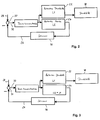
- Fig. 2 shows in a block diagram schematically the control of the coloring at high color density of the printed image for the customer.
- the blocks 22 and 24 describe the generation of the latent print image 18 and the latent toner mark 14, respectively.
- the light energy L2 of the LEDs for generating the latent toner mark is lowered by a constant factor compared to the light energy L1 for generating the latent print image 18. For example, this can be done by lowering the current that is supplied to the corresponding LEDs of the LED comb.
- the colored toner mark is scanned by means of the reflection sensor 16 and the measured color density is imaged in a signal 26. This signal 26 represents an actual value of the printing process. This actual value 26 is compared with a desired value 28.
- a setpoint-actual value comparator 30 determines the actual value deviation 32. Due to this deviation 32, the toner concentration is changed, for example, increased or decreased. For adjusting the toner concentration, it is possible, for example, to act on a conveyor coil which effects the toner transport to the developer station. With the thus-adjusted toner concentration, the print image 18 and the toner mark 14 are generated. The print image 18 is then output.
- Fig. 3 shows the example with normal and low color density; the same parts are the same.
- the lowering of the energy for generating the toner mark 14 is canceled, that is, the light power L2 is equal to the light power L1.
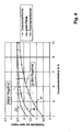
- Fig. 4 shows characteristics of the coloring as a function of the toner concentration in the developer station. Plotted is the color density on the printed paper on the toner concentration in percent. If the same light energy per unit area is used for the latent toner starch 14 and the latent print image 18 with respect to otherwise identical image structures, the characteristic 36 results. It should be noted that the toner mark has a relatively small area compared to the printed image 18. Accordingly, the coloring is darker and the color density is increased. The characteristic 38 results for a relatively large area of the printed image. The characteristic 40 shows the relationship of toner concentration and color density of the printed image on the paper when the latent mark is produced with a lowered light power L2.
- the characteristic curve 36 At the operating point with a toner concentration of 5% can be seen from the characteristic curve 36 that a relatively large color density is achieved on the paper.
- this characteristic curve 36 is very flat, so that with a change in the toner concentration, the color density on the paper barely changes, ie there is a very small control stroke for the control process.
- a large control stroke By lowering the light output, a large control stroke can be achieved with the same toner concentration, as the characteristic curve 40 shows.
- the slope of the characteristic or the value of the differential of the color density on the paper to the toner concentration is increased in the characteristic curve 40 at this operating point. That way, too Control accuracy improved to control the printing process.
- the reduction of the light output L2 for the production of the latent toner mark 14 can be greater, the greater the desired color density of the printed printed image on the paper.
- the reduction of the light power L2 for the toner mark 14 can also be such that the ratio or the differential quotient of toner concentration and color density at the operating point of the reflection sensor 16 exceeds a predetermined value.
- the characteristics 36, 38, 40 are not linear. In the range of low toner concentrations, a sufficient slope of the characteristic curve 36 is present. This means that a reduction in the light output L2 for the toner brand 14 is no longer absolutely necessary and can be reversed. Therefore, in one embodiment of the invention, starting from a color density value ⁇ a predetermined threshold value, the lowering of the light output is reversed.
- the intermediate carrier on which the toner mark 14 is applied may also be a photoconductor belt.
- the invention can also be used for electromagnetic. Printing method can be applied. It is also possible to transfer the toner mark 14 to a transfer belt and to scan this toner mark 14 on the transfer belt. Furthermore, it is possible to adjust the toner concentration on the basis of predetermined characteristics representing the relationship between color density on the substrate and the toner concentration with lowered energy for the generation of the latent mark.
Landscapes
- Physics & Mathematics (AREA)
- General Physics & Mathematics (AREA)
- Color Electrophotography (AREA)
- Control Or Security For Electrophotography (AREA)
- Dry Development In Electrophotography (AREA)
Description
Die Erfindung betrifft ein Verfahren zum Steuern des Druckprozesses bei einem Drucker oder Kopierer, bei dem ein Zeichengenerator auf einem Zwischenträger ein latentes Druckbild und eine latente Tonermarke erzeugt. Weiterhin betrifft die Erfindung eine Einrichtung zum Durchführen des Verfahrens.The invention relates to a method for controlling the printing process in a printer or copier, wherein a character generator on a subcarrier generates a latent image and a latent toner mark. Furthermore, the invention relates to a device for carrying out the method.
Bei elektrografisch arbeitenden Druckern oder Kopierern wird zur Erzeugung des gedruckten Bildes Tonermaterial entsprechend der Bildstruktur auf einen Trägerstoff, beispielsweise Papier, aufgebracht und fixiert. Beispiele für derartige Druckprozesse sind die elektrofotografischen Verfahren und das magnetoelektrische Verfahren. Hierbei wird zunächst auf einem Zwischenträger ein latentes Druckbild, zum Beispiel auf einem Fotoleiter, erzeugt, dieses latente Druckbild eingefärbt und nachfolgend auf den Träger übertragen. Zur Erzielung einer hohen Druckqualität muß die Einfärbung des Druckbildes innerhalb enger vorgegebener Grenzen gehalten werden. Ein derartiges Druckbild kann Vollflächen, gerasterte Halbtonflächen, Linien, Zeichen und andere, relativ komplexe Bildelemente enthalten. Zur genauen Steuerung des Druckprozesses wird anhand einer Tonermarke der Einfärbungsgrad für das Druckbild indirekt bestimmt und der Druckprozess abhängig vom Druckergebnis bei dieser Tonermarke gesteuert oder geregelt. Auf dem Zwischenträger wird daher neben dem für den Kunden wesentlichen latenten Druckbild auch eine latente Tonermarke erzeugt. Eine derartige Tonermarke ist verglichen mit der Fläche des Druckbildes relativ klein.In electrographically operating printers or copiers toner material according to the image structure on a support, such as paper, applied and fixed to generate the printed image. Examples of such printing processes are the electrophotographic processes and the magnetoelectric process. In this case, a latent printed image, for example on a photoconductor, is first produced on an intermediate carrier, this latent printed image is inked and subsequently transferred to the carrier. To achieve a high print quality, the coloring of the printed image must be kept within narrow predetermined limits. Such a print image may include solid areas, halftone halftone areas, lines, characters, and other relatively complex picture elements. For precise control of the printing process, the degree of inking for the printed image is indirectly determined by means of a toner mark, and the printing process is controlled or regulated as a function of the printing result with this toner mark. Therefore, a latent toner mark is produced on the intermediate carrier in addition to the latent image which is important for the customer. Such a toner mark is relatively small compared to the area of the printed image.
Bei hohen Farbdichten oder Einfärbungsgraden ist eine hohe Konzentration des Farbstoffes erforderlich, d.h. die zugehörige Tonermarke ist relativ dunkel. Beim Abtasten einer derartigen dunklen Tonermarke durch einen optischen Reflexionssensor ist dessen Empfindlichkeit verringert, d.h. die Kennlinie der Farbdichte auf der Tonermarke über die Tonerkonzentration verläuft relativ flach. Dies hat zur Folge, daß bei hohen Farbdichten die Einstellung der genauen Tonerkonzentration schwierig ist. Dieser Effekt wird noch dadurch vergrößert, daß kleine Flächen dunkler eingefärbt werden als große Flächen, d.h. die relativ kleinen Tonermarken sind dunkler eingefärbt als die größeren Flächenelemente des Druckbildes.At high ink densities or degrees of coloration, a high concentration of the dye is required, ie associated toner mark is relatively dark. When scanning such a dark toner mark by an optical reflection sensor whose sensitivity is reduced, ie the characteristic of the color density on the toner mark on the toner concentration is relatively flat. As a result, setting the exact toner concentration is difficult at high color densities. This effect is further enhanced by the fact that small areas are colored darker than large areas, ie the relatively small toner marks are colored darker than the larger area elements of the printed image.
Die
Das Dokument
Das Dokument
Das Dokument
Die Dokumente
Es ist die Aufgabe der Erfindung, ein Verfahren und eine Einrichtung zum Steuern des Druckprozesses anzugeben, bei dem auch bei hoher Farbdichte die Tonerkonzentration mit hoher Genauigkeit eingestellt werden kann.It is the object of the invention to provide a method and a device for controlling the printing process at which even at high color density, the toner concentration can be adjusted with high accuracy.
Diese Aufgabe wird für ein Verfahren durch die Merkmale des Anspruchs 1 gelöst.This object is achieved for a method by the features of
Gemäß der Erfindung wird die Energie je Flächeneinheit für das Erzeugen der latenten Tonermarke gegenüber der Energie je Flächeneinheit für das Erzeugen des latenten Druckbildes bei sonst gleicher Bildstruktur abgesenkt. Bei elektrofotografischen Druckprozessen z.B. liegt diese Energie in Form von Strahlungsenergie vor. Dies bedeutet, daß bei elektrofotografischen Prozessen diese Strahlungsenergie für das Erzeugen der latenten Tonermarke, die zum Beispiel als Volltonfläche ausgebildet ist, gegenüber der Strahlungsenergie einer gleich großen Volltonfläche des latenten Druckbildes abgesenkt wird. Dies hat zur Folge, daß die Farbdichte der Volltonfläche der Tonermarke geringer ist als die Farbdichte im entsprechenden Druckbild. Demgemäß ist das Signal des Reflexionssensors, der die Tonermarke abtastet, größer; außerdem liegt der Arbeitspunkt des Reflexionssensors auf einer Kennlinie der Farbdichte über die Tonerkonzentration in einem steileren Bereich. Eine Änderung der Farbdichte auf der Tonermarke bewirkt demgemäß eine entsprechend größere Änderung des Signals des Reflexionssensors, wodurch die Tonerkonzentration mit einer höheren Genauigkeit nachgeführt werden kann, um die gewünschte Farbdichte auf dem gedruckten Druckbild zu erzielen.According to the invention, the energy per unit area for producing the latent toner mark is lowered relative to the energy per unit area for producing the latent print image with an otherwise identical image structure. In electrophotographic printing processes e.g. this energy is in the form of radiant energy. This means that in electrophotographic processes, this radiant energy for generating the latent toner mark, which is embodied, for example, as a solid surface, is lowered relative to the radiant energy of an equally large solid surface of the latent print image. This has the consequence that the color density of the solid surface of the toner mark is lower than the color density in the corresponding printed image. Accordingly, the signal of the reflection sensor which scans the toner mark is larger; In addition, the operating point of the reflection sensor is on a characteristic of the color density on the toner concentration in a steeper area. Accordingly, a change in the color density on the toner mark causes a correspondingly larger change in the signal of the reflection sensor, whereby the toner concentration can be tracked with a higher accuracy in order to achieve the desired color density on the printed printed image.
Gemäß einem weiteren Aspekt der Erfindung wird eine Einrichtung mit den Merkmalen des Anspruchs 15 angegeben. Die mit dieser Einrichtung erzielbaren technischen Effekte sind im Zusammenhang mit dem Verfahren bereits beschrieben.According to a further aspect of the invention, a device having the features of claim 15 is provided. The technical effects achievable with this device have already been described in connection with the method.
Ein Ausführungsbeispiel der Erfindung wird im folgenden anhand der Zeichnung erläutert. Darin zeigt
- Fig. 1
- schematisch den Aufbau wichtiger Funktionselemente in einem elektrofotografischen Drucker,
- Fig. 2
- ein Blockschaltbild zur Regelung des Einfärbegrades bei einer Absenkung der Lichtleistung für die Tonermarke,
- Fig. 3
- die Einfärberegelung bei normaler und geringer Farbdichte, und
- Fig. 4
- ein Diagramm, welches die Einfärbung auf dem Papier als Druckbildträger abhängig von der Tonerkonzentration zeigt.
- Fig. 1
- schematically the construction of important functional elements in an electrophotographic printer,
- Fig. 2
- a block diagram for controlling the inking degree with a decrease in the light output for the toner brand,
- Fig. 3
- Dyeing at normal and low color density, and
- Fig. 4
- a diagram showing the coloring on the paper as a print image carrier depending on the toner concentration.
Dessen elektrisches Signal wird zum Steuern oder Regeln des Druckprozesses ausgenutzt, wie weiter unten noch genauer erläutert wird.Its electrical signal is used to control or regulate the printing process, as will be explained in more detail below.
In einem späteren Prozessschritt wird das mit Toner eingefärbte Druckbild 18 auf eine Papierbahn 20 übertragen. Die Tonermarke 14 ist im Druckbild 18 für den Kunden nicht enthalten.In a later process step, the toner-
Um das Druckbild für den Kunden mit der gewünschten Farbdichte oder dem gewünschten Einfärbungsgrad zu drucken werden eine Grundeinstellung und weitere Schritte vorgenommen:
- Schritt a:
- Es wird das vom Kunden gewünschte Druckbild mit einer am Drucker einstellbaren Farbdichte gedruckt.
- Schritt b:
- Mit Hilfe eines Densitometers wird die Farbdichte im Druckbild des Kunden gemessen. Diese Farbdichte ist ein logarithmisches Maß des Verhältnisses aus Reflexionsgrad des Hintergrunds zum Reflexionsgrad der Bildstruktur.
- Schritt c:
- Falls die gewünschte Farbdichte für das Druckbild des Kunden nicht erreicht wird, so wird die Tonerkonzentration manuell oder automatisch geändert, bis die tatsächliche Farbdichte mit der gewünschten Farbdichte übereinstimmt.
- Schritt d:
- Die Lichtleistung L2 für die Tonermarke ist bei hohen Farbdichten, d.h. bei dunklen Bildstrukturen im Druckbild gegenüber der Lichtleistung L1 abgesenkt.
- Schritt e:
- Die Grundeinstellung des Druckprozesses ist abgeschlossen. Beim anschließenden Drucken einer Vielzahl von Seiten wird die Tonerkonzentration so gesteuert oder geregelt, daß die mit der verringerten Lichtleistung L2 auf der Tonermarke vorhandene Farbdichte konstant bleibt.
- Step a:
- The print image desired by the customer is printed with a printer-adjustable color density.
- Step b:
- With the help of a densitometer, the color density in the printed image of the customer is measured. This color density is a logarithmic measure of the ratio of the reflectance of the background to the reflectance of the image structure.
- Step c:
- If the desired color density for the printed image of the customer is not reached, the toner concentration is changed manually or automatically until the actual color density matches the desired color density.
- Step d:
- The light output L2 for the toner mark is lowered at high color densities, ie at dark image structures in the printed image compared to the light output L1.
- Steps:
- The basic setting of the printing process is complete. In the subsequent printing of a plurality of pages, the toner concentration is controlled so that the color density existing on the toner mark with the reduced light power L2 remains constant.
Im Arbeitspunkt mit einer Tonerkonzentration von 5 % ist anhand der Kennlinie 36 zu erkennen, daß eine relativ große Farbdichte auf dem Papier erreicht wird. Diese Kennlinie 36 ist jedoch sehr flach, so daß bei einer Änderung der Tonerkonzentration sich die Farbdichte auf dem Papier kaum mehr ändert, d.h. es liegt ein sehr kleiner Regelhub für den Regelungsprozess vor. Durch Absenken der Lichtleistung kann ein großer Regelhub bei gleicher Tonerkonzentration erreicht werden, wie die Kennlinie 40 zeigt. Die Steigung der Kennlinie oder der Wert des Differentials der Farbdichte auf dem Papier zur Tonerkonzentration ist bei der Kennlinie 40 in diesem Arbeitspunkt vergrößert. Auf diese Weise wird auch die Regelgenauigkeit zum Regeln des Druckprozesses verbessert. Die Absenkung der Lichtleistung L2 für das Erzeugen der latenten Tonermarke 14 kann umso größer erfolgen, je größer die gewünschte Farbdichte des gedruckten Druckbildes auf dem Papier ist. Die Absenkung der Lichtleistung L2 für die Tonermarke 14 kann auch derart erfolgen, daß das Verhältnis oder der Differentialquotient aus Tonerkonzentration und Farbdichte im Arbeitspunkt des Reflexionssensors 16 einen vorgegebenen Wert überschreitet.At the operating point with a toner concentration of 5% can be seen from the
Wie anhand der
Es sind zahlreiche Varianten der beschriebenen Erfindung möglich. Beispielsweise kann der Zwischenträger, auf dem die Tonermarke 14 aufgebracht wird, auch ein Fotoleiterband sein. Die Erfindung kann auch für elektromagnetische. Druckverfahren angewendet werden. Auch ist es möglich, die Tonermarke 14 auf ein Transferband zu übertragen, und diese Tonermarke 14 auf dem Transferband abzutasten. Weiterhin ist es möglich, die Tonerkonzentration anhand vorgegebener Kennlinien einzustellen, die den Zusammenhang zwischen Farbdichte auf dem Trägermaterial und der Tonerkonzentration bei abgesenkter Energie für die Erzeugung der latenten Marke wiedergeben.Numerous variants of the described invention are possible. For example, the intermediate carrier on which the
- 1010
- Zeichengeneratorcharacter generator
- 1212
- FotoleitertrommerFotoleitertrommer
- 1414
- Tonermarketoner mark
- 1616
- Reflexionssensorreflective sensor
- 1818
- Druckbildprint image
- 2020
- Papierbahnpaper web
- 2222
- Funktionsblockfunction block
- 2424
- Funktionsblockfunction block
- 2626
- Signalsignal
- 2828
- Sollwertsetpoint
- 3030
- Sollwert-Istwert-VergleichSetpoint actual value comparison
- 3232
- Istwert-AbweichungActual value deviation
- 3636
- Kennliniecurve
- 3838
- Kennliniecurve
- 4040
- Kennliniecurve
- L1L1
- Lichtleistunglight output
- aa
- BereichArea
- bb
- BereichArea
- L2L2
- Lichtleistunglight output
Claims (27)
- Method to control the print process in a printer or copier,
in which a character generator (10) generates a latent print image (18) and a latent toner marking (14) on an intermediate carrier (12),
the exposure energy per area unit for the generation of the latent toner marking (14) is decreased in comparison to the energy per area unit for the generation of the latent print image (18), given an otherwise identical image structure,
the latent print image (18) and the latent toner marking (14) are inked with toner in a developer station,
an optical reflection sensor (16) determines the colour density of the inked toner marking (14), whereby via the stated decrease of the energy the slope of the characteristic line (40) of the colour density (40) of the toner marking (14) over the toner concentration increases,
and in that the toner concentration is adjusted in the developer station dependent on the signal of the reflection sensor (16). - Method according to claim 1, in that the toner concentration is adjusted in the developer station using a predetermined function of the colour density over the toner concentration.
- Method according to claim 1 or 2, in that the toner concentration is adjusted in a calibration event such that the desired colour density is present on the printed print image (18), and in that the signal of the optical reflection sensor (16) is determined for the toner marking (14).
- Method according to claim 3, in that the toner concentration is adjusted in a regulation process such that the signal determined by the reflection sensor (16) has a largely constant value for the toner marking (14).
- Method according to any of the preceding claims, in that the decrease of the energy for the generation of the latent marking (14) ensues ever greater the higher the desired colour density of the printed print image (18).
- Method according to any of the preceding claims, in that the decrease of the energy for the toner marking ensues such that the ratio or the differential quotient from toner concentration and colour density in the operating point of the reflection sensor (16) exceeds a predetermined value.
- Method according to any of the preceding claims, in that, for a colour density value greater than or equal to a predetermined threshold, the decrease of the energy for the toner marking is cancelled.
- Method according to any of the preceding claims, in that a densitometer is used to establish the colour density of the printed print image.
- Method according to any of the preceding claims, in that an electrophotographic print process is used as a print process for the printer or copier.
- Method according to claim 9, in that an LED character generator whose LEDs can be individually controlled is used as a character generator (10).
- Method according to any of the preceding claims, in that a photoconductor drum or a photoconductor band is used as an intermediate carrier (12).
- Method according to any of the preceding claims, in that the toner marking (14) is arranged outside of the region of the print image (18).
- Method according to claim 11 or 12, in that the toner marking (14) inked on the intermediate carrier (12) is scanned by the optical reflection sensor (16).
- Method according to any of the preceding claims, in that the toner marking is scanned on a transfer band.
- Device to control the print process in a printer or copier,
in which a character generator (10) generates a latent print image (18) and a latent toner marking (14) on an intermediate carrier (12),
means are provided that decrease the exposure energy per area unit for the generation of the latent toner marking (14) in comparison to the energy per area unit for the generation of the latent print image (18), given an otherwise identical image structure,
the latent print image (18) and the latent toner marking (14) are inked with toner in a developer station, an optical reflection sensor (16) determines the colour density of the inked toner marking (14), whereby via the stated decrease of the energy the slope of the characteristic line (40) of the colour density (40) of the toner marking (14) over the toner concentration increases,
and in that the toner concentration is adjusted in the developer station dependent on the signal of the reflection sensor (16). - Device according to claim 15, in that the toner concentration is adjusted in the developer station using a predetermined function of the colour density over the toner concentration.
- Device according to claim 15 or 16, in that the toner concentration is adjusted in a calibration event such that the desired colour density is present on the printed print image (18), and in that the signal of the optical reflection sensor (16) is determined for the toner marking (14).
- Device according to claim 17, in that the toner concentration is adjusted in a regulation process such that the signal determined by the reflection sensor (16) has a largely constant value for the toner marking (14).
- Device according to any of the preceding claims, in that the decrease of the energy for the generation of the latent marking (14) ensues ever greater the higher the desired colour density of the printed print image (18).
- Device according to any of the preceding claims, in that the decrease of the energy for the toner marking ensues such that the ratio or the differential quotient from toner concentration and colour density in the operating point of the reflection sensor (16) exceeds a predetermined value.
- Device according to any of the preceding claims, in that, for a colour density value greater than or equal to a predetermined threshold, the decrease of the energy for the toner marking is cancelled.
- Device according to any of the preceding claims, in that an electrophotographic print process is used as a print process for the printer or copier.
- Device according to claim 22, in that an LED character generator whose LEDs can be individually controlled is used as a character generator (10).
- Device according to any of the preceding claims, in that a photoconductor drum or a photoconductor band is used as an intermediate carrier (12).
- Device according to any of the preceding claims, in that the toner marking (14) is arranged outside of the region of the print image (18).
- Device according to claim 24 or 25, in that the toner marking (14) inked on the intermediate carrier (12) is scanned by the optical reflection sensor (16).
- Device according to any of the preceding claims, in that the toner marking is scanned on a transfer band.
Applications Claiming Priority (3)
| Application Number | Priority Date | Filing Date | Title |
|---|---|---|---|
| DE10136259 | 2001-07-25 | ||
| DE10136259A DE10136259A1 (en) | 2001-07-25 | 2001-07-25 | Method for controlling a printing process in a printer or copier uses a character generator to produce a toner mark on an intermediate carrier and a reflection sensor to determine color density for a colored toner mark |
| PCT/EP2002/008260 WO2003012553A1 (en) | 2001-07-25 | 2002-07-24 | Method and device for controlling a print process with high colour density |
Publications (2)
| Publication Number | Publication Date |
|---|---|
| EP1410113A1 EP1410113A1 (en) | 2004-04-21 |
| EP1410113B1 true EP1410113B1 (en) | 2008-07-09 |
Family
ID=7693065
Family Applications (1)
| Application Number | Title | Priority Date | Filing Date |
|---|---|---|---|
| EP02758387A Expired - Lifetime EP1410113B1 (en) | 2001-07-25 | 2002-07-24 | Method and device for controlling a print process with high colour density |
Country Status (4)
| Country | Link |
|---|---|
| US (1) | US7016620B2 (en) |
| EP (1) | EP1410113B1 (en) |
| DE (2) | DE10136259A1 (en) |
| WO (1) | WO2003012553A1 (en) |
Families Citing this family (35)
| Publication number | Priority date | Publication date | Assignee | Title |
|---|---|---|---|---|
| DE10233671A1 (en) | 2002-07-24 | 2004-02-05 | OCé PRINTING SYSTEMS GMBH | Method and device for adjusting the toner concentration in the developer station of an electrophotographic printer or copier |
| US20050214015A1 (en) * | 2004-03-25 | 2005-09-29 | Eastman Kodak Company | Densitometer for use in a printer |
| KR101265264B1 (en) | 2006-07-31 | 2013-05-16 | 삼성전자주식회사 | Method and apparatus for estimating toner density using toner image, method and apparatus for supplying toner using thereof |
| DE102006058579A1 (en) | 2006-12-12 | 2008-06-26 | OCé PRINTING SYSTEMS GMBH | A method and apparatus for processing a measurement signal to detect a property of a toner mark |
| DE102006058580A1 (en) | 2006-12-12 | 2008-06-26 | OCé PRINTING SYSTEMS GMBH | Method and device for adjusting the dot size of printed images produced by means of an electrophotographic printing or copying system |
| DE102007001687B4 (en) | 2007-01-11 | 2015-09-03 | Océ Printing Systems GmbH & Co. KG | A method and apparatus for processing a measurement signal to detect a property of a toner mark |
| DE102007009070A1 (en) | 2007-02-23 | 2008-08-28 | OCé PRINTING SYSTEMS GMBH | Method and device for detecting an electric potential as well as electrical charges on a printer or copier |
| DE102008030972A1 (en) * | 2008-06-30 | 2009-12-31 | OCé PRINTING SYSTEMS GMBH | Method for determining the character width of characters constructed from printing dots in a printer or copier |
| US10510575B2 (en) | 2017-09-20 | 2019-12-17 | Applied Materials, Inc. | Substrate support with multiple embedded electrodes |
| US10714372B2 (en) | 2017-09-20 | 2020-07-14 | Applied Materials, Inc. | System for coupling a voltage to portions of a substrate |
| US10555412B2 (en) | 2018-05-10 | 2020-02-04 | Applied Materials, Inc. | Method of controlling ion energy distribution using a pulse generator with a current-return output stage |
| US11476145B2 (en) | 2018-11-20 | 2022-10-18 | Applied Materials, Inc. | Automatic ESC bias compensation when using pulsed DC bias |
| KR102827481B1 (en) | 2019-01-22 | 2025-06-30 | 어플라이드 머티어리얼스, 인코포레이티드 | Feedback loop to control pulse voltage waveform |
| US11508554B2 (en) | 2019-01-24 | 2022-11-22 | Applied Materials, Inc. | High voltage filter assembly |
| US11848176B2 (en) | 2020-07-31 | 2023-12-19 | Applied Materials, Inc. | Plasma processing using pulsed-voltage and radio-frequency power |
| US11798790B2 (en) | 2020-11-16 | 2023-10-24 | Applied Materials, Inc. | Apparatus and methods for controlling ion energy distribution |
| US11901157B2 (en) | 2020-11-16 | 2024-02-13 | Applied Materials, Inc. | Apparatus and methods for controlling ion energy distribution |
| US11495470B1 (en) | 2021-04-16 | 2022-11-08 | Applied Materials, Inc. | Method of enhancing etching selectivity using a pulsed plasma |
| US11791138B2 (en) | 2021-05-12 | 2023-10-17 | Applied Materials, Inc. | Automatic electrostatic chuck bias compensation during plasma processing |
| US11948780B2 (en) | 2021-05-12 | 2024-04-02 | Applied Materials, Inc. | Automatic electrostatic chuck bias compensation during plasma processing |
| US11967483B2 (en) | 2021-06-02 | 2024-04-23 | Applied Materials, Inc. | Plasma excitation with ion energy control |
| US12525433B2 (en) | 2021-06-09 | 2026-01-13 | Applied Materials, Inc. | Method and apparatus to reduce feature charging in plasma processing chamber |
| US12394596B2 (en) | 2021-06-09 | 2025-08-19 | Applied Materials, Inc. | Plasma uniformity control in pulsed DC plasma chamber |
| US11984306B2 (en) | 2021-06-09 | 2024-05-14 | Applied Materials, Inc. | Plasma chamber and chamber component cleaning methods |
| US11810760B2 (en) | 2021-06-16 | 2023-11-07 | Applied Materials, Inc. | Apparatus and method of ion current compensation |
| US11569066B2 (en) | 2021-06-23 | 2023-01-31 | Applied Materials, Inc. | Pulsed voltage source for plasma processing applications |
| US11776788B2 (en) | 2021-06-28 | 2023-10-03 | Applied Materials, Inc. | Pulsed voltage boost for substrate processing |
| US11476090B1 (en) | 2021-08-24 | 2022-10-18 | Applied Materials, Inc. | Voltage pulse time-domain multiplexing |
| US12106938B2 (en) | 2021-09-14 | 2024-10-01 | Applied Materials, Inc. | Distortion current mitigation in a radio frequency plasma processing chamber |
| US11694876B2 (en) | 2021-12-08 | 2023-07-04 | Applied Materials, Inc. | Apparatus and method for delivering a plurality of waveform signals during plasma processing |
| US11972924B2 (en) | 2022-06-08 | 2024-04-30 | Applied Materials, Inc. | Pulsed voltage source for plasma processing applications |
| US12315732B2 (en) | 2022-06-10 | 2025-05-27 | Applied Materials, Inc. | Method and apparatus for etching a semiconductor substrate in a plasma etch chamber |
| US12586768B2 (en) | 2022-08-10 | 2026-03-24 | Applied Materials, Inc. | Pulsed voltage compensation for plasma processing applications |
| US12272524B2 (en) | 2022-09-19 | 2025-04-08 | Applied Materials, Inc. | Wideband variable impedance load for high volume manufacturing qualification and on-site diagnostics |
| US12111341B2 (en) | 2022-10-05 | 2024-10-08 | Applied Materials, Inc. | In-situ electric field detection method and apparatus |
Family Cites Families (13)
| Publication number | Priority date | Publication date | Assignee | Title |
|---|---|---|---|---|
| JPS63254476A (en) * | 1987-04-11 | 1988-10-21 | Minolta Camera Co Ltd | Electrophotographic copying machine |
| JPH02137866A (en) * | 1988-11-18 | 1990-05-28 | Ricoh Co Ltd | Electrostatic copying machine control device |
| US5293198A (en) * | 1990-08-10 | 1994-03-08 | Ricoh Company, Ltd. | Image forming apparatus for controlling the dynamic range of an image |
| JPH04270356A (en) * | 1990-08-10 | 1992-09-25 | Ricoh Co Ltd | Image forming device |
| US5486901A (en) * | 1992-03-10 | 1996-01-23 | Konica Corporation | Color image recording apparatus with a detector to detect a superimposed toner image density and correcting its color balance |
| JPH063931A (en) * | 1992-06-23 | 1994-01-14 | Ricoh Co Ltd | Image forming device |
| US5351107A (en) * | 1992-09-24 | 1994-09-27 | Kabushiki Kaisha Toshiba | Image forming apparatus and method having image density correcting function |
| JP3536407B2 (en) * | 1995-03-07 | 2004-06-07 | ミノルタ株式会社 | Digital image forming equipment |
| US5625766A (en) | 1995-05-11 | 1997-04-29 | Creo Products Inc. | Software based proofing method for double sided printing |
| US6434346B1 (en) * | 1998-01-16 | 2002-08-13 | OCé PRINTING SYSTEMS GMBH | Printing and photocopying device and method whereby one toner mark is scanned at at least two points of measurement |
| US5895141A (en) * | 1998-04-06 | 1999-04-20 | Xerox Corporation | Sensorless TC control |
| DE19900164A1 (en) * | 1999-01-05 | 2000-07-27 | Oce Printing Systems Gmbh | Method and device for regulating the toner concentration in an electrographic process |
| US6385408B1 (en) * | 2001-08-27 | 2002-05-07 | Xerox Corporation | Detecting the location of a sensors field of view |
-
2001
- 2001-07-25 DE DE10136259A patent/DE10136259A1/en not_active Ceased
-
2002
- 2002-07-24 EP EP02758387A patent/EP1410113B1/en not_active Expired - Lifetime
- 2002-07-24 US US10/486,372 patent/US7016620B2/en not_active Expired - Fee Related
- 2002-07-24 WO PCT/EP2002/008260 patent/WO2003012553A1/en not_active Ceased
- 2002-07-24 DE DE50212480T patent/DE50212480D1/en not_active Expired - Lifetime
Also Published As
| Publication number | Publication date |
|---|---|
| WO2003012553A1 (en) | 2003-02-13 |
| EP1410113A1 (en) | 2004-04-21 |
| DE10136259A1 (en) | 2003-02-20 |
| US7016620B2 (en) | 2006-03-21 |
| DE50212480D1 (en) | 2008-08-21 |
| US20040234285A1 (en) | 2004-11-25 |
Similar Documents
| Publication | Publication Date | Title |
|---|---|---|
| EP1410113B1 (en) | Method and device for controlling a print process with high colour density | |
| DE3889764T2 (en) | Single-beam multi-color electrophotography. | |
| DE69400830T2 (en) | Characterization process for photosensitive color proofing systems | |
| DE69216744T2 (en) | Electrophotographic device with image control means | |
| DE19731251B4 (en) | Image forming apparatus and developing method for an image forming apparatus | |
| DE69622485T2 (en) | Development control in a printing device | |
| DE69816742T2 (en) | Method of setting up a machine using multivariable modeling and optimization of multiple targets | |
| DE102008028248A1 (en) | Image forming apparatus and image forming method | |
| EP0403523A1 (en) | ELECTROPHOTOGRAPHIC PRINTING DEVICE WITH CONTROLLED ELECTROPHOTOGRAPHIC PROCESS. | |
| DE69012437T2 (en) | Printing process for sample and flat printing using an electrophotographic recording medium. | |
| DE69909843T2 (en) | AUTOMATIC REGISTER AND LENGTH ADJUSTMENT | |
| EP1047980B1 (en) | Printing and photocopying device and method whereby one toner mark is scanned at at least two points of measurement | |
| DE3137944C2 (en) | ||
| DE69522344T2 (en) | COLOR VOTING PROCEDURE | |
| EP1379076B1 (en) | Printing methods which are dependent on attributes of the printed image support, and corresponding printing devices | |
| EP2104881A1 (en) | Method and arrangement for setting the dot size of printed images generated with the aid of an electrographic printing or copying system | |
| EP0916113B1 (en) | Process for optimising a half-tone reproduction on a photoconductor of electrophotographic printers and copiers | |
| DE69212915T2 (en) | An image forming apparatus having the image forming condition adjusting device in response to a test pattern image | |
| DE19857823B4 (en) | Optimize the electrophotographic development of edges | |
| DE69014754T2 (en) | Process for electrophotographic imaging. | |
| DE2924912C2 (en) | ||
| DE102009034227A1 (en) | Method and device for controlling a property of a printed image printed on a carrier material | |
| DE3342625C2 (en) | ||
| EP1141786B1 (en) | Method for the improved electrographic printing of image details and printing device which operates according to this method | |
| WO2010000739A1 (en) | Method for determining the character width of characters constructed from printed dots in a printing or copying device |
Legal Events
| Date | Code | Title | Description |
|---|---|---|---|
| PUAI | Public reference made under article 153(3) epc to a published international application that has entered the european phase |
Free format text: ORIGINAL CODE: 0009012 |
|
| 17P | Request for examination filed |
Effective date: 20031217 |
|
| AK | Designated contracting states |
Kind code of ref document: A1 Designated state(s): AT BE BG CH CY CZ DE DK EE ES FI FR GB GR IE IT LI LU MC NL PT SE SK TR |
|
| AX | Request for extension of the european patent |
Extension state: AL LT LV MK RO SI |
|
| RIN1 | Information on inventor provided before grant (corrected) |
Inventor name: SCHOLZ, CHRISTIAN Inventor name: WINTER, HANS Inventor name: MAESS, VOLKHARD |
|
| GRAP | Despatch of communication of intention to grant a patent |
Free format text: ORIGINAL CODE: EPIDOSNIGR1 |
|
| GRAS | Grant fee paid |
Free format text: ORIGINAL CODE: EPIDOSNIGR3 |
|
| GRAA | (expected) grant |
Free format text: ORIGINAL CODE: 0009210 |
|
| AK | Designated contracting states |
Kind code of ref document: B1 Designated state(s): DE FR GB |
|
| REG | Reference to a national code |
Ref country code: GB Ref legal event code: FG4D Free format text: NOT ENGLISH |
|
| REF | Corresponds to: |
Ref document number: 50212480 Country of ref document: DE Date of ref document: 20080821 Kind code of ref document: P |
|
| PLBE | No opposition filed within time limit |
Free format text: ORIGINAL CODE: 0009261 |
|
| STAA | Information on the status of an ep patent application or granted ep patent |
Free format text: STATUS: NO OPPOSITION FILED WITHIN TIME LIMIT |
|
| 26N | No opposition filed |
Effective date: 20090414 |
|
| PGFP | Annual fee paid to national office [announced via postgrant information from national office to epo] |
Ref country code: DE Payment date: 20120928 Year of fee payment: 11 |
|
| REG | Reference to a national code |
Ref country code: DE Ref legal event code: R082 Ref document number: 50212480 Country of ref document: DE Representative=s name: PATENTANWAELTE SCHAUMBURG, THOENES, THURN, LAN, DE |
|
| REG | Reference to a national code |
Ref country code: DE Ref legal event code: R081 Ref document number: 50212480 Country of ref document: DE Owner name: OCE PRINTING SYSTEMS GMBH & CO. KG, DE Free format text: FORMER OWNER: OCE PRINTING SYSTEMS GMBH, 85586 POING, DE Effective date: 20130819 Ref country code: DE Ref legal event code: R082 Ref document number: 50212480 Country of ref document: DE Representative=s name: PATENTANWAELTE SCHAUMBURG, THOENES, THURN, LAN, DE Effective date: 20130819 |
|
| PGFP | Annual fee paid to national office [announced via postgrant information from national office to epo] |
Ref country code: GB Payment date: 20130724 Year of fee payment: 12 Ref country code: FR Payment date: 20130719 Year of fee payment: 12 |
|
| PG25 | Lapsed in a contracting state [announced via postgrant information from national office to epo] |
Ref country code: DE Free format text: LAPSE BECAUSE OF NON-PAYMENT OF DUE FEES Effective date: 20140201 |
|
| REG | Reference to a national code |
Ref country code: DE Ref legal event code: R119 Ref document number: 50212480 Country of ref document: DE Effective date: 20140201 |
|
| REG | Reference to a national code |
Ref country code: FR Ref legal event code: TP Owner name: OCE PRINTING SYSTEMS GMBH & CO. KG, DE Effective date: 20140513 |
|
| REG | Reference to a national code |
Ref country code: GB Ref legal event code: 732E Free format text: REGISTERED BETWEEN 20140904 AND 20140910 |
|
| GBPC | Gb: european patent ceased through non-payment of renewal fee |
Effective date: 20140724 |
|
| REG | Reference to a national code |
Ref country code: FR Ref legal event code: ST Effective date: 20150331 |
|
| PG25 | Lapsed in a contracting state [announced via postgrant information from national office to epo] |
Ref country code: GB Free format text: LAPSE BECAUSE OF NON-PAYMENT OF DUE FEES Effective date: 20140724 Ref country code: FR Free format text: LAPSE BECAUSE OF NON-PAYMENT OF DUE FEES Effective date: 20140731 |