EP1409853B1 - Vorichtungen und verfahren zur hydraulischen betätigung von einem ventil - Google Patents
Vorichtungen und verfahren zur hydraulischen betätigung von einem ventil Download PDFInfo
- Publication number
- EP1409853B1 EP1409853B1 EP01995378A EP01995378A EP1409853B1 EP 1409853 B1 EP1409853 B1 EP 1409853B1 EP 01995378 A EP01995378 A EP 01995378A EP 01995378 A EP01995378 A EP 01995378A EP 1409853 B1 EP1409853 B1 EP 1409853B1
- Authority
- EP
- European Patent Office
- Prior art keywords
- valve
- engine
- proportional
- fluid
- spool
- Prior art date
- Legal status (The legal status is an assumption and is not a legal conclusion. Google has not performed a legal analysis and makes no representation as to the accuracy of the status listed.)
- Expired - Lifetime
Links
Images


Classifications
-
- F—MECHANICAL ENGINEERING; LIGHTING; HEATING; WEAPONS; BLASTING
- F01—MACHINES OR ENGINES IN GENERAL; ENGINE PLANTS IN GENERAL; STEAM ENGINES
- F01L—CYCLICALLY OPERATING VALVES FOR MACHINES OR ENGINES
- F01L9/00—Valve-gear or valve arrangements actuated non-mechanically
- F01L9/10—Valve-gear or valve arrangements actuated non-mechanically by fluid means, e.g. hydraulic
-
- F—MECHANICAL ENGINEERING; LIGHTING; HEATING; WEAPONS; BLASTING
- F01—MACHINES OR ENGINES IN GENERAL; ENGINE PLANTS IN GENERAL; STEAM ENGINES
- F01L—CYCLICALLY OPERATING VALVES FOR MACHINES OR ENGINES
- F01L2800/00—Methods of operation using a variable valve timing mechanism
-
- F—MECHANICAL ENGINEERING; LIGHTING; HEATING; WEAPONS; BLASTING
- F02—COMBUSTION ENGINES; HOT-GAS OR COMBUSTION-PRODUCT ENGINE PLANTS
- F02B—INTERNAL-COMBUSTION PISTON ENGINES; COMBUSTION ENGINES IN GENERAL
- F02B2275/00—Other engines, components or details, not provided for in other groups of this subclass
- F02B2275/32—Miller cycle
-
- Y—GENERAL TAGGING OF NEW TECHNOLOGICAL DEVELOPMENTS; GENERAL TAGGING OF CROSS-SECTIONAL TECHNOLOGIES SPANNING OVER SEVERAL SECTIONS OF THE IPC; TECHNICAL SUBJECTS COVERED BY FORMER USPC CROSS-REFERENCE ART COLLECTIONS [XRACs] AND DIGESTS
- Y02—TECHNOLOGIES OR APPLICATIONS FOR MITIGATION OR ADAPTATION AGAINST CLIMATE CHANGE
- Y02T—CLIMATE CHANGE MITIGATION TECHNOLOGIES RELATED TO TRANSPORTATION
- Y02T10/00—Road transport of goods or passengers
- Y02T10/10—Internal combustion engine [ICE] based vehicles
- Y02T10/12—Improving ICE efficiencies
Definitions
- the present invention relates to the field of hydraulic valve actuation for internal combustion engines.
- piston-type internal combustion engines of interest to the present invention are currently widely used in automobiles, trucks, buses and various other mobile and stationary power systems.
- Such engines include the common gasoline and diesel engines, as well as similar engines operating from different fuels such as liquid propane.
- These engines commonly utilize intake and exhaust valves that are spring loaded to the closed position and which are directly or indirectly opened at appropriate times by a camshaft driven from the engine crankshaft.
- a camshaft driven from the engine crankshaft In a two-cycle engine such as a two-cycle diesel engine, the camshaft will rotate in synchronism with the engine crankshaft, though in a four-cycle engine, the camshaft is driven through a two-to-one reduction drive system (gear or chain or belt, etc.) to rotate at one-half the engine crankshaft speed.
- Camshaft actuation of engine valves historically has had a number of advantages, resulting in its relatively universal use in such engines for many decades. These advantages include high reliability, particularly given the current level of development of such cam actuated valve systems. Cam actuation is also relatively cost effective, again given the state of development and quantities in which it is produced. Cam actuation also has the advantage of allowing shaping the cam to provide a smooth curve defining valve position versus camshaft angle. This results in a rather low velocity takeoff and initial valve opening, as well as a rather low velocity valve final closing at low engine speeds, resulting in minimum noise being generated. It also results in faster valve opening and valve closing at higher engine speeds as required to maintain the same valve timing throughout the engine speed operating range.
- Cam actuated valve systems also have certain limitations which are becoming of increasing concern.
- optimal valve timing is not fixed throughout the engine operating range. For instance, valve timing for maximum power at one engine speed will not be the same as valve timing for maximum power at another engine speed. Accordingly, the classic cam operated valve systems utilize a compromise valve timing, providing reasonable performance over a reasonable range of engine operating conditions while being less than optimal for most, if not at all, these conditions. Further, valve timing for maximum power at any engine speed may not be optimal from an engine emissions standpoint. Optimum valve timing at any given engine speed may need to be dependent on engine loading, and perhaps other parameters, such as air temperature, air pressure, engine temperature, etc.
- US-A 5 881 689 shows an apparatus according to the preamble of claim 1.
- DE-A 12 92 493 shows a proportional valve not having a non linear flow area.
- the invention relates to an apparatus adapted for operating an engine valve as defined in claim 1.
- the apparatus utilizes a proportional valve to regulate the flow of a working fluid to and from a hydraulic actuator controlling the engine valve position.
- the position of the proportional valve is controlled by high speed valves to control various engine valve parameters, including engine valve takeoff and landing velocities. Returning all valves to a known starting position between engine valve events avoids accumulation of errors in proportional valve positioning.
- Embodiments using spool valves for the high speed valves and the proportional valve, and spring return and hydraulic return for the engine valve, are disclosed.
- a specially shaped spool in the proportional valve may be used to shape the flow areas versus spool position. This allows more gradual restricting of the flow areas versus spool movement over selected portions of the possible spool positions, diminishing the effect of small errors in spool position in such regions without inhibiting the maximum flow areas when the spool is at its maximum positions.
- the present invention is a hydraulic valve operating system for operating one or more intake valves or one or more exhaust valves in a piston-type internal combustion engine, which provides full flexibility in valve timing, valve duration, extent of opening, and valve opening and closing velocity. Operation over the desired range of these and other parameters may be controlled, and more importantly optimized, for all engine operating conditions. Such optimization may also include incrementally adjusting the valve operation based on the valve operation during a previous valve operating cycle. This is achieved by controlling the position of a proportional valve by the use of pilot valves to control the operating parameters of an intake or exhaust valve.
- intake valve or an exhaust valve
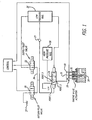
- FIG. 1 a block diagram of an exemplary configuration of a system in accordance with the present invention may be seen.
- the system illustrated in Figure 1 may be used to actuate an intake or an exhaust valve.
- This 2-stage system consists of 2 miniature 2-way digital latching spool valves 20 and 22 coupled to control the position of a 3-way proportional spool valve 24.
- the proportional spool valve controls the flow area into, and out of, a control volume 26.
- This control volume acts on an actuator 28 to regulate the position of the engine valve 30.
- a spring return 32 is utilized for valve closing, though embodiments with hydraulic valve closing may also be used, as shall be subsequently described.
- the 2 miniature 2-way digital latching spool valves 20 and 22 may preferably be identical valves, preferably in accordance with the 2 way valves disclosed in U.S. Patent No. 5,640,987 entitled Digital Two, Three, and Four Way Solenoid Control Valves, issued June 24, 1997, the disclosure of which is incorporated herein by reference.
- Such valves are double solenoid, high speed, magnetically latching spool valves, that as used in the present invention, are operable between two positions. The first position couples a first port to a second port for fluid communication between the two ports, and the second position blocks fluid communication between the first and second ports.
- valves generally of the type disclosed in the above referenced patent are preferred because of their very high speed for good control, and low energy consumption because of such capabilities as their magnetic latching, and the ability to sense completion of actuation, if used, to minimize heating above the already relatively warm environment in which they operate. (See U.S. Patent Nos. 5,720,261 and 5,954,030.)
- valve 20 allows fluid flow from fluid line 34 to a drain line or reservoir 37 (at a relatively low pressure, such as atmospheric pressure) when in its first position, and blocks fluid flow from fluid line 34 to the drain 37 when in its second position.
- Valve 22 allows fluid flow from a low pressure rail 36 to the fluid line 34 when in its first position, and blocks fluid flow from the low pressure rail 36 to the fluid line 34 when in its second position.
- Check valve 23 is optional, and is normally closed, as the differential pressure on the check valve normally will not be in a direction to open the valve. Its presence however, will help damp transient pressure fluctuations and recover energy in the pressure fluctuations.
- the proportional spool valve includes a spool 38 within an internal housing 40 which fits within an external housing assembly (not shown) with O-rings in O-ring grooves 42 to separate the regions of ports 1, 2 and 3 from each other and from the ends of the internal housing 40.
- the outer housing assembly in addition to having the associated fluid connections, also includes internal annual grooves adjacent each of the regions identified as ports 1, 2 and 3 in Figure 2, each to act as a manifold region for the holes through the internal housing 40 for fluid communication with a respective one of the inner regions 44, 46 and 48 in the internal housing 40, respectively. Fluid communication from each of the ports to the associated inner region 44, 46 or 48 is provided in the exemplary embodiment not only by through holes 50, but also by cooperatively disposed orthogonal through holes 52 associated with each of the ports.
- the spool 38 is positioned within the internal housing 40 by fluid pressures acting on a piston at the left end of the spool having an effective area A 1 and a piston at the right side of the spool having an effective area of A 2 .
- the spool 38 is shown in its extreme left-most position, referred to herein as its first position, as defined by stops on the travel of either the pistons actuating the spool or stops acting on the spool itself. In this position, the spool 38 is blocking fluid communication between ports 2 and 1 and is allowing fluid communication between ports 3 and 2.
- the spool is at its extreme-right position, referred to herein as its second position, fluid communication between ports 1 and 2 is blocked and fluid communication between ports 2 and 3 is enabled.
- a spool valve by way of example in the two miniature, two-way digital latching spool valves 20 and 22 of Figure 1, fluid communication between two adjacent ports will be blocked when the spool is in one position and during the initial motion of the spool toward the other position.
- a flow area between the regions coupled to the two ports is established, that flow area increasing linearly with further motion of the spool. Because that flow area is a peripheral flow area of the full diameter of the spool, once opening starts, a relatively large flow area between the two ports will be opened with only a relatively small further motion of the spool.
- the center land on the spool has a plurality of kerfs 54 equally spaced around each end of the center land, which kerfs begin to open a controlled flow area with spool position prior to the edge of the land on the spool reaching the edge of the land on the internal housing, the normal position for a spool valve flow area starting to be established.
- each end of the center land of the exemplary spool has additional diameters D 1 , D 2 and D 3 , where D 3 is less than D 2 , D 2 is less than D 1 and D 1 is less than D 0 .
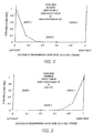
- This provides a non-linear variation in flow area versus spool position during the opening and closing of the fluid communication between adjacent ports, as illustrated in Figures 5 and 6.
- FIGS. 5 and 6 illustrate the flow area between ports 3 and 2, and ports 2 and 1, respectively, versus the position of the spool in the three-way proportional spool valve.
- Figure 5 when the spool is at the left-most position, the flow area between ports 3 and 2 is a maximum, initially decreasing at a relatively high rate for the initial motion of the spool to the right, then decreasing in rate for another part of the motion, then decreasing at a further reduced rate to a substantially zero flow area for the rest of the spool motion, essentially blocking communication between ports 1 and 2 when approximately 40% of the spool motion has been achieved.
- Figure 6 shows the flow area between ports 2 and 1, which is a mirror image of Figure 5.
- the reduction in flow area on the initial valve closing motion of the spool occurs at a high rate with respect to spool position, decreasing in change in flow rate with an increasing position of the spool until the flow area goes to substantially zero when less than half of the spool motion has been achieved, thereby substantially altering the flow area versus spool position characteristic of a conventional spool valve. Also, because the flow area goes to substantially zero before one-half of the maximum spool travel has been achieved, fluid communication between both ports 1 and 2, and ports 2 and 3, is disabled or blocked when the spool is approximately centered within its travel range.
- the substantial blockage between both ports 1 and 2, and ports 2 and 3, occurs whenever the spool's position is anywhere between approximately 40% of its travel and 60% of its travel.
- other shaping of the flow areas, or no shaping may be used if desired, though preferably some shaping will be used to diminish the effect of small errors in spool position in the restricted regions without inhibiting the maximum flow areas when the spool is at its maximum positions.
- fluid in the low pressure rail 36 which may have a pressure, by way of example, of 20 to 50 bar, is coupled to the right side of the three-way proportional spool valve 24 to act on the area A 2 ( Figure 2) of a piston encouraging the spool to its left-most position.
- valve 30 is half open and spool valves 20 and 22 are both closed, then port 2 of the proportional spool valve will be isolated from both ports 1 and 3, so that the fluid in the control volume 26 is trapped, maintaining the valve 30 at its present position.
- the two-way spool valves 20 and 22 are very high speed valves, they may be controlled in such as manner as to rapidly controllably place the spool of the proportional spool valve at any desired location within the extremes of its travel, and thus variably control the flow rate of fluid into or out of the control volume 26.
- valve 30 allows full control of the operating parameters of the valve 30, such as the extent of opening, the timing and duration of opening, the velocity profile of the opening and closing of the valve (which profiles can be different from each other and/or vary with engine operating conditions), and the final valve closing velocity with engine rpm.
- This allows a relatively low velocity valve closing at low engine rpm for low noise operation, while still allowing the closing velocity to be increased with engine rpm, as necessary for higher engine operating speeds.
- the fluid used in the exemplary embodiment in the low pressure rail, the high pressure rail and passed to drain is engine operating oil, though other fluids may be used if desired.
- the flow rates in the control system for valve 30 will vary with various parameters, such as oil viscosity, and thus oil temperature, and the pressure of the low pressure rail and the high pressure rail, operation of the valve control system of Figure 1 must reasonably compensate for such variations.
- these variations may be reasonably modeled so that the control system as shown in Figure 1 can reasonably vary operating durations of valves 20 and 22 to at least approximate the desired profile of the proportional valve spool position with engine crankshaft angle, given the existing engine operating parameters (speed, engine load, fuel temperature, air temperature, engine oil temperature, atmospheric pressure, etc.).
- a small Hall effect sensor 58 is positioned adjacent actuator 28 for the valve 30 so as to provide a feedback signal to the controller.
- valve motion during a valve operating cycle may be monitored and used to control the operation of the valves 20 and 22 for that valve operating cycle, and/or to make corrections in the next valve operating cycle to more accurately achieve optimum valve operation for that valve operating cycle.
- more optimum operation may be determined in any of various ways, including better compliance to a predetermined valve position profile versus engine crank angle as predetermined for the then existing engine operating conditions and ambient conditions, or as determined by the effect of incremental changes on one or more engine performance characteristics for the change in valve operation just made, or a combination of both.
- a sensor such as a position sensor (Hall effect sensor or other position sensor) may be used on only one of the valves, or on both valves, the sum of the signals providing a better average indication of the position profile of the two valves and the difference in the signals providing fault detection, such as a sticky valve. While a position sensor(s) is preferred, other types of sensors could be used, such as a velocity sensor, as the integration times to convert to position are short.
- control valve 22 is actuated to couple line 34 to the low pressure rail 36 and control valve 20 is actuated to decouple line 34 from the drain 37 to bring the spool 38 to the stop at the position shown schematically in Figure 1.
- This provides predetermined spool and pilot valve starting points for each valve operating cycle so that errors in the spool valve position do not accumulate, valve operating cycle to valve operating cycle.
- a sensor may also be used to sense the position of the proportional spool valve spool 38, though this is not preferred.
- the two miniature latching valves 20 and 22 (sometimes-referred to herein as pilot valves) control the position of the proportional valve 24.
- the supply pilot valve 22 allows fluid to flow between a low-pressure rail 32 (approximately 20-50 bar) and a first piston used to move the proportional 3-way valve.
- the vent pilot valve 20 will allow fluid to flow from the piston to a vent at atmospheric pressure.
- the position of the proportional valve can be changed quickly and accurately.
- the position of the proportional valve can be infinitely varied throughout 3 flow states noted in Figures 5 and 6, namely:
- An exemplary valve event may be described as follows. Initially the supply pilot valve 22 is open and the vent pilot valve 20 is closed (as illustrated in Figure 1). This keeps the proportional valve spool in the venting (right-most) position (State 3, Figures 5 & 6). Specifically, the flow area between engine valve actuation piston control volume 26 and vent 37 is at a maximum (state 3, Figure 6) and the area between engine valve actuation piston control volume and the high-pressure rail is closed (state 3, Figure 5). As a result, the engine valve is forced closed against its seat by the return spring 32.
- the supply pilot valve 22 is opened and the vent pilot valve 20 is closed. This allows fluid to flow from the control volume of the proportional spool valve to vent. As a result, the proportional spool begins to move from state 3.
- the vent pilot valve 20 is left open long enough for the proportional spool to pass through state 2 and into state 1. However, the proportional valve is only allowed to travel until just a small flow area in the low gain region of state 1 is open between the high-pressure rail ( Figure 5) and engine valve actuation piston control volume 26. This results in a slow take-off of the engine valve. The speed of this take-off will vary depending on where the proportional valve is stopped.
- vent pilot valve 20 is opened once again so that the proportional spool moves to a position that opens a larger flow area between the high pressure rail and the engine valve actuation piston's control volume. This results in a rapid opening of the engine valve after the initial slow takeoff.
- the proportional spool will be moved to state 2 in which the control volume above the engine valve is hydraulically locked. This is achieved by closing the vent pilot valve 20 and opening the supply pilot valve 22 for the required amount of time. The engine valve will stay in this position until it is commanded to return. At this point the kinetic energy in the engine valve is fully converted into potential energy of the fluid in the control volume and the engine valve return spring. This trade off between kinetic and potential energy occurs several times while the control volume is hydraulically locked, which can result in a slight oscillation of the engine valve position. To reduce this effect and to recover some of the kinetic energy in the proportional valve spool, a check valve could also be placed between the control volume 26 of the engine valve actuator and the high-pressure rail 56 in order to damp out any high pressure spikes that may occur during operation.
- the supply pilot valve 22 will be opened again long enough to move the proportional valve to the high gain region of state 3, and then closed, at least before vent pilot valve 20 is again opened.
- the flow area between the engine valve control volume 26 and vent 37 is a maximum. Therefore, the engine valve will accelerate very quickly toward its seat via the stored energy in the valve spring.
- the flow area that connects the engine valve control volume 26 and vent 37 must be restricted. This can be achieved by once again opening the vent pilot valve 20 for a short period to reposition the proportional valve to a low gain in state 3. This seating velocity will change depending on where the proportional valve is stopped in this region.
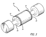
- an engine valve actuator consisting of two concentric pistons was used, as illustrated in Figure 7.
- the large piston boost piston 60
- boost piston 60 is used only initially to achieve peak velocities before reaching a mechanical stop, while the remainder of the stroke is accomplished using a smaller telescoping piston (drive piston 62).
- drive piston 62 a smaller telescoping piston
- boost piston 60 when the engine valve, particularly an exhaust valve, initiates lift from its seat, in-cylinder pressure remains substantial.
- maximum engine valve acceleration is also required at this time.
- a greater force is needed to actuate the engine valve through the beginning of its stroke while a much lower force is required for the remainder of the stroke.
- the present invention system does not rely on using the two concentric piston design, as it will also function if just one actuator is used.
- the two concentric piston design requires less fluid from the high pressure rail for each valve cycle, and thus requires less energy for valve operation.
- valve actuator comprises a piston 64 having a cross-sectional area A 1 on a piston rod 66 having a cross-sectional area A 2 .
- Chamber 68 is permanently coupled to the high pressure rail, and chamber 70 is switchable by the proportional valve between the high pressure rail and the vent. Consequently, the maximum valve opening force is equal to the pressure of the high pressure rail times A 2 and the maximum valve closing force is equal to the pressure of the high pressure rail times A 1 -A 2 . Because of the functional relationship between spring force and stroke, one can achieve essentially the same valve dynamics as a hydraulically returned valve with a smaller diameter actuator.
- the spring closing force is at a minimum when one desires a large opening force for maximum acceleration against peak cylinder pressure.
- hydraulic return the closing force of a hydraulically returned engine valve is constant and therefore will be higher than that of a spring when the valve is seated. Therefore, the force characteristic of a mechanical spring is more desirable for returning the engine valves than a single piston return mechanism.
- the hydraulically returned system can also be constructed using a closed center 4-way proportional valve (Figure 9). Like the closed center 3-way proportional valve, its position can also be infinitely varied throughout 3 flow states.
- the proportional valve uses hydraulic force to oppose the pressure in its control volume.
- the proportional valve can also use a spring to supply part or all of the opposing force.
- Any of the 3-way proportional valve systems can take advantage of the recovery systems known in the art.
- the low-pressure rail used for actuating the 3 or 4 way proportional valve can be used for the low-pressure source of the recovery system if that system is implemented.
- the present invention has many advantages for both diesel and gasoline engines, as well as similar engines powered with alternate fuels. These advantages include:
- the proportional 3 or 4 way valve has low gain flow regions for fine control at valve take-off and seating. It also has high gain flow regions for maximum flow allowing increased speed of the engine valve so that airflow into the engine cylinders can be maximized.
- the system can allow the engine valve profile to be non-symmetric.
- the system is capable of an infinitely varying the slew rate of the engine valve independent of rail pressure.
- the system does not require a slow take-off and landing. Specifically, the valve can begin opening with maximum acceleration or seat at maximum velocity if desired.
- the system does not need a lash adjustment system, specifically:
- the system can compensate for varying working fluid viscosity due to temperature, age, etc.
- the system can optimize the amount time at which air is metered into the engine cylinder thus optimizing the combustion event at the full spectrum of engine operating conditions resulting in:
- the system can be operated in such a way that engine braking will result, specifically by shutting off the injector during braking and opening the exhaust valve at the top of the compression stroke to dissipate the compression energy.
- the engine cycle can be varied to allow for:
- the system will operate more efficiently with a sequentially apportioned pump.
- the low-pressure rail can be replaced with an accumulator that is supplied by the return flow of the engine valve actuator.
- the throttle body can be eliminated.
- Operation of the turbo can be optimized at all engine operating conditions.
- This 2-stage system has the capability of satisfactorily controlling engine valves at very high engine speeds (from idle speeds to 10,000 RPM).
- the critical regions of valve take-off and seating can be controlled with accuracy and precision while providing the features of infinitely variable valve timing, duration and lift.
- the system also has the capability of significantly increasing the amount of air that can be supplied to an engine's cylinders throughout the full range of engine speed by adjusting valve timing and duration to maximize the dynamic effects of flow into and out of the combustion chamber at all engine speeds.
Landscapes
- Engineering & Computer Science (AREA)
- Mechanical Engineering (AREA)
- General Engineering & Computer Science (AREA)
- Valve Device For Special Equipments (AREA)
- Magnetically Actuated Valves (AREA)
- Fluid-Pressure Circuits (AREA)
Claims (14)
- Vorrichtung, die ausgelegt ist zum Betätigen eines Motorventils (30), umfassend:einen hydraulischen Aktuator (28), der betätigbar ist, um über den Druck eines auf den hydraulischen Aktuator (28) wirkenden Fluids wahlweise das Motorventil (30) in Richtung einer offenen Stellung des Motorventils zu bewegen;ein Proportionalventil (24), das ein Ventilelement (38) hat, das bewegbar ist zwischen einer ersten Stellung, bei welcher das Proportionalventil (24) ausgelegt ist, um eine Fluidquelle unter einem ersten Druck (56) mit dem hydraulischen Aktuator (28) zu koppeln und einer zweiten Stellung, bei welcher das Proportionalventil (24) ausgelegt ist, um den hydraulischen Aktuator (28) mit einem Fluidreservoir unter einem zweiten Druck (37) zu koppeln, wobei der zweite Druck kleiner ist als der erste Druck,elektrische gesteuerte Ventilausrüstungen (20, 22), die hydraulisch die Stellung des Ventilelements steuern;eine Rückführung (32) für das Motorventil, die betätigbar ist, um das Motorventil (30) in eine geschlossene Stellung rückzuführen;dadurch gekennzeichnet, daß das Proportionalventil (24) eine dritte Stellung zwischen der ersten Stellung und der zweiten Stellung hat, bei welcher das Proportionalventil (24) eine fluidmäßige Verbindung zwischen dem hydraulischen Aktuator (28) und der Fluidquelle unter dem ersten Druck (56) blockiert, und auch eine fluidmäßige Verbindung zwischen dem hydraulischen Aktuator (28) und dem Fluidreservoir unter dem zweiten Druck (37) blockiert;
das Proportionalventil (24) derart ausgestaltet ist, daß es einen Fluidströmungsquerschnitt vorsieht, der ausgelegt ist, um die Fluidquelle (56) mit dem hydraulischen Aktuator (28) zu koppeln, wobei der Fluidströmungsquerschnitt sich nicht-linear mit Änderung der Stellung des Ventilelements ändert, wenn sich das Ventilelement (38) von der dritten Stellung in die erste Stellung bewegt. - Vorrichtung nach Anspruch 1, bei welcher die Rückführung für das Motorventil eine mechanische Rückhohlfeder (32) umfaßt.
- Vorrichtung nach Anspruch 1, bei welcher die Rückführung für das Motorventil eine hydraulische Rückführung umfaßt.
- Vorrichtung nach Anspruch 1, bei welcher das Proportionalventil ein zentral geschlossenes Proportionalventil ist.
- Vorrichtung nach Anspruch 1, bei welcher das Proportionalventil (24) ein zentral geschlossenes Dreiwegproportionalventil ist.
- Vorrichtung nach Anspruch 1, bei welcher das Proportionalventil (24) ein zentral geschlossenes Vierwegproportionalventil ist.
- Vorrichtung nach Anspruch 1, bei welcher die elektrisch gesteuerte Ventilausrüstung zwei Zweiwegventile (20, 22) umfaßt.
- Vorrichtung nach Anspruch 1, bei welcher die elektrisch gesteuerte Ventilausrüstung, welche hydraulisch die Stellung des Ventilelements steuert, eine elektrisch gesteuerte Ventilausrüstung umfaßt, um steuerbar eine erste hydraulische Kraft auszuüben, um das Ventilelement in eine Richtung zu bewegen und um steuerbar die erste hydraulische Kraft aufzuheben, so daß eine zweite hydraulische Kraft, die geringer ist als die erste hydraulische Kraft, das Ventilelement in eine entgegengesetzte Richtung bewegen kann.
- Vorrichtung nach Anspruch 1, bei welcher die elektrisch gesteuerte Ventilausrüstung, welche hydraulisch die Stellung des Ventilelements steuert, eine elektrisch gesteuerte Ventilausrüstung umfaßt, um steuerbar eine erste hydraulische Kraft auszuüben, um das Ventilelement in eine Richtung zu bewegen und um steuerbar die erste hydraulische Kraft aufzuheben, so daß eine Rückholfeder das Ventilelement in eine entgegengesetzte Richtung bewegen kann.
- Vorrichtung nach Anspruch 1, bei welcher die elektrisch gesteuerte Ventilausrüstung zwei Zweiwegedoppelsolenoidspulenventile umfaßt.
- Vorrichtung nach Anspruch 1, bei welcher die elektrisch gesteuerte Ventilausrüstung zwei Zweiwege-, sperrbare Magnetspulenventile umfaßt.
- Vorrichtung nach Anspruch 1, bei welcher das Proportionalventil (24) auch derart ausgestaltet ist, daß es einen Fluidströmungsquerschnitt vorsieht, der ausgelegt ist, um das Fluidreservoir (37) mit dem hydraulischen Aktuator (28) zu koppeln, wobei der Fluidströmungsquerschnitt sich nicht-linear mit der Änderung der Stellung des Ventilelements ändert, wenn das Ventilelement (28) sich von der dritten Stellung in die zweite Stellung bewegt.
- Vorrichtung nach Anspruch 12, bei welcher die nicht-linearen Änderungen des Fluidströmungsquerschnitts bei Änderung der Ventilstellung eine Abnahme der zeitlichen Änderung des Fluidströmungsquerschnitts mit der Stellung des Ventilelements aufweisen, wenn das Ventilelement aus sowohl der ersten wie auch der zweiten Stellung in Richtung der dritten Stellung fortschreitet.
- Vorrichtung nach Anspruch 1, bei welcher:die Rückführung für das Motorventil einen zweiten hydraulischen Aktuator aufweist, der betätigbar ist, um über den Druck eines auf den zweiten hydraulischen Aktuator wirkenden Fluids wahlweise das Motorventil in Richtung einer geschlossenen Stellung des Motorventils zu bewegen;das Ventilelement des Proportionalventils auch in eine vierte Stellung bewegbar ist, bei welcher das Proportionalventil ausgelegt ist, um die Fluidquelle mit dem zweiten hydraulischen Aktuator zu koppeln, um das Motorventil in Richtung der geschlossenen Stellung des Motorventils zu bewegen, wobei das Proportionalventil das Fluidreservoir mit dem zweiten hydraulischen Aktuator koppelt, wenn sich das Ventilelement in der ersten, zweiten oder dritten Stellung befindet;die elektrisch gesteuerte Ventilausrüstung die Stellung des Ventilelements zwischen der ersten bis vierten Stellung hydraulisch steuert.
Applications Claiming Priority (3)
| Application Number | Priority Date | Filing Date | Title |
|---|---|---|---|
| US72948700A | 2000-12-04 | 2000-12-04 | |
| US729487 | 2000-12-04 | ||
| PCT/US2001/046686 WO2002046582A2 (en) | 2000-12-04 | 2001-11-30 | Hydraulic valve actuation systems and methods |
Publications (2)
| Publication Number | Publication Date |
|---|---|
| EP1409853A2 EP1409853A2 (de) | 2004-04-21 |
| EP1409853B1 true EP1409853B1 (de) | 2006-04-19 |
Family
ID=24931263
Family Applications (1)
| Application Number | Title | Priority Date | Filing Date |
|---|---|---|---|
| EP01995378A Expired - Lifetime EP1409853B1 (de) | 2000-12-04 | 2001-11-30 | Vorichtungen und verfahren zur hydraulischen betätigung von einem ventil |
Country Status (6)
| Country | Link |
|---|---|
| US (1) | US20020157623A1 (de) |
| EP (1) | EP1409853B1 (de) |
| JP (1) | JP2004515681A (de) |
| AU (1) | AU2002225937A1 (de) |
| DE (1) | DE60118984T2 (de) |
| WO (1) | WO2002046582A2 (de) |
Families Citing this family (30)
| Publication number | Priority date | Publication date | Assignee | Title |
|---|---|---|---|---|
| US8215292B2 (en) | 1996-07-17 | 2012-07-10 | Bryant Clyde C | Internal combustion engine and working cycle |
| US6739293B2 (en) * | 2000-12-04 | 2004-05-25 | Sturman Industries, Inc. | Hydraulic valve actuation systems and methods |
| ITBO20010092A1 (it) * | 2001-02-20 | 2002-08-20 | Magneti Marelli Spa | Dispositivo elettroidraulico per l'azionamento delle valvole di un motore a scoppio |
| US20030140876A1 (en) * | 2002-01-30 | 2003-07-31 | Zhou Yang | Engine valve actuation system and method using reduced pressure common rail and dedicated engine valve |
| US6732685B2 (en) * | 2002-02-04 | 2004-05-11 | Caterpillar Inc | Engine valve actuator |
| US7347171B2 (en) * | 2002-02-04 | 2008-03-25 | Caterpillar Inc. | Engine valve actuator providing Miller cycle benefits |
| US7069887B2 (en) * | 2002-05-14 | 2006-07-04 | Caterpillar Inc. | Engine valve actuation system |
| US6941909B2 (en) * | 2003-06-10 | 2005-09-13 | Caterpillar Inc | System and method for actuating an engine valve |
| US7004122B2 (en) * | 2002-05-14 | 2006-02-28 | Caterpillar Inc | Engine valve actuation system |
| GB2391288B (en) | 2002-07-30 | 2004-12-22 | Lotus Car | An electrically operated valve for controlling flow of hydraulic fluid |
| DE10310300A1 (de) * | 2003-03-10 | 2004-09-23 | Robert Bosch Gmbh | Verfahren zum Betreiben eines hydraulischen Aktors, insbesondere eines Gaswechselventils einer Brennkraftmaschine |
| US6912458B2 (en) * | 2003-06-25 | 2005-06-28 | Caterpillar Inc | Variable valve actuation control for operation at altitude |
| US7341028B2 (en) | 2004-03-15 | 2008-03-11 | Sturman Industries, Inc. | Hydraulic valve actuation systems and methods to provide multiple lifts for one or more engine air valves |
| US7421981B2 (en) * | 2004-03-17 | 2008-09-09 | Ricardo, Inc. | Modulated combined lubrication and control pressure system for two-stroke/four-stroke switching |
| US7387095B2 (en) | 2004-04-08 | 2008-06-17 | Sturman Industries, Inc. | Hydraulic valve actuation systems and methods to provide variable lift for one or more engine air valves |
| JP2006029247A (ja) * | 2004-07-20 | 2006-02-02 | Denso Corp | エンジンの停止始動制御装置 |
| JP4583229B2 (ja) * | 2005-04-19 | 2010-11-17 | 本田技研工業株式会社 | 内燃機関の動弁装置 |
| US7555998B2 (en) * | 2005-12-01 | 2009-07-07 | Jacobs Vehicle Systems, Inc. | System and method for hydraulic valve actuation |
| EP2063075A1 (de) | 2007-11-23 | 2009-05-27 | EMPA Eidgenössische Materialprüfungs- und Forschungsanstalt | Fluid betriebener Ventiltrieb |
| GB2466513A (en) * | 2008-12-29 | 2010-06-30 | Mehdi Ansari | Computer controlled hydraulic and mechanical system for variable valve timing, valve lift and valve opening duration in car engines |
| US8412441B1 (en) | 2009-09-09 | 2013-04-02 | Sturman Digital Systems, Llc | Mixed cycle compression ignition engines and methods |
| FI20095970L (fi) * | 2009-09-21 | 2011-03-30 | Waertsilae Finland Oy | Järjestely kaasunvaihtoventtiilin käyttämiseksi |
| US8689769B2 (en) * | 2010-05-12 | 2014-04-08 | Caterpillar Inc. | Compression-braking system |
| US8939173B2 (en) * | 2010-07-14 | 2015-01-27 | Mac Valves, Inc. | Stepper motor operated balanced flow control valve |
| JP5781331B2 (ja) * | 2011-02-28 | 2015-09-24 | 三菱重工業株式会社 | 内燃機関の動弁装置 |
| JP5781330B2 (ja) * | 2011-02-28 | 2015-09-24 | 三菱重工業株式会社 | 内燃機関の動弁装置 |
| KR101518907B1 (ko) * | 2013-12-17 | 2015-05-11 | 현대자동차 주식회사 | 오일 공급 유로 |
| DE102016002051A1 (de) * | 2016-02-22 | 2017-08-24 | GM Global Technology Operations LLC (n. d. Gesetzen des Staates Delaware) | Kraftfahrzeug-Antriebsstrang-Steuerung |
| US10232841B2 (en) * | 2016-11-18 | 2019-03-19 | Ford Global Technologies, Llc | Methods and system for improving response of a hybrid vehicle |
| DE102019201043A1 (de) * | 2019-01-28 | 2020-07-30 | Sms Group Gmbh | Steuerung hydraulischer Stellzylinder in Walzgerüsten |
Family Cites Families (5)
| Publication number | Priority date | Publication date | Assignee | Title |
|---|---|---|---|---|
| DE1292493B (de) * | 1964-04-16 | 1969-04-10 | Frisch Geb Kg Eisenwerk | Hydraulische Steuervorrichtung fuer einen in einem Zylinder verschiebbaren Arbeitskolben |
| US5248123A (en) * | 1991-12-11 | 1993-09-28 | North American Philips Corporation | Pilot operated hydraulic valve actuator |
| US5193584A (en) * | 1992-02-20 | 1993-03-16 | Sauer Inc. | Spool valve and method of making the same |
| US5640987A (en) * | 1994-04-05 | 1997-06-24 | Sturman; Oded E. | Digital two, three, and four way solenoid control valves |
| DE19543080C2 (de) * | 1995-11-18 | 1999-10-28 | Man B & W Diesel Ag | Vorrichtung zur Steuerung von Ventilen einer Brennkraftmaschine, insbesondere des Gaszufuhrventils eines Gasmotors |
-
2001
- 2001-11-30 AU AU2002225937A patent/AU2002225937A1/en not_active Abandoned
- 2001-11-30 WO PCT/US2001/046686 patent/WO2002046582A2/en active IP Right Grant
- 2001-11-30 DE DE60118984T patent/DE60118984T2/de not_active Expired - Lifetime
- 2001-11-30 JP JP2002548287A patent/JP2004515681A/ja active Pending
- 2001-11-30 EP EP01995378A patent/EP1409853B1/de not_active Expired - Lifetime
-
2002
- 2002-03-25 US US10/108,246 patent/US20020157623A1/en not_active Abandoned
Also Published As
| Publication number | Publication date |
|---|---|
| EP1409853A2 (de) | 2004-04-21 |
| US20020157623A1 (en) | 2002-10-31 |
| WO2002046582A3 (en) | 2003-01-16 |
| JP2004515681A (ja) | 2004-05-27 |
| WO2002046582A2 (en) | 2002-06-13 |
| DE60118984D1 (de) | 2006-05-24 |
| DE60118984T2 (de) | 2007-01-11 |
| AU2002225937A1 (en) | 2002-06-18 |
Similar Documents
| Publication | Publication Date | Title |
|---|---|---|
| EP1409853B1 (de) | Vorichtungen und verfahren zur hydraulischen betätigung von einem ventil | |
| US6739293B2 (en) | Hydraulic valve actuation systems and methods | |
| US4206728A (en) | Hydraulic valve actuator system | |
| US4716863A (en) | Internal combustion engine valve actuation system | |
| US6925976B2 (en) | Modal variable valve actuation system for internal combustion engine and method for operating the same | |
| US5937807A (en) | Early exhaust valve opening control system and method | |
| CN106014522B (zh) | 可变阀致动器 | |
| US5002022A (en) | Valve control system with a variable timing hydraulic link | |
| EP1936132B1 (de) | Verbrennungsmotor mit Einlassventilen mit variabler Betätigung und einem stiefelartigen Hubprofil mit einem Profilteil mit konstantem Hub | |
| US7258088B2 (en) | Engine valve actuation system | |
| Urata et al. | A study of vehicle equipped with non-throttling SI engine with early intake valve closing mechanism | |
| US7730858B2 (en) | Hydraulic valve actuation systems and methods to provide variable lift for one or more engine air valves | |
| US7441519B2 (en) | Engine valve actuation system | |
| US6964270B2 (en) | Dual mode EGR valve | |
| EP1464794B1 (de) | Ventilaktuatoranordnung mit zwei hydraulischen rückkopplungsschleifen. | |
| US20040060529A1 (en) | Hydraulic valve actuation system | |
| US6237559B1 (en) | Cylinder deactivation via exhaust valve deactivation and intake cam retard | |
| US6907851B2 (en) | Engine valve actuation system | |
| US5058857A (en) | Solenoid operated valve assembly | |
| EP1408220B1 (de) | System und Verfahren zur Steuerung einer Brennkraftmaschine | |
| US8127734B2 (en) | Internal combustion engine having guillotine sliding valve | |
| US5806476A (en) | Valve mechanism in an internal combustion engine | |
| GB2443690A (en) | Retractable cam system for an 8-stroke and 4-stroke cycle change engine | |
| US20040065285A1 (en) | Variable engine valve actuator | |
| EP0835995A2 (de) | Brennkraftmaschine mit Einlasskanal mit veränderlichem Volumen |
Legal Events
| Date | Code | Title | Description |
|---|---|---|---|
| PUAI | Public reference made under article 153(3) epc to a published international application that has entered the european phase |
Free format text: ORIGINAL CODE: 0009012 |
|
| 17P | Request for examination filed |
Effective date: 20030721 |
|
| AK | Designated contracting states |
Kind code of ref document: A2 Designated state(s): AT BE CH CY DE DK ES FI FR GB GR IE IT LI LU MC NL PT SE TR |
|
| RIN1 | Information on inventor provided before grant (corrected) |
Inventor name: BABBITT, GUY, ROBERT Inventor name: TURNER, CHRISTOPHER, WAYNE Inventor name: RAIMAO, MIGUEL, ANGELO |
|
| RBV | Designated contracting states (corrected) |
Designated state(s): DE FR GB SE |
|
| 17Q | First examination report despatched |
Effective date: 20041112 |
|
| GRAP | Despatch of communication of intention to grant a patent |
Free format text: ORIGINAL CODE: EPIDOSNIGR1 |
|
| GRAS | Grant fee paid |
Free format text: ORIGINAL CODE: EPIDOSNIGR3 |
|
| GRAA | (expected) grant |
Free format text: ORIGINAL CODE: 0009210 |
|
| AK | Designated contracting states |
Kind code of ref document: B1 Designated state(s): DE FR GB SE |
|
| REG | Reference to a national code |
Ref country code: GB Ref legal event code: FG4D |
|
| REF | Corresponds to: |
Ref document number: 60118984 Country of ref document: DE Date of ref document: 20060524 Kind code of ref document: P |
|
| REG | Reference to a national code |
Ref country code: SE Ref legal event code: TRGR |
|
| ET | Fr: translation filed | ||
| PLBE | No opposition filed within time limit |
Free format text: ORIGINAL CODE: 0009261 |
|
| STAA | Information on the status of an ep patent application or granted ep patent |
Free format text: STATUS: NO OPPOSITION FILED WITHIN TIME LIMIT |
|
| 26N | No opposition filed |
Effective date: 20070122 |
|
| PGFP | Annual fee paid to national office [announced via postgrant information from national office to epo] |
Ref country code: GB Payment date: 20101223 Year of fee payment: 10 |
|
| PGFP | Annual fee paid to national office [announced via postgrant information from national office to epo] |
Ref country code: FR Payment date: 20111213 Year of fee payment: 11 |
|
| PGFP | Annual fee paid to national office [announced via postgrant information from national office to epo] |
Ref country code: SE Payment date: 20121128 Year of fee payment: 12 |
|
| GBPC | Gb: european patent ceased through non-payment of renewal fee |
Effective date: 20121130 |
|
| REG | Reference to a national code |
Ref country code: FR Ref legal event code: ST Effective date: 20130731 |
|
| PG25 | Lapsed in a contracting state [announced via postgrant information from national office to epo] |
Ref country code: GB Free format text: LAPSE BECAUSE OF NON-PAYMENT OF DUE FEES Effective date: 20121130 Ref country code: FR Free format text: LAPSE BECAUSE OF NON-PAYMENT OF DUE FEES Effective date: 20121130 |
|
| REG | Reference to a national code |
Ref country code: SE Ref legal event code: EUG |
|
| PG25 | Lapsed in a contracting state [announced via postgrant information from national office to epo] |
Ref country code: SE Free format text: LAPSE BECAUSE OF NON-PAYMENT OF DUE FEES Effective date: 20131201 |
|
| PGFP | Annual fee paid to national office [announced via postgrant information from national office to epo] |
Ref country code: DE Payment date: 20141211 Year of fee payment: 14 |
|
| REG | Reference to a national code |
Ref country code: DE Ref legal event code: R119 Ref document number: 60118984 Country of ref document: DE |
|
| PG25 | Lapsed in a contracting state [announced via postgrant information from national office to epo] |
Ref country code: DE Free format text: LAPSE BECAUSE OF NON-PAYMENT OF DUE FEES Effective date: 20160601 |