EP1409185B1 - Gewindeformer oder -bohrer - Google Patents
Gewindeformer oder -bohrer Download PDFInfo
- Publication number
- EP1409185B1 EP1409185B1 EP02764705A EP02764705A EP1409185B1 EP 1409185 B1 EP1409185 B1 EP 1409185B1 EP 02764705 A EP02764705 A EP 02764705A EP 02764705 A EP02764705 A EP 02764705A EP 1409185 B1 EP1409185 B1 EP 1409185B1
- Authority
- EP
- European Patent Office
- Prior art keywords
- shaft
- profile element
- tap
- thread forming
- screw
- Prior art date
- Legal status (The legal status is an assumption and is not a legal conclusion. Google has not performed a legal analysis and makes no representation as to the accuracy of the status listed.)
- Expired - Lifetime
Links
Images

Classifications
-
- B—PERFORMING OPERATIONS; TRANSPORTING
- B23—MACHINE TOOLS; METAL-WORKING NOT OTHERWISE PROVIDED FOR
- B23G—THREAD CUTTING; WORKING OF SCREWS, BOLT HEADS, OR NUTS, IN CONJUNCTION THEREWITH
- B23G7/00—Forming thread by means of tools similar both in form and in manner of use to thread-cutting tools, but without removing any material
- B23G7/02—Tools for this purpose
-
- B—PERFORMING OPERATIONS; TRANSPORTING
- B23—MACHINE TOOLS; METAL-WORKING NOT OTHERWISE PROVIDED FOR
- B23G—THREAD CUTTING; WORKING OF SCREWS, BOLT HEADS, OR NUTS, IN CONJUNCTION THEREWITH
- B23G5/00—Thread-cutting tools; Die-heads
- B23G5/02—Thread-cutting tools; Die-heads without means for adjustment
- B23G5/06—Taps
-
- B—PERFORMING OPERATIONS; TRANSPORTING
- B23—MACHINE TOOLS; METAL-WORKING NOT OTHERWISE PROVIDED FOR
- B23G—THREAD CUTTING; WORKING OF SCREWS, BOLT HEADS, OR NUTS, IN CONJUNCTION THEREWITH
- B23G2200/00—Details of threading tools
- B23G2200/02—Tools in which the shank and the cutting part are made from different materials or from separate components
Definitions
- the invention relates to a thread former or drill according to the preamble of Patent claim 1.
- a thread former is from document GB-A-1209196.
- Thread formers are also geometrically from a bolt derived. However, they do not chop up a material, but merely displace it. The Workpiece is therefore pre-drilled with the mean flank diameter. Of the Thread former has at the top a rising profile, which is the material increasingly displaced.
- a thread former has become known with a cylindrical Clamping shank and a shaping area deviating from the circular shape, polygonal cross section and with the thread to be produced corresponding thread furrows on the outer circumference.
- corners of the shaping area are cylindrical strips of particularly hard and wear-resistant material soldered into corresponding, axially extending grooves, which have a thread grooves adapted profiling on the outer circumference.
- Taps have the same thread profile as taps However, in their profile section a polygonal cross-section with, for example three or six "corners".
- the profile section of thread formers and drills has a first forming Area on which essentially the thread is made and a subsequent leadership section. This serves to guide the tool when Turn back from the hole after completion of the internal thread.
- Thread formers and drills are relatively expensive to manufacture and are under Circumstances of a high quality material. After wear or damage the tool is no longer usable.
- the invention has for its object to a thread former or drill to create that produced with a lesser amount of material and manufacturing can be.
- the forming or cutting profile section is as formed separate profile element that except an inlet or gate taper has at least two full profiles and by means of a fastening device can be mounted centric and non-rotatable on the shaft.
- the profile element may be plate-shaped, or have a short axial length; except the inlet or gate cone, it has relatively few full profiles on, for example two to four.
- the shank for the tool according to the invention can in a conventional manner and conventional dimensions of a highly resilient material, in particular be made of a suitable steel. He needs wear of the profile element not to be thrown away, but can be reused frequently.
- the invention also makes it possible to provide a plurality of different ones Profile elements with different diameter, different pitch and so on, which can each be connected to a unified body.
- the profile element therefore only needs to consist of a suitable hard material. As a result, the material usage is significantly lower than with conventional Tools.
- the projections and depressions have complementary lateral to the axis of the Shank or the profile element inclined surfaces, for the purpose of centering and torque transmission engaged. These surfaces can plan or be formed spherical. Preferably, only the mentioned surfaces are engaged, which means that the end faces of profile element and shank a distance have each other when the profile element is attached to the shaft.
- the surfaces are formed on ribs or grooves which are crosswise are arranged radially, with the center of the cross on the axis of Shank or the profile element is located.
- the edges of the ribs and grooves may have a chamfer.
- the profile element can be a hard metal, but also high-speed steel, Ceramic, or other known material used. It understands itself, that the outer diameter of the shaft at the thread former, at least must be slightly smaller than the core diameter of the thread to be created.
- shank can certainly be used for profile elements for producing different Thread sizes are used.
- an attachment of the separate profile element on the shaft there are various possibilities conceivable, an attachment of the separate profile element on the shaft.
- the profile element by means of a screw in an axial Tapped hole is attached to the shaft.
- the profile element has accordingly a central bore, wherein the screw z.
- B. a conical section having, with a conical countersinking of the bore of the profile element interacts. The screw makes no contribution to torque transmission from the shaft to the workpiece.
- a threaded stem may be formed on the stem, either with a threaded bore of the profile element cooperates, or it is a nut provided, which is screwed onto the pin for attachment of the profile element on the shaft.
- the profile element can also be soldered to the shaft. In this case is However, the interchangeability makes it difficult, since the profile element is heated first must when it should be removed from the shaft.
- a single profile element is centric on Shaft attached.
- Another solution according to the invention provides that two or more identical plate-shaped separate shape profiles on the front side of the shaft be fastened non-rotatably.
- the shape profiles have as well as the above described profiles in the sections projecting beyond the shaft Threaded profiles on to produce the internal thread.
- Such a tool is a thread rolling tool comparable to the creation of internal thread with the Exception that in the invention, the "roles" non-rotatably attached to the shaft are.
- the last tool described is especially suitable as a mold.
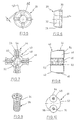
- a Werhzeugschaft 10 is shown, which at one end a clamping section 12 and at the other end a portion 14 for connection with a profile element according to FIG. 4. From the end view of the shaft 10 according to FIG Fig. 2 it can be seen that it has a central threaded bore 16 and cross-shaped arranged ribs 24, wherein the cross of the ribs 24 in its center coincides with the axis of the shaft 10 and the bore 16.
- a plate-shaped shape profile element 20 is shown, which at its Circumference has a Anformkegel and a thread profile (not shown) for Production of an internal thread according to the thread-forming or -formhabilit.
- the circumference of the shape profile element 20 is polygonal, which is not shown in FIG. 4 is. With regard to further details of the profile element 20 is still in connection with the Fign. 5 and 6 received.
- the profile element 20 has a central through hole 22 and on one side Grooves 18 arranged radially in a radial cross-section.
- the grooves 18 are arranged and formed in such a way that that they suitably receive the ribs 24.
- By the positive engagement of ribs 24 and grooves 18 is a positive connection achieved while the remaining surface of the profile element 20 on the remaining surface of the End surface of the shaft 10 either rests flat or preferably a certain Distance from the latter has.
- the projections or ribs 24 are trapezoidal in section, d. H. sloping side surfaces as shown at 25.
- the grooves 18 are complementary Side surfaces provided (not shown), so that when applying the profile element 20th to the shaft end 14 only the surfaces 25 of the ribs 24 and the grooves with each other be engaged, but not the end surfaces of the shaft 10 and profile element 20. Since the radial ribs 24 and the radial grooves 18 perpendicular to each other automatically finds a centering of the element 20 on Shank 10 instead, because the surfaces 25 and the complementary surfaces of the grooves parallel to diameters that are perpendicular to each other. The crossing point the diameter is naturally on the axis of the profile element 20th and shaft 10.
- the surfaces 25 are flat. However, they can also be spherical and in the same way the desired centering and torque transmission effect exhibit.
- the profile element 20 is shown in FIGS. 5 and 6 shown in more detail. you recognizes from the front view of FIG. 5 that the profile element 20 is polygonal, i.e. has four "corners", where the stroke between the corners is indicated by h. It is understood that only in the corners of a thread generation by forming takes place.
- grooves 18 are provided with the corresponding Ripping a shaft, as shown in Fig. 1, in the same way interact, as described in connection with FIGS. 1 to 4 has been explained.
- the Grooves 18 in turn have laterally sloping wall surfaces, with sloping wall surfaces of ribs interact. As can be seen in Fig.
- the profile element 20 a mold cone 28 in a conventional manner and an actual Profile section 30 with two to four gears of a forming thread.
- the bore 22 has a countersink 32 for receiving the cone 34 of the head of the screw 26 of FIG. 9.
- a profile element 40 for a threading tool shown.
- the profile element 40 a tapered gate 42 and a thread cutting portion 44.
- the Tapping section 44 consists of four at 90 ° spaced lugs 46, which are provided at the periphery with corresponding threaded portions, as this at taps is known. Between the lugs 46 are each flutes 48th arranged.
- the profile element 40 has a through bore 50, which on the in Fig. 8 left end has a countersink 52 for receiving the screw head about a screw of Fig. 9.
- the profile element 40 On the shaft, not shown, facing Side, the profile element 40 has a cross-shaped ribs 54, comparable the ribs 24 of FIG. 3a and 3b.
- the ribs 54 have inclined surfaces 56, the with the inclined surfaces of the grooves of the shaft, not shown, for the profile element 40 interact.
- Fig. 10 at 60 is a shank of a thread forming or cutting tool, such as a shaft according to Fig. 1, shown with its end face 62.
- a thread forming or cutting tool such as a shaft according to Fig. 1, shown with its end face 62.
- On the front side 62 are two profile elements 64 and 66 in the circumferential distance of 180 ° by means of Screws 68 and 70, similar to the screw 26 of FIG. 9, attached.
- the Profile elements 64, 66 for example, resemble the profile element 20 on the circumference Fig. 4, are therefore suitable for thread forming.
- Preferably, even four such profile elements are preferable, so again a polygon similar the results of FIG. 5.
- the generating thread is arranged around the circumference, is also conceivable, the profile elements 64, 66 after previous release by a certain angle to twist to use another profile area that has not yet worn out.
- the profile element 64, 66 are similar in their application so-called indexable inserts.
Landscapes
- Engineering & Computer Science (AREA)
- Mechanical Engineering (AREA)
- Milling Processes (AREA)
- Drilling Tools (AREA)
- Turning (AREA)
- Agricultural Chemicals And Associated Chemicals (AREA)
- Cutting Tools, Boring Holders, And Turrets (AREA)
- Joining Of Building Structures In Genera (AREA)
- Dowels (AREA)
- Forging (AREA)
Description
- Fig. 1
- zeigt die Seitenansicht eines Schaftes für ein erfindungsgemäßes Gewindeformwerkzeug.
- Fig. 2
- zeigt die Stirnansicht des Schaftes nach Fig. 1.
- Fig. 3a
- zeigt die Seitenansicht des Schaftes nach Fig. 2, während Fign. 3b und 3c Einzelheiten wiedergeben.
- Fig. 4
- zeigt die Draufsicht auf ein Profilelement nach der Erfindung.
- Fig. 5
- zeigt vergrößert eine Ansicht eines Profilelements ähnlich Fig. 4.
- Fig. 6
- zeigt die Seitenansicht des Profilelements nach Fig. 5.
- Fig. 7
- zeigt die Rückansicht eines Profilelements nach der Erfmdung für ein Gewindeschneidwerkzeug.
- Fig. 8
- zeigt die Seitenansicht des Profilelements nach Fig. 7.
- Fig. 9
- zeigt eine Schraube zur Befestigung eines der gezeigten Profilelemente an einem Werkzeugschaft, etwa Schaft nach Fig. 1.
- Fig. 10
- zeigt die Vorderansicht einer anderen Ausführungsform eines Profilelements nach der Erfindung.
Claims (13)
- Gewindeformer oder -bohrer mit einem Schaft, der an einem Ende einen Einspannabschnitt und am anderen Ende einen Form- oder Schneidprofilabschnitt aufweist, wobei der Form- oder Schneidprofilabschnitt als separates Profilelement ausgebildet ist, und mittels einer Befestigungsvorrichtung zentrisch und unverdrehbar am Schaft (10) befestigbar ist, dadurch gekennzeichnet, daß das Profilelement (20, 40) eine geringe axiale Länge und außen einen Einlauf- bzw. Anschnittkegel (28, 42) aufweist, dass am Ende des Schaftes (10) und auf der dem Schaft (10) zugekehrten Seite des Profilelements (20, 40) Vorsprünge und/oder Vertiefungen geformt sind, die formschlüssig ineinandergreifen, dass eine automatische Zentrierung des Profilelements (20) am Schaft (10) erfolgt, wenn das Profilelement (20) am Schaft (10) angesetzt wird.
- Gewindeformer oder -bohrer nach Anspruch 1, dadurch gekennzeichnet, daß die Vorsprünge und Vertiefungen komplementäre seitliche zur Achse des Schaftes bzw. des Profilelements geneigte Flächen (25) aufweisen, die zum Zwecke der Zentrierung und Drehmomentübertragung in Eingriff stehen.
- Gewindeformer oder -bohrer nach Anspruch 1, dadurch gekennzeichnet, daß die Flächen plan oder ballig sind.
- Gewindeformer oder -bohrer nach Anspruch 2 oder 3, dadurch gekennzeichnet, daß der formschlüssige Eingriff von Profilelement und Schaft ausschließlich über die Flächen (25) erfolgt.
- Gewindeformer oder -bohrer nach einem der Ansprüche 1 bis 4, dadurch gekennzeichnet, daß die Vorsprünge von Rippen (24, 54) und die Vertiefungen von zu den Rippen komplementären Nuten (18) gebildet sind.
- Gewindeformer oder -bohrer nach Anspruch 2 und 5, dadurch gekennzeichnet, daß die Flächen von Seitenflächen der Vorsprünge und Vertiefungen gebildet sind.
- Gewindeformer oder -bohrer nach Anspruch 6, dadurch gekennzeichnet, daß erste Flächen parallel zu einem ersten Durchmesser verlaufen und zweite Flächen parallel zu einem zweiten Durchmesser verlaufen, der auf dem ersten Durchmesser senkrecht steht, wobei der Kreuzungspunkt der Durchmesser auf der Achse des Profilelements oder des Schaftes liegt.
- Gewindeformer oder -bohrer nach einem der Ansprüche 5 bis 7, dadurch gekennzeichnet, daß die Rippen (24) und Nuten (18) kreuzweise radial angeordnet sind, wobei der Mittelpunkt des Kreuzes auf der Achse des Schaftes (10) bzw. des Profilelements (20) liegt.
- Gewindeformer oder -bohrer nach einem der Ansprüche 1 bis 8, dadurch gekennzeichnet, daß das Profilelement (20, 40) mittels einer zentrischen Schraube (26) in einer axialen Gewindebohrung (16) am Schaft (10) befestigt ist.
- Gewindeformer oder -bohrer nach einem der Ansprüche 1 bis 8, dadurch gekennzeichnet, daß der Schaft einen zentrischen Gewindezapfen aufweist und das Profilelement eine mittige Bohrung, durch welche sich der Gewindezapfen hindurch erstreckt und die mittige Bohrung ein Gewinde aufweist oder eine Mutter vorgesehen ist zur Befestigung des Profilelements auf dem Zapfen.
- Gewindeformer oder -bohrer nach einem der Ansprüche 1 bis 8, dadurch gekennzeichnet, daß das Profilelement am Schaft angelötet ist.
- Gewindeformer oder -bohrer nach einem der Ansprüche 1 bis 11, dadurch gekennzeichnet, daß der Schaft (10) aus einem bezüglich Biegung und Torsion hoch beanspruchbaren Material, insbesondere aus Stahl und das Profilelement (20, 40) aus einem geeigneten Hartstoff besteht.
- Gewindeformer oder -bohrer nach einem der Ansprüche 1 bis 12, dadurch gekennzeichnet, daß das Profilelement insgesamt nicht mehr als zwei bis vier volle Gewindeformgänge aufweist.
Applications Claiming Priority (3)
| Application Number | Priority Date | Filing Date | Title |
|---|---|---|---|
| DE10136293 | 2001-07-25 | ||
| DE10136293A DE10136293B4 (de) | 2001-07-25 | 2001-07-25 | Gewindeformer oder -bohrer |
| PCT/EP2002/007913 WO2003011508A2 (de) | 2001-07-25 | 2002-07-17 | Gewindeformer oder -bohrer |
Publications (3)
| Publication Number | Publication Date |
|---|---|
| EP1409185A2 EP1409185A2 (de) | 2004-04-21 |
| EP1409185B1 true EP1409185B1 (de) | 2005-08-24 |
| EP1409185B2 EP1409185B2 (de) | 2011-06-15 |
Family
ID=7693084
Family Applications (1)
| Application Number | Title | Priority Date | Filing Date |
|---|---|---|---|
| EP02764705A Expired - Lifetime EP1409185B2 (de) | 2001-07-25 | 2002-07-17 | Gewindeformer oder -bohrer |
Country Status (6)
| Country | Link |
|---|---|
| US (1) | US7112143B2 (de) |
| EP (1) | EP1409185B2 (de) |
| AT (1) | ATE302664T1 (de) |
| DE (2) | DE10136293B4 (de) |
| ES (1) | ES2246016T5 (de) |
| WO (1) | WO2003011508A2 (de) |
Families Citing this family (39)
| Publication number | Priority date | Publication date | Assignee | Title |
|---|---|---|---|---|
| DE10304182B4 (de) * | 2003-01-30 | 2007-02-01 | Fette Gmbh | Gewindeformer oder -bohrer |
| DE10338754C5 (de) * | 2003-08-23 | 2016-01-14 | EMUGE-Werk Richard Glimpel GmbH & Co. KG Fabrik für Präzisionswerkzeuge | Werkzeug zur spanlosen Erzeugung eines Gewindes und Verfahren zur Herstellung eines Werkzeugs zur spanlosen Gewindeerzeugung |
| DE102005042410B4 (de) | 2004-09-13 | 2018-10-04 | EMUGE-Werk Richard Glimpel GmbH & Co. KG Fabrik für Präzisionswerkzeuge | Werkzeug und Verfahren zur Erzeugung oder Nachbearbeitung eines Gewindes, insbesondere eines Innengewindes |
| DE102004059264B4 (de) * | 2004-12-08 | 2007-02-22 | EMUGE-Werk Richard Glimpel GmbH & Co. KG Fabrik für Präzisionswerkzeuge | Werkzeug und Verfahren zur Erzeugung eines Gewindes in einem Werkstück |
| US7513320B2 (en) | 2004-12-16 | 2009-04-07 | Tdy Industries, Inc. | Cemented carbide inserts for earth-boring bits |
| DE502005006054D1 (de) * | 2005-01-19 | 2009-01-08 | Fette Gmbh | Gewindeformer oder-bohrer |
| DE102005019426B4 (de) * | 2005-04-25 | 2009-08-06 | EMUGE-Werk Richard Glimpel GmbH & Co. KG Fabrik für Präzisionswerkzeuge | Werkzeug zur Erzeugung oder Nachbereitung eines Gewindes, insbesondere eines Innengewindes |
| US8637127B2 (en) | 2005-06-27 | 2014-01-28 | Kennametal Inc. | Composite article with coolant channels and tool fabrication method |
| DE102005032653B3 (de) | 2005-07-13 | 2006-11-30 | Fette Gmbh | Verfahren zur Herstellung einer formschlüssigen Verbindung zwischen einem Werkzeugeinsatz und einem Werkzeugträger eines rotierenden Werkzeugs |
| US7687156B2 (en) | 2005-08-18 | 2010-03-30 | Tdy Industries, Inc. | Composite cutting inserts and methods of making the same |
| DE102005062519A1 (de) * | 2005-12-15 | 2007-06-21 | Jel Precision Tools Gmbh & Co. Kg | Werkzeug zur spanlosen Formgebung von Gewinden, insbesondere zum Formen von Innengewinden |
| DE102006018205B4 (de) * | 2006-04-19 | 2017-02-16 | Gühring KG | Verfahren zur Herstellung eines Zerspanungswerkzeuges, sowie ein Zerspanungswerkzeug |
| MX2008012771A (es) | 2006-04-27 | 2008-11-28 | Tdy Ind Inc | Trepano modular para tierra con fresa fija, cuerpos de trepanos modulares para tierra con fresa fija, y metodos relacionados. |
| US20070274794A1 (en) * | 2006-05-26 | 2007-11-29 | Cirino Thomas J | Oblique angle serration location and drive interface |
| DE102006026992B4 (de) | 2006-06-08 | 2013-08-14 | EMUGE-Werk Richard Glimpel GmbH & Co. KG Fabrik für Präzisionswerkzeuge | Verfahren zur Erzeugung eines Gewindes in wenigstens zwei Arbeitsschritten |
| DE102006028380B4 (de) * | 2006-06-19 | 2017-10-12 | EMUGE-Werk Richard Glimpel GmbH & Co. KG Fabrik für Präzisionswerkzeuge | Werkzeug und Verfahren zur Erzeugung oder Nachbearbeitung eines Gewindes mit Furchflächenaufteilung |
| BRPI0717332A2 (pt) | 2006-10-25 | 2013-10-29 | Tdy Ind Inc | Artigos tendo resistência aperfeiçoada à rachadura térmica |
| DE202007003273U1 (de) | 2007-03-02 | 2008-04-10 | EMUGE-Werk Richard Glimpel GmbH & Co. KG Fabrik für Präzisionswerkzeuge | Werkzeug zur Erzeugung eines Gewindes |
| US7846551B2 (en) | 2007-03-16 | 2010-12-07 | Tdy Industries, Inc. | Composite articles |
| US8608420B2 (en) * | 2007-08-24 | 2013-12-17 | Whitesell International Corporation | Self-attaching nut |
| US8142125B2 (en) * | 2007-08-24 | 2012-03-27 | Whitesell International Corporation | Self-attaching female fastener |
| US8790439B2 (en) | 2008-06-02 | 2014-07-29 | Kennametal Inc. | Composite sintered powder metal articles |
| JP2011523681A (ja) | 2008-06-02 | 2011-08-18 | ティーディーワイ・インダストリーズ・インコーポレーテッド | 超硬合金−金属合金複合体 |
| US8025112B2 (en) | 2008-08-22 | 2011-09-27 | Tdy Industries, Inc. | Earth-boring bits and other parts including cemented carbide |
| US8322465B2 (en) | 2008-08-22 | 2012-12-04 | TDY Industries, LLC | Earth-boring bit parts including hybrid cemented carbides and methods of making the same |
| DE102008053772A1 (de) * | 2008-10-22 | 2010-04-29 | Komet Jel Precision Tools | Gewindeformer |
| DE102009000891B4 (de) * | 2009-02-16 | 2019-09-19 | Hilti Aktiengesellschaft | Verfahren und Gewindewerkzeug, jeweils zur Ausformung eines lnnengewindes an einem Grundkörper |
| US8272816B2 (en) | 2009-05-12 | 2012-09-25 | TDY Industries, LLC | Composite cemented carbide rotary cutting tools and rotary cutting tool blanks |
| US8308096B2 (en) | 2009-07-14 | 2012-11-13 | TDY Industries, LLC | Reinforced roll and method of making same |
| US9643236B2 (en) | 2009-11-11 | 2017-05-09 | Landis Solutions Llc | Thread rolling die and method of making same |
| RU2014107839A (ru) | 2011-08-02 | 2015-09-10 | Искар Лтд. | Модульная державка режущего инструмента и зажимное устройство для нее |
| US8800848B2 (en) | 2011-08-31 | 2014-08-12 | Kennametal Inc. | Methods of forming wear resistant layers on metallic surfaces |
| US9016406B2 (en) | 2011-09-22 | 2015-04-28 | Kennametal Inc. | Cutting inserts for earth-boring bits |
| US9533363B2 (en) | 2012-06-06 | 2017-01-03 | Osg Corporation | Indexable thread forming tap |
| EP3170602B1 (de) | 2015-11-19 | 2017-12-27 | LMT Fette Werkzeugtechnik GmbH & Co. KG | Gewindeformer oder -bohrer und verfahren zur herstellung eines gewindeformers oder -bohrers |
| EP3170601B1 (de) | 2015-11-19 | 2018-04-04 | LMT Fette Werkzeugtechnik GmbH & Co. KG | Gewindeformer oder -bohrer und verfahren zur herstellung eines gewindeformers oder -bohrers |
| DE102018125052A1 (de) | 2018-10-10 | 2020-04-16 | EMUGE-Werk Richard Glimpel GmbH & Co. KG Fabrik für Präzisionswerkzeuge | Verfahren zur Herstellung eines Gewindewerkzeuges und ein Gewindewerkzeug |
| CN112548240A (zh) * | 2020-12-21 | 2021-03-26 | 杨唯 | 一种利用扩散焊焊接的复合硬质合金挤压丝锥 |
| CN113579749B (zh) * | 2021-08-03 | 2022-03-22 | 珠海市技师学院(珠海市高级技工学校) | 一种丝锥智能制造生产系统 |
Family Cites Families (29)
| Publication number | Priority date | Publication date | Assignee | Title |
|---|---|---|---|---|
| US2212753A (en) * | 1938-04-11 | 1940-08-27 | Chrysler Corp | Reaming tool |
| US2242305A (en) * | 1938-04-26 | 1941-05-20 | Greenfield Tap & Die Corp | Tool chuck |
| US2240840A (en) * | 1939-10-13 | 1941-05-06 | Gordon H Fischer | Tap construction |
| US2325627A (en) * | 1941-10-02 | 1943-08-03 | John E Castle | Thread cutting tool |
| US2369273A (en) * | 1943-03-23 | 1945-02-13 | Harding F Bakewell | Rotary cutting tool |
| DE928989C (de) * | 1951-09-21 | 1955-06-16 | Adolf Schuele | Gewindebohrer |
| GB1209196A (en) * | 1968-02-23 | 1970-10-21 | Atsuo Hachiuma | Tap |
| GB1233953A (de) † | 1968-10-08 | 1971-06-03 | ||
| US3803691A (en) * | 1969-02-22 | 1974-04-16 | K Pradel | Means for mounting a work roll on a shaft |
| JPS5269075A (en) † | 1975-12-08 | 1977-06-08 | Hitachi Ltd | Tyre mounting system |
| US4316683A (en) * | 1979-08-24 | 1982-02-23 | Roger A. Schott | Semi-circular thread tap |
| DE3448086C2 (de) † | 1984-01-26 | 1991-12-19 | Hartmetall-Werkzeugfabrik Paul Horn Gmbh, 7400 Tuebingen, De | |
| DE3537087A1 (de) † | 1985-10-18 | 1987-04-23 | Helmut Hofmann | Spanend und oder spanlos wirkender innengewindeformer |
| JPS62127729A (ja) † | 1985-11-28 | 1987-06-10 | Canon Inc | 複写装置 |
| DE3934621C2 (de) * | 1989-10-17 | 1997-09-04 | Willi Buchwald | Werkzeug zur spanlosen Formgebung von Gewinden |
| GB2259263B (en) * | 1991-08-08 | 1995-11-22 | Habit Diamond Ltd | Wear resistant tools |
| HU214896B (hu) * | 1993-02-11 | 1998-07-28 | László Vilmányi | Menetfúró forgácsolószerszám |
| US5678962A (en) † | 1994-09-06 | 1997-10-21 | Makino Inc. | Integral boring and threading tool and method |
| US6012882A (en) * | 1995-09-12 | 2000-01-11 | Turchan; Manuel C. | Combined hole making, threading, and chamfering tool with staggered thread cutting teeth |
| JP3307809B2 (ja) * | 1995-10-05 | 2002-07-24 | 兼房株式会社 | シャンク付回転工具 |
| US5733078A (en) * | 1996-06-18 | 1998-03-31 | Osg Corporation | Drilling and threading tool |
| SE510533C2 (sv) † | 1996-11-04 | 1999-05-31 | Seco Tools Ab | Verktyg för skärande bearbetning |
| US6120506A (en) * | 1997-03-06 | 2000-09-19 | Sulzer Spine-Tech Inc. | Lordotic spinal implant |
| GB9708596D0 (en) † | 1997-04-29 | 1997-06-18 | Richard Lloyd Limited | Tap tools |
| SE509540C2 (sv) † | 1997-06-30 | 1999-02-08 | Seco Tools Ab | Verktyg |
| DE29818546U1 (de) * | 1998-10-17 | 1999-01-28 | Werkzeugtechnik Niederstetten GmbH & Co. KG, 97996 Niederstetten | Flachwalzbacke |
| CA2309289C (en) * | 1999-05-24 | 2007-10-30 | Honda Giken Kogyo Kabushiki Kaisha | Cutting tip and manufacturing method thereof |
| SE518154C2 (sv) * | 1999-12-21 | 2002-09-03 | Sandvik Ab | Borr bestående av borrspetsparti som är löstagbart förenat med ett borrskaft |
| DE10030492C2 (de) * | 2000-06-21 | 2002-10-24 | Neumayer Erich Gmbh Co Kg | Verfahren zur Herstellung einer Mutter, Gewindebohrer zur Durchführung des Verfahrens und nach diesem Verfahren hergestellte Mutter |
-
2001
- 2001-07-25 DE DE10136293A patent/DE10136293B4/de not_active Expired - Fee Related
-
2002
- 2002-07-17 DE DE50204039T patent/DE50204039D1/de not_active Expired - Lifetime
- 2002-07-17 ES ES02764705T patent/ES2246016T5/es not_active Expired - Lifetime
- 2002-07-17 EP EP02764705A patent/EP1409185B2/de not_active Expired - Lifetime
- 2002-07-17 AT AT02764705T patent/ATE302664T1/de not_active IP Right Cessation
- 2002-07-17 US US10/484,640 patent/US7112143B2/en not_active Expired - Lifetime
- 2002-07-17 WO PCT/EP2002/007913 patent/WO2003011508A2/de not_active Ceased
Also Published As
| Publication number | Publication date |
|---|---|
| DE10136293B4 (de) | 2006-03-09 |
| ES2246016T3 (es) | 2006-02-01 |
| DE50204039D1 (de) | 2005-09-29 |
| US20040185948A1 (en) | 2004-09-23 |
| DE10136293A1 (de) | 2003-02-20 |
| WO2003011508A3 (de) | 2003-09-18 |
| EP1409185A2 (de) | 2004-04-21 |
| ES2246016T5 (es) | 2011-08-01 |
| ATE302664T1 (de) | 2005-09-15 |
| US7112143B2 (en) | 2006-09-26 |
| WO2003011508A2 (de) | 2003-02-13 |
| EP1409185B2 (de) | 2011-06-15 |
Similar Documents
| Publication | Publication Date | Title |
|---|---|---|
| EP1409185B1 (de) | Gewindeformer oder -bohrer | |
| DE69713790T2 (de) | Werkzeug für spanabnehmende bearbeitung | |
| EP1616652B1 (de) | Werkzeug zur spanlosen Fertigerzeugung eines vorerzeugten Gewindes, Verfahren zur Herstellung eines derartigen Werkzeugs und Verfahren zur Erzeugung eines Gewindes | |
| EP0464071B1 (de) | Loch- und gewindeformende schraube | |
| DE2549147C2 (de) | Bohrschraube | |
| DE68904880T3 (de) | Bohrschraube. | |
| DE4342557C2 (de) | Fräsbohrwerkzeug | |
| EP3040563B1 (de) | Schraube mit diskontinuität an zwischengewindeabschnitt | |
| DE2649766C2 (de) | ||
| EP3377777B1 (de) | Gewindeformende oder gewindefurchende schraube, insbesondere zur verwendung in leichtmetall | |
| WO2014029380A1 (de) | Einlippenbohrer | |
| DE20303656U1 (de) | Stufenbohrer | |
| EP1292419B1 (de) | Verfahren zur herstellung einer mutter, gewindebohrer zur durchführung des verfahrens und nach diesem verfahren hergestellte mutter | |
| EP1500454A1 (de) | Gewindebohrer | |
| EP0535193B1 (de) | Verfahren zur herstellung eines gewindefreien, zylindrischen schaftabschnittes eines befestigers oder befestigerteils | |
| DE10205635B4 (de) | Werkzeugverbindung | |
| DE20015550U1 (de) | Stufenbohrer | |
| WO2005089973A1 (de) | Fliessformbohrverfahren mit gleichzeitiger gewindeherstellung und fliessformbohrwerkzeug zur durchführung des verfahrens | |
| DE3929332A1 (de) | Selbstformende schraube | |
| EP0292734B1 (de) | Gewindeformende Schraube | |
| EP3477127B1 (de) | Schraube zum einschrauben in ein bohrloch | |
| EP2915613A1 (de) | Querlochsenker | |
| DE4445806C1 (de) | Loch- und gewindeformende Schraube sowie Verfahren zum Eindrehen derselben | |
| DE10338754C5 (de) | Werkzeug zur spanlosen Erzeugung eines Gewindes und Verfahren zur Herstellung eines Werkzeugs zur spanlosen Gewindeerzeugung | |
| DE10304182B4 (de) | Gewindeformer oder -bohrer |
Legal Events
| Date | Code | Title | Description |
|---|---|---|---|
| PUAI | Public reference made under article 153(3) epc to a published international application that has entered the european phase |
Free format text: ORIGINAL CODE: 0009012 |
|
| 17P | Request for examination filed |
Effective date: 20040121 |
|
| AK | Designated contracting states |
Kind code of ref document: A2 Designated state(s): AT BE BG CH CY CZ DE DK EE ES FI FR GB GR IE IT LI LU MC NL PT SE SK TR |
|
| AX | Request for extension of the european patent |
Extension state: AL LT LV MK RO SI |
|
| 17Q | First examination report despatched |
Effective date: 20040722 |
|
| GRAP | Despatch of communication of intention to grant a patent |
Free format text: ORIGINAL CODE: EPIDOSNIGR1 |
|
| GRAS | Grant fee paid |
Free format text: ORIGINAL CODE: EPIDOSNIGR3 |
|
| GRAA | (expected) grant |
Free format text: ORIGINAL CODE: 0009210 |
|
| AK | Designated contracting states |
Kind code of ref document: B1 Designated state(s): AT BE BG CH CY CZ DE DK EE ES FI FR GB GR IE IT LI LU MC NL PT SE SK TR |
|
| PG25 | Lapsed in a contracting state [announced via postgrant information from national office to epo] |
Ref country code: CZ Free format text: LAPSE BECAUSE OF FAILURE TO SUBMIT A TRANSLATION OF THE DESCRIPTION OR TO PAY THE FEE WITHIN THE PRESCRIBED TIME-LIMIT Effective date: 20050824 Ref country code: IE Free format text: LAPSE BECAUSE OF FAILURE TO SUBMIT A TRANSLATION OF THE DESCRIPTION OR TO PAY THE FEE WITHIN THE PRESCRIBED TIME-LIMIT Effective date: 20050824 Ref country code: FI Free format text: LAPSE BECAUSE OF FAILURE TO SUBMIT A TRANSLATION OF THE DESCRIPTION OR TO PAY THE FEE WITHIN THE PRESCRIBED TIME-LIMIT Effective date: 20050824 Ref country code: SK Free format text: LAPSE BECAUSE OF FAILURE TO SUBMIT A TRANSLATION OF THE DESCRIPTION OR TO PAY THE FEE WITHIN THE PRESCRIBED TIME-LIMIT Effective date: 20050824 Ref country code: NL Free format text: LAPSE BECAUSE OF FAILURE TO SUBMIT A TRANSLATION OF THE DESCRIPTION OR TO PAY THE FEE WITHIN THE PRESCRIBED TIME-LIMIT Effective date: 20050824 |
|
| REG | Reference to a national code |
Ref country code: GB Ref legal event code: FG4D Free format text: NOT ENGLISH |
|
| REG | Reference to a national code |
Ref country code: SE Ref legal event code: TRGR |
|
| REG | Reference to a national code |
Ref country code: CH Ref legal event code: EP Ref country code: CH Ref legal event code: NV Representative=s name: ISLER & PEDRAZZINI AG |
|
| REG | Reference to a national code |
Ref country code: IE Ref legal event code: FG4D Free format text: LANGUAGE OF EP DOCUMENT: GERMAN |
|
| REF | Corresponds to: |
Ref document number: 50204039 Country of ref document: DE Date of ref document: 20050929 Kind code of ref document: P |
|
| GBT | Gb: translation of ep patent filed (gb section 77(6)(a)/1977) |
Effective date: 20050917 |
|
| PLBI | Opposition filed |
Free format text: ORIGINAL CODE: 0009260 |
|
| PG25 | Lapsed in a contracting state [announced via postgrant information from national office to epo] |
Ref country code: DK Free format text: LAPSE BECAUSE OF FAILURE TO SUBMIT A TRANSLATION OF THE DESCRIPTION OR TO PAY THE FEE WITHIN THE PRESCRIBED TIME-LIMIT Effective date: 20051124 Ref country code: GR Free format text: LAPSE BECAUSE OF FAILURE TO SUBMIT A TRANSLATION OF THE DESCRIPTION OR TO PAY THE FEE WITHIN THE PRESCRIBED TIME-LIMIT Effective date: 20051124 Ref country code: BG Free format text: LAPSE BECAUSE OF FAILURE TO SUBMIT A TRANSLATION OF THE DESCRIPTION OR TO PAY THE FEE WITHIN THE PRESCRIBED TIME-LIMIT Effective date: 20051124 |
|
| PLAB | Opposition data, opponent's data or that of the opponent's representative modified |
Free format text: ORIGINAL CODE: 0009299OPPO |
|
| 26 | Opposition filed |
Opponent name: OSG CORPORATION Effective date: 20051011 |
|
| R26 | Opposition filed (corrected) |
Opponent name: OSG CORPORATION Effective date: 20051011 |
|
| PG25 | Lapsed in a contracting state [announced via postgrant information from national office to epo] |
Ref country code: PT Free format text: LAPSE BECAUSE OF FAILURE TO SUBMIT A TRANSLATION OF THE DESCRIPTION OR TO PAY THE FEE WITHIN THE PRESCRIBED TIME-LIMIT Effective date: 20060124 |
|
| NLR1 | Nl: opposition has been filed with the epo |
Opponent name: OSG CORPORATION |
|
| NLV1 | Nl: lapsed or annulled due to failure to fulfill the requirements of art. 29p and 29m of the patents act | ||
| REG | Reference to a national code |
Ref country code: ES Ref legal event code: FG2A Ref document number: 2246016 Country of ref document: ES Kind code of ref document: T3 |
|
| REG | Reference to a national code |
Ref country code: IE Ref legal event code: FD4D |
|
| ET | Fr: translation filed | ||
| PLAX | Notice of opposition and request to file observation + time limit sent |
Free format text: ORIGINAL CODE: EPIDOSNOBS2 |
|
| PG25 | Lapsed in a contracting state [announced via postgrant information from national office to epo] |
Ref country code: MC Free format text: LAPSE BECAUSE OF NON-PAYMENT OF DUE FEES Effective date: 20060731 Ref country code: BE Free format text: LAPSE BECAUSE OF NON-PAYMENT OF DUE FEES Effective date: 20060731 |
|
| PLBB | Reply of patent proprietor to notice(s) of opposition received |
Free format text: ORIGINAL CODE: EPIDOSNOBS3 |
|
| REG | Reference to a national code |
Ref country code: CH Ref legal event code: PCAR Free format text: ISLER & PEDRAZZINI AG;POSTFACH 1772;8027 ZUERICH (CH) |
|
| PG25 | Lapsed in a contracting state [announced via postgrant information from national office to epo] |
Ref country code: AT Free format text: LAPSE BECAUSE OF NON-PAYMENT OF DUE FEES Effective date: 20060717 |
|
| BERE | Be: lapsed |
Owner name: FETTE G.M.B.H. Effective date: 20060731 |
|
| APBP | Date of receipt of notice of appeal recorded |
Free format text: ORIGINAL CODE: EPIDOSNNOA2O |
|
| APAH | Appeal reference modified |
Free format text: ORIGINAL CODE: EPIDOSCREFNO |
|
| APBQ | Date of receipt of statement of grounds of appeal recorded |
Free format text: ORIGINAL CODE: EPIDOSNNOA3O |
|
| PG25 | Lapsed in a contracting state [announced via postgrant information from national office to epo] |
Ref country code: EE Free format text: LAPSE BECAUSE OF FAILURE TO SUBMIT A TRANSLATION OF THE DESCRIPTION OR TO PAY THE FEE WITHIN THE PRESCRIBED TIME-LIMIT Effective date: 20050824 |
|
| PG25 | Lapsed in a contracting state [announced via postgrant information from national office to epo] |
Ref country code: TR Free format text: LAPSE BECAUSE OF FAILURE TO SUBMIT A TRANSLATION OF THE DESCRIPTION OR TO PAY THE FEE WITHIN THE PRESCRIBED TIME-LIMIT Effective date: 20050824 Ref country code: LU Free format text: LAPSE BECAUSE OF NON-PAYMENT OF DUE FEES Effective date: 20060717 |
|
| PLAB | Opposition data, opponent's data or that of the opponent's representative modified |
Free format text: ORIGINAL CODE: 0009299OPPO |
|
| PG25 | Lapsed in a contracting state [announced via postgrant information from national office to epo] |
Ref country code: CY Free format text: LAPSE BECAUSE OF FAILURE TO SUBMIT A TRANSLATION OF THE DESCRIPTION OR TO PAY THE FEE WITHIN THE PRESCRIBED TIME-LIMIT Effective date: 20050824 |
|
| APBU | Appeal procedure closed |
Free format text: ORIGINAL CODE: EPIDOSNNOA9O |
|
| PUAH | Patent maintained in amended form |
Free format text: ORIGINAL CODE: 0009272 |
|
| STAA | Information on the status of an ep patent application or granted ep patent |
Free format text: STATUS: PATENT MAINTAINED AS AMENDED |
|
| 27A | Patent maintained in amended form |
Effective date: 20110615 |
|
| AK | Designated contracting states |
Kind code of ref document: B2 Designated state(s): AT BE BG CH CY CZ DE DK EE ES FI FR GB GR IE IT LI LU MC NL PT SE SK TR |
|
| REG | Reference to a national code |
Ref country code: CH Ref legal event code: AEN Free format text: AUFRECHTERHALTUNG DES PATENTES IN GEAENDERTER FORM |
|
| REG | Reference to a national code |
Ref country code: DE Ref legal event code: R102 Ref document number: 50204039 Country of ref document: DE Effective date: 20110615 |
|
| REG | Reference to a national code |
Ref country code: ES Ref legal event code: DC2A Ref document number: 2246016 Country of ref document: ES Kind code of ref document: T5 Effective date: 20110801 |
|
| REG | Reference to a national code |
Ref country code: SE Ref legal event code: RPEO |
|
| REG | Reference to a national code |
Ref country code: DE Ref legal event code: R081 Ref document number: 50204039 Country of ref document: DE Owner name: LMT FETTE WERKZEUGTECHNIK GMBH & CO. KG, DE Free format text: FORMER OWNER: FETTE GMBH, 21493 SCHWARZENBEK, DE Effective date: 20110621 Ref country code: DE Ref legal event code: R082 Ref document number: 50204039 Country of ref document: DE Representative=s name: HAUCK PATENT- UND RECHTSANWAELTE, DE Effective date: 20110621 Ref country code: DE Ref legal event code: R082 Ref document number: 50204039 Country of ref document: DE Representative=s name: HAUCK PATENTANWALTSPARTNERSCHAFT MBB, DE Effective date: 20110621 |
|
| REG | Reference to a national code |
Ref country code: FR Ref legal event code: PLFP Year of fee payment: 15 |
|
| REG | Reference to a national code |
Ref country code: FR Ref legal event code: PLFP Year of fee payment: 16 |
|
| PGFP | Annual fee paid to national office [announced via postgrant information from national office to epo] |
Ref country code: ES Payment date: 20170818 Year of fee payment: 16 Ref country code: GB Payment date: 20170724 Year of fee payment: 16 Ref country code: CH Payment date: 20170724 Year of fee payment: 16 |
|
| REG | Reference to a national code |
Ref country code: FR Ref legal event code: PLFP Year of fee payment: 17 |
|
| REG | Reference to a national code |
Ref country code: CH Ref legal event code: PL |
|
| GBPC | Gb: european patent ceased through non-payment of renewal fee |
Effective date: 20180717 |
|
| PG25 | Lapsed in a contracting state [announced via postgrant information from national office to epo] |
Ref country code: GB Free format text: LAPSE BECAUSE OF NON-PAYMENT OF DUE FEES Effective date: 20180717 Ref country code: LI Free format text: LAPSE BECAUSE OF NON-PAYMENT OF DUE FEES Effective date: 20180731 Ref country code: CH Free format text: LAPSE BECAUSE OF NON-PAYMENT OF DUE FEES Effective date: 20180731 |
|
| REG | Reference to a national code |
Ref country code: ES Ref legal event code: FD2A Effective date: 20190917 |
|
| PG25 | Lapsed in a contracting state [announced via postgrant information from national office to epo] |
Ref country code: ES Free format text: LAPSE BECAUSE OF NON-PAYMENT OF DUE FEES Effective date: 20180718 |
|
| PGFP | Annual fee paid to national office [announced via postgrant information from national office to epo] |
Ref country code: FR Payment date: 20190724 Year of fee payment: 18 |
|
| PGFP | Annual fee paid to national office [announced via postgrant information from national office to epo] |
Ref country code: IT Payment date: 20200731 Year of fee payment: 19 |
|
| PG25 | Lapsed in a contracting state [announced via postgrant information from national office to epo] |
Ref country code: FR Free format text: LAPSE BECAUSE OF NON-PAYMENT OF DUE FEES Effective date: 20200731 |
|
| PGFP | Annual fee paid to national office [announced via postgrant information from national office to epo] |
Ref country code: SE Payment date: 20210721 Year of fee payment: 20 Ref country code: DE Payment date: 20210909 Year of fee payment: 20 |
|
| REG | Reference to a national code |
Ref country code: DE Ref legal event code: R071 Ref document number: 50204039 Country of ref document: DE |
|
| PG25 | Lapsed in a contracting state [announced via postgrant information from national office to epo] |
Ref country code: IT Free format text: LAPSE BECAUSE OF NON-PAYMENT OF DUE FEES Effective date: 20210717 |
|
| REG | Reference to a national code |
Ref country code: SE Ref legal event code: EUG |