EP1408593A2 - Trägerstruktur für eine industrielle Leitung, an einer Decke verankerbar - Google Patents
Trägerstruktur für eine industrielle Leitung, an einer Decke verankerbar Download PDFInfo
- Publication number
- EP1408593A2 EP1408593A2 EP03022481A EP03022481A EP1408593A2 EP 1408593 A2 EP1408593 A2 EP 1408593A2 EP 03022481 A EP03022481 A EP 03022481A EP 03022481 A EP03022481 A EP 03022481A EP 1408593 A2 EP1408593 A2 EP 1408593A2
- Authority
- EP
- European Patent Office
- Prior art keywords
- plate
- support structure
- profile section
- coupling
- appendage
- Prior art date
- Legal status (The legal status is an assumption and is not a legal conclusion. Google has not performed a legal analysis and makes no representation as to the accuracy of the status listed.)
- Granted
Links
Images


Classifications
-
- H—ELECTRICITY
- H02—GENERATION; CONVERSION OR DISTRIBUTION OF ELECTRIC POWER
- H02G—INSTALLATION OF ELECTRIC CABLES OR LINES, OR OF COMBINED OPTICAL AND ELECTRIC CABLES OR LINES
- H02G3/00—Installations of electric cables or lines or protective tubing therefor in or on buildings, equivalent structures or vehicles
- H02G3/26—Installations of cables, lines, or separate protective tubing therefor directly on or in walls, ceilings, or floors
- H02G3/263—Installation, e.g. suspension, of conduit channels or other supports
Definitions
- the present invention relates to the field of industrial ducting and specifically a support structure anchorable to a ceiling, in particular for the suspension of coupling profile sections for support brackets of cable duct systems.
- the coupling profile section generally of the so-called U or C type, having a base wall from which extends a pair of parallel, orthogonal lateral edges, is joined to the anchorage plate by welding at one end.
- the plate is then secured in a stable manner to the ceiling of the premises or to a similar load-bearing structure by means of plugs which engage in the apertures with which the plate is provided.
- the end of the profile section prefferably be a cross section at a right angle in order to avoid irregular assembly such as to form a residual inclination between the parts which may prejudice the stability of the cable duct system which is to be supported.
- an angular reinforcing member may be added between the lower surface of the plate and the base wall of the profile section.
- the structure conventionally adopted therefore uses simple components as its component parts, but it requires preassembly of such parts which becomes onerous, especially in terms of time, because of the introduction of further working steps.
- the aim of the present invention is to provide a support structure anchorable to a ceiling, which is simple and the production of which is less onerous, thus avoiding the drawbacks of the prior art.
- this aim is achieved by means of a support structure, characterised in that it is produced by bending a single shaped sheet of plate and includes:
- a support structure for industrial ducting and produced by bending a single shaped sheet of plate is indicated as a whole by 10. It comprises an anchorage plate 12 provided with apertures 14 in order to be secured in a stable manner to a load-bearing structure of the site of installation of the ducting, for example by means of plugs.
- load-bearing structure there will be indicated in the continuation of the present description the ceiling and the walls which bound premises in a building or a general site of installation or any structural metalwork element arranged in such a place, such as, for example, scaffolding, girders, longitudinal members, landings, or pillars.
- an integral U-shaped coupling profile section 16 which has a base wall 20 and lateral edges 22 perpendicular thereto.
- a back portion 24 for connection between the plate and the base wall extends from the aforesaid plate by bending of the sheet of plate at a right angle, forming the corner edge 30.
- a main portion 32 widened with respect to the transverse dimensions of the base wall 20 of the profile section and an appendage portion 34 having limited transverse dimensions with respect to the main portion.
- edges 22 of the profile section are connected to the appendage portion 34 of the plate by means of a respective pair of integral reinforcing wings 40, disposed obliquely between the plane in which the plate lies and the general plane of the profile section, which wings, in their working arrangement, are orthogonal to the plane in which the plate lies and substantially coplanar with the edges of the profile section.
- the profile section 16 is equipped with apertures 42 in the edges so as to be able to receive and hold the fixing means for fixing one or more superposed cable duct system support brackets or further extension lengths, and also with apertures 44 provided in the base wall for receiving auxiliary anchorage means for anchoring to a load-bearing structure, for example for placing the structure of the invention in a dihedron formed by a mounting member (wall, pillar) and a horizontal plane (ceiling, beams).
- support brackets or other supporting members may of course take place according to any one of the criteria widely known in the art (for example by bolting or by form-fitting coupling in a groove of the profile section, with the intervention of an anchor-headed bolt and return spring) which do not need to be described here, also because they are in themselves not relevant to the purposes of implementing and understanding the invention.
- Figure 2 shows the flat development of a shaped sheet of plate which, by means of bending, forms the structure of Figure 1.
- a first portion L 1 is identified, constituting the plate 12, and a portion L 2 constituting the profile section 16, which are separated by the fold line indicated by dashed lines 30.
- Two parallel fold lines of the portion L 2 which define the base wall 20 and the edges 22 of the profile section 16, are indicated by 50.
- Two further parallel fold lines which separate the appendage portion 34 of the plate from the pair of reinforcing wings 40 are indicated by 52.
- the reinforcing wings 40 extending from the appendage portion of the plate are joined in a stable manner to the edges of the profile section 16 by spot welding or by punching or riveting.
- the structure portion constituting the coupling profile section 16 has, at the free longitudinal end of the lateral edges 22, on the opposite side from the anchorage plate, a pair of articulation appendages 60 which are capable of co-operating with a corresponding pair of appendages 62 formed at one end of an accessory coupling profile section 64, to allow the coupling and inclination of the accessory profile section at a variable angle with respect to the vertical axis of the profile section integral with the support member.
- Figure 4a shows the flat development of a shaped sheet of plate which, by means of bending, forms the upper structure of Figure 3.
- L 1 indicates the portion constituting the plate 12
- L 2 indicates the portion constituting the profile section 16, the portions being separated by the fold line indicated by dashed lines 30.
- the fold lines which define the base wall 20 and the edges 22 of the profile section 16 are indicated by 50, while the fold lines which separate the appendage portion 34 of the plate from the pair of reinforcing wings 40 are indicated by 52.
- the reinforcing wings 40 extending from the appendage portion of the plate are joined in a stable manner to the edges of the profile section 16 by spot welding or by punching or riveting.
- Figure 4b shows the flat development of a second shaped sheet of plate L 3 which, by means of bending, forms the accessory coupling profile section 64, reproduced in the lower part of Figure 3.
- the fold lines which define the base wall 20 and the edges 22 of the profile section 64 are indicated by 70, while 72 and 74 indicate the fold lines which separate the pair of articulation appendages 62 from the body of the edges 22 constituting an intermediate band 76.
- the intermediate band 76 is bent at a right angle with respect to the edges and the appendages, so as to allow the arrangement of said appendages in a plane offset with respect to the plane of the edges.
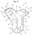
- Figure 6 shows the flat development of a shaped sheet of plate which, by means of bending, forms the structure shown at various angles in Figures 5a-5c.
- the reinforcing wings 40 extend obliquely from the edges 22 of the coupling profile section 16 and each has an end portion 80 the longitudinal axis of which is still parallel to the longitudinal axis of the edges.
- the wings have at the root of the relative end portion 80 a respective fold line 82, 84, and each portion is provided with an aperture 86 of a shape and size corresponding substantially to those of the aperture 14 provided on the appendage portion 34 of the plate.
- the longitudinal length of the portions 80 of the two wings is different and the two fold lines are not aligned, but extend in parallel directions.
- each end portion 80 is bent at a right angle onto the appendage portion 34 of the plate.
- the end portion of lesser length is bent directly onto the appendage portion 34 of the plate, and the end portion of greater length is superposed on the previous one.
- the appendage portion 34 of the plate lies in a lower plane parallel to the plane of the main portion 32 so that, following the superposition of the bent ends 80 of the reinforcing wings, the free upper surface lies in alignment with the plane of the main portion and the apertures 86 are aligned with the aperture 14 of the appendage portion of the plate.
- the anchorage of the support structure by means of plugs or similar fixing members passing through the apertures 14 of the plate makes it possible at the same time to secure the reinforcing wings to the appendage of the plate in a stable manner.
- the support structure of the invention being made of a single sheet of plate, is easy to produce while maintaining the robustness and simplicity of installation which distinguishes this component of the support systems for industrial ducting.
Landscapes
- Engineering & Computer Science (AREA)
- Architecture (AREA)
- Civil Engineering (AREA)
- Structural Engineering (AREA)
- Joining Of Building Structures In Genera (AREA)
- Installation Of Indoor Wiring (AREA)
- Connection Of Plates (AREA)
Applications Claiming Priority (2)
| Application Number | Priority Date | Filing Date | Title |
|---|---|---|---|
| ITTO20020872 ITTO20020872A1 (it) | 2002-10-09 | 2002-10-09 | Struttura di supporto per canalizzazioni industriali ancorabile a soffitto. |
| ITTO20020872 | 2002-10-09 |
Publications (3)
| Publication Number | Publication Date |
|---|---|
| EP1408593A2 true EP1408593A2 (de) | 2004-04-14 |
| EP1408593A3 EP1408593A3 (de) | 2004-12-15 |
| EP1408593B1 EP1408593B1 (de) | 2009-07-01 |
Family
ID=32012189
Family Applications (1)
| Application Number | Title | Priority Date | Filing Date |
|---|---|---|---|
| EP20030022481 Expired - Lifetime EP1408593B1 (de) | 2002-10-09 | 2003-10-08 | Trägerstruktur für eine industrielle Leitung, an einer Decke verankerbar |
Country Status (3)
| Country | Link |
|---|---|
| EP (1) | EP1408593B1 (de) |
| DE (1) | DE60328154D1 (de) |
| IT (1) | ITTO20020872A1 (de) |
Cited By (2)
| Publication number | Priority date | Publication date | Assignee | Title |
|---|---|---|---|---|
| EP2541710A1 (de) * | 2011-06-29 | 2013-01-02 | Gewiss France SA | Trägerkonsole, Herstellungsverfahren einer solchen Konsole und Kabelpritsche, die eine solche Konsole umfasst |
| WO2017164044A1 (ja) * | 2016-03-25 | 2017-09-28 | 東芝キヤリア株式会社 | 空気調和機および吊金具 |
Citations (1)
| Publication number | Priority date | Publication date | Assignee | Title |
|---|---|---|---|---|
| EP0813280A1 (de) | 1996-06-15 | 1997-12-17 | Rieth & Co. GmbH | Als Blechformteil hergestellter Ausleger |
Family Cites Families (1)
| Publication number | Priority date | Publication date | Assignee | Title |
|---|---|---|---|---|
| DE19623957C1 (de) * | 1996-03-12 | 1998-04-09 | Rieth & Co | Als Blechformteil hergestellte Kopfplatte |
-
2002
- 2002-10-09 IT ITTO20020872 patent/ITTO20020872A1/it unknown
-
2003
- 2003-10-08 EP EP20030022481 patent/EP1408593B1/de not_active Expired - Lifetime
- 2003-10-08 DE DE60328154T patent/DE60328154D1/de not_active Expired - Fee Related
Patent Citations (1)
| Publication number | Priority date | Publication date | Assignee | Title |
|---|---|---|---|---|
| EP0813280A1 (de) | 1996-06-15 | 1997-12-17 | Rieth & Co. GmbH | Als Blechformteil hergestellter Ausleger |
Cited By (3)
| Publication number | Priority date | Publication date | Assignee | Title |
|---|---|---|---|---|
| EP2541710A1 (de) * | 2011-06-29 | 2013-01-02 | Gewiss France SA | Trägerkonsole, Herstellungsverfahren einer solchen Konsole und Kabelpritsche, die eine solche Konsole umfasst |
| FR2977394A1 (fr) * | 2011-06-29 | 2013-01-04 | Gewiss France Sas | Console de supportage, procede de fabrication d'une telle console et chemin de cables comprenant une telle console |
| WO2017164044A1 (ja) * | 2016-03-25 | 2017-09-28 | 東芝キヤリア株式会社 | 空気調和機および吊金具 |
Also Published As
| Publication number | Publication date |
|---|---|
| EP1408593B1 (de) | 2009-07-01 |
| EP1408593A3 (de) | 2004-12-15 |
| DE60328154D1 (de) | 2009-08-13 |
| ITTO20020872A1 (it) | 2004-04-10 |
Similar Documents
| Publication | Publication Date | Title |
|---|---|---|
| US9109361B2 (en) | Bracing bridging member | |
| US6578335B2 (en) | Metal wall framework and clip | |
| CA2884327C (en) | Connector and system for supporting veneer panels | |
| CA2769437C (en) | Structural support device with web brace | |
| US5640823A (en) | Vertical movement clip for attaching a building member to a beam having a channel therein | |
| US5836133A (en) | Vertical movement clip for attaching a building member to a beam having a channel therein | |
| TWI796652B (zh) | 承載連接器及支持裝置 | |
| EP2990560B1 (de) | Verspannungs- und überbrückungselements | |
| EP1031669B1 (de) | Gebäuderahmen mit Sigma-Profilen | |
| CN112408150B (zh) | 导轨支架组件 | |
| EP1408593B1 (de) | Trägerstruktur für eine industrielle Leitung, an einer Decke verankerbar | |
| WO2002053846A1 (en) | Web connector | |
| EP2182128A1 (de) | Aufhängbares Deckeninselsystem | |
| GB2467039A (en) | Cladding support bracket having S-shaped profile | |
| JP2012188287A (ja) | エレベータのかご枠 | |
| JP7553605B2 (ja) | 乾式構造コネクタ、乾式構造配置、乾式構造天井を構築するためのキット及び方法 | |
| KR101413269B1 (ko) | 경량 형강 및 이를 이용한 조립시스템 | |
| US11591796B2 (en) | Truss formed of folded sheet metal | |
| JP7178898B2 (ja) | 建築物の架構 | |
| JP5752440B2 (ja) | 連結金具及びこれを備えた耐力壁並びにこれを用いた建築物 | |
| JP4480911B2 (ja) | 金属製根太 | |
| JPH0587113U (ja) | 住宅等における角形部材の固定金具 | |
| NZ704454B2 (en) | Bracing bridging member | |
| JPH066546U (ja) | 吊天井 | |
| JPH0868170A (ja) | 縦葺き屋根板用固定具 |
Legal Events
| Date | Code | Title | Description |
|---|---|---|---|
| PUAI | Public reference made under article 153(3) epc to a published international application that has entered the european phase |
Free format text: ORIGINAL CODE: 0009012 |
|
| AK | Designated contracting states |
Kind code of ref document: A2 Designated state(s): AT BE BG CH CY CZ DE DK EE ES FI FR GB GR HU IE IT LI LU MC NL PT RO SE SI SK TR |
|
| AX | Request for extension of the european patent |
Extension state: AL LT LV MK |
|
| PUAL | Search report despatched |
Free format text: ORIGINAL CODE: 0009013 |
|
| AK | Designated contracting states |
Kind code of ref document: A3 Designated state(s): AT BE BG CH CY CZ DE DK EE ES FI FR GB GR HU IE IT LI LU MC NL PT RO SE SI SK TR |
|
| AX | Request for extension of the european patent |
Extension state: AL LT LV MK |
|
| RIC1 | Information provided on ipc code assigned before grant |
Ipc: 7H 02G 3/26 B Ipc: 7H 02G 3/32 A |
|
| 17P | Request for examination filed |
Effective date: 20050530 |
|
| AKX | Designation fees paid |
Designated state(s): DE ES FR GB IT |
|
| 17Q | First examination report despatched |
Effective date: 20080428 |
|
| GRAP | Despatch of communication of intention to grant a patent |
Free format text: ORIGINAL CODE: EPIDOSNIGR1 |
|
| RIC1 | Information provided on ipc code assigned before grant |
Ipc: H02G 3/30 20060101AFI20090115BHEP |
|
| RAP1 | Party data changed (applicant data changed or rights of an application transferred) |
Owner name: BTICINO S.P.A. |
|
| GRAS | Grant fee paid |
Free format text: ORIGINAL CODE: EPIDOSNIGR3 |
|
| GRAA | (expected) grant |
Free format text: ORIGINAL CODE: 0009210 |
|
| AK | Designated contracting states |
Kind code of ref document: B1 Designated state(s): DE ES FR GB IT |
|
| REG | Reference to a national code |
Ref country code: GB Ref legal event code: FG4D |
|
| REF | Corresponds to: |
Ref document number: 60328154 Country of ref document: DE Date of ref document: 20090813 Kind code of ref document: P |
|
| PG25 | Lapsed in a contracting state [announced via postgrant information from national office to epo] |
Ref country code: ES Free format text: LAPSE BECAUSE OF FAILURE TO SUBMIT A TRANSLATION OF THE DESCRIPTION OR TO PAY THE FEE WITHIN THE PRESCRIBED TIME-LIMIT Effective date: 20091012 |
|
| PLBE | No opposition filed within time limit |
Free format text: ORIGINAL CODE: 0009261 |
|
| STAA | Information on the status of an ep patent application or granted ep patent |
Free format text: STATUS: NO OPPOSITION FILED WITHIN TIME LIMIT |
|
| 26N | No opposition filed |
Effective date: 20100406 |
|
| PG25 | Lapsed in a contracting state [announced via postgrant information from national office to epo] |
Ref country code: DE Free format text: LAPSE BECAUSE OF NON-PAYMENT OF DUE FEES Effective date: 20100501 |
|
| REG | Reference to a national code |
Ref country code: FR Ref legal event code: PLFP Year of fee payment: 14 |
|
| PGFP | Annual fee paid to national office [announced via postgrant information from national office to epo] |
Ref country code: GB Payment date: 20160928 Year of fee payment: 14 |
|
| PGFP | Annual fee paid to national office [announced via postgrant information from national office to epo] |
Ref country code: FR Payment date: 20160921 Year of fee payment: 14 |
|
| GBPC | Gb: european patent ceased through non-payment of renewal fee |
Effective date: 20171008 |
|
| REG | Reference to a national code |
Ref country code: FR Ref legal event code: ST Effective date: 20180629 |
|
| PG25 | Lapsed in a contracting state [announced via postgrant information from national office to epo] |
Ref country code: GB Free format text: LAPSE BECAUSE OF NON-PAYMENT OF DUE FEES Effective date: 20171008 |
|
| PG25 | Lapsed in a contracting state [announced via postgrant information from national office to epo] |
Ref country code: FR Free format text: LAPSE BECAUSE OF NON-PAYMENT OF DUE FEES Effective date: 20171031 |
|
| PGFP | Annual fee paid to national office [announced via postgrant information from national office to epo] |
Ref country code: IT Payment date: 20220920 Year of fee payment: 20 |