EP1408457B1 - Vehicular remote locking/unlocking system - Google Patents
Vehicular remote locking/unlocking system Download PDFInfo
- Publication number
- EP1408457B1 EP1408457B1 EP20030022884 EP03022884A EP1408457B1 EP 1408457 B1 EP1408457 B1 EP 1408457B1 EP 20030022884 EP20030022884 EP 20030022884 EP 03022884 A EP03022884 A EP 03022884A EP 1408457 B1 EP1408457 B1 EP 1408457B1
- Authority
- EP
- European Patent Office
- Prior art keywords
- signal
- transmission
- vehicle
- identification information
- unlocking
- Prior art date
- Legal status (The legal status is an assumption and is not a legal conclusion. Google has not performed a legal analysis and makes no representation as to the accuracy of the status listed.)
- Expired - Lifetime
Links
- 230000005540 biological transmission Effects 0.000 claims description 77
- 230000000977 initiatory effect Effects 0.000 claims description 2
- 230000008054 signal transmission Effects 0.000 description 55
- 238000000034 method Methods 0.000 description 15
- 230000002457 bidirectional effect Effects 0.000 description 3
- 238000010586 diagram Methods 0.000 description 3
- 238000012790 confirmation Methods 0.000 description 2
- 230000002708 enhancing effect Effects 0.000 description 2
- 230000007257 malfunction Effects 0.000 description 2
- 238000013475 authorization Methods 0.000 description 1
Images


Classifications
-
- G—PHYSICS
- G07—CHECKING-DEVICES
- G07C—TIME OR ATTENDANCE REGISTERS; REGISTERING OR INDICATING THE WORKING OF MACHINES; GENERATING RANDOM NUMBERS; VOTING OR LOTTERY APPARATUS; ARRANGEMENTS, SYSTEMS OR APPARATUS FOR CHECKING NOT PROVIDED FOR ELSEWHERE
- G07C9/00—Individual registration on entry or exit
- G07C9/00174—Electronically operated locks; Circuits therefor; Nonmechanical keys therefor, e.g. passive or active electrical keys or other data carriers without mechanical keys
- G07C9/00309—Electronically operated locks; Circuits therefor; Nonmechanical keys therefor, e.g. passive or active electrical keys or other data carriers without mechanical keys operated with bidirectional data transmission between data carrier and locks
- G07C2009/00341—Electronically operated locks; Circuits therefor; Nonmechanical keys therefor, e.g. passive or active electrical keys or other data carriers without mechanical keys operated with bidirectional data transmission between data carrier and locks keyless data carrier having more than one limited data transmission ranges
- G07C2009/00357—Electronically operated locks; Circuits therefor; Nonmechanical keys therefor, e.g. passive or active electrical keys or other data carriers without mechanical keys operated with bidirectional data transmission between data carrier and locks keyless data carrier having more than one limited data transmission ranges and the lock having more than one limited data transmission ranges
-
- G—PHYSICS
- G07—CHECKING-DEVICES
- G07C—TIME OR ATTENDANCE REGISTERS; REGISTERING OR INDICATING THE WORKING OF MACHINES; GENERATING RANDOM NUMBERS; VOTING OR LOTTERY APPARATUS; ARRANGEMENTS, SYSTEMS OR APPARATUS FOR CHECKING NOT PROVIDED FOR ELSEWHERE
- G07C2209/00—Indexing scheme relating to groups G07C9/00 - G07C9/38
- G07C2209/60—Indexing scheme relating to groups G07C9/00174 - G07C9/00944
- G07C2209/63—Comprising locating means for detecting the position of the data carrier, i.e. within the vehicle or within a certain distance from the vehicle
Definitions
- the present invention relates to a vehicular remote locking/unlocking system according to the preamble of claim 1 wherein a vehicle user equipped with a portable device operates trigger means located in a vehicle and a locking/unlocking means carries out locking/unlocking of an opening member of the vehicle.
- Technique 1 includes external antennas 2 and 3 directed toward spaces outside a vehicle and having signal transmission ranges indicated as I and II, respectively, and an internal antenna 5 directed toward a space within the vehicle and having a signal transmission range indicated as III.
- Technique 1 locks and unlocks doors only if a transponder 6 is present outside a passenger compartment, by sequentially transmitting interrogation code signals from the internal antenna 5 and the external antennas 2 and 3 when a start switch (a door outer handle, or a door inner handle) is operated, and sequentially evaluating a received response signal from the transponder 6 to detect the position of the transponder 6.
- a start switch a door outer handle, or a door inner handle
- Technique 2 prevents unauthorized unlocking of the doors if the transponder 6 is left behind in the passenger compartment, by sequentially transmitting interrogation code signals with antenna identification codes added thereto and making the transponder 6 only transmit a response signal in response to the interrogation code signals transmitted from the external antennas 2 and 3.
- the response signal has to be transmitted even when the transponder 6 is present within the passenger compartment, the number of communications in Technique 1 increases, thereby wasting the power of the transponder 6.
- the signal transmission range of the internal antenna 5 is reduced due to interference, such as, for example, noise, if the transponder 6 is left behind in a place, such as a door pocket, which is typically positioned on the outermost side within the passenger compartment (a range where I and II overlap), since no response signal is transmitted in response to the interrogation code signal from the internal antenna 5, it is determined that the transponder 6 is present outside the passenger compartment, and a malfunction occurs.
- the signal transmission range referred to here means a range in which the transponder 6 is able to receive the interrogation code signal.
- Document FR 2 814 188 A1 discloses a vehicular remote locking/unlocking system according to the preamble of claim 1, wherein each internal antenna transmits only one disable signal before a request -to-send signal is transmitted.
- the present invention has been achieved in view of the above-mentioned circumstances, and provides a vehicular remote locking/unlocking system according to claim 1 wherein, when a portable device is left behind within a passenger compartment, unauthorized locking/unlocking of an opening member of the vehicle is reliably prevented.
- a first aspect of the present invention provides a vehicular remote locking/unlocking system including first transmission means which is located in a vehicle and which transmits to a predetermined area outside the vehicle a request signal requesting transmission of identification information.
- Second transmission means located in the vehicle transmits a transmission disable signal to a predetermined area within the vehicle, the transmission disabling signal disabling transmission of identification information for a predetermined period of time.
- a portable device carried by a vehicle user transmits identification information upon receiving the request signal.
- Receiving means located in the vehicle receives the identification information from the portable device.
- Trigger means located in the vehicle outputs a trigger signal initiating operation of the first and second transmission means, the trigger means being operated by the vehicle user.
- Locking/unlocking means carries out the locking/unlocking of an opening member of the vehicle when the identification information received by the receiving means matches identification information stored on the vehicle side.
- the trigger means outputs the trigger signal
- the second transmission means transmits the transmission disable signal a plurality of times in succession so as to disable transmission of the identification information from the portable device for a predetermined period of time, thereby disabling the operation of the locking/unlocking means when the portable device is present within the vehicle.
- the portable device if the portable device is left behind within a passenger compartment when the trigger means is operated to operate the locking/unlocking means of the vehicle, because the portable device receives the transmission disable signal transmitted by the second transmission means and transmission of the identification information from the portable device is thus disabled, the operation of the locking/unlocking means can reliably be disabled, thereby preventing unauthorized locking/unlocking of the opening member of the vehicle.
- the portable device if the vehicle user is equipped with the portable device when the trigger means is operated to operate the locking/unlocking means of the vehicle, the portable device does not receive the transmission disable signal transmitted by the second transmission means, but the portable device receives the request signal transmitted by the first transmission means, and transmits the identification information.
- the locking/unlocking means it is possible to operate the locking/unlocking means to lock/unlock the opening member of the vehicle.
- the portable device receives the transmission disable signal, transmission of the identification information from the portable device is disabled for the predetermined period of time. Therefore, even when the portable device is left behind in a position where the signal transmission range of the first transmission means overlaps the signal transmission range of the second transmission means, it is possible to disable transmission of the identification information from the portable device, thereby preventing unauthorized locking/unlocking of the opening member of the vehicle.
- the second transmission means transmits the transmission disable signal a plurality of times in succession, even if any one of the transmission disable signals transmitted a plurality of times in succession is inhibited by noise, the remainder of the transmission disable signals can reliably disable transmission of the identification information from the portable device within the passenger compartment, thereby enhancing the reliability of the vehicular remote locking/unlocking device. Furthermore, since the portable device transmits identification information only when located outside the passenger compartment and transmits no identification information when located within the passenger compartment, the power consumption of the portable device is substantially reduced, i.e., minimized.
- a vehicular remote locking/unlocking system wherein when the receiving means receives from the portable device the identification information that matches the identification information stored on the vehicle side, after the second transmission means re-transmits the transmission disable signal, the first transmission means transmits a secondary request signal containing the identification information.
- the portable device When the portable device is not in a state in which transmission is disabled and the identification information contained in the secondary request signal received by the portable device is its own identification information, the portable device re-transmits the identification information.
- the locking/unlocking means carries out locking/unlocking of the opening member of the vehicle.
- a portable transceiver 11 of an embodiment corresponds to the portable device of the present invention
- locking switches 22L and 22R and unlocking switches 23L and 23R of the embodiment correspond to the trigger means of the present invention
- a door lock actuator 27 of the embodiment corresponds to the locking/unlocking means of the present invention
- first LF antennas 28L and 28R of the embodiment correspond to the first transmission means of the present invention
- second LF antennas 29f and 29r of the embodiment correspond to the second transmission means of the present invention
- an RF receiver 26 and an RF antenna 30 of the embodiment correspond to the receiving means of the present invention
- an ID signal and a function signal f(x) of the embodiment correspond to the identification information of the present invention.
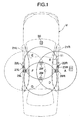
- FIG. 1 is a schematic diagram showing the overall arrangement of a vehicular remote locking/unlocking system, according to an embodiment of the present invention
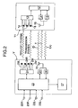
- FIG. 2 is a block diagram of the vehicular remote locking/unlocking system illustrated in FIG. 1;
- FIG. 3 is a time chart explaining operation of the vehicular remote locking/unlocking system of FIG. 1 when a vehicle user is equipped with a portable transceiver;
- FIG. 4 is a time chart explaining the operation of the vehicular remote locking/unlocking system of FIG. 1 when a portable transceiver is present within a passenger compartment;
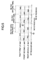
- FIG. 5 is a time chart, corresponding to the time chart of FIG. 3, when an ID signal from the portable transceiver is not received again;
- FIG. 6 is a time chart explaining operation of the vehicular remote locking/unlocking system of FIG. 1 when a portable transceiver is present in illustrated Areas A through G;
- FIG. 7 is a flow chart explaining the operation of the vehicular remote locking/unlocking system of FIG. 1 on a vehicle side of the vehicular remote locking/unlocking system;
- FIG. 8 is a flow chart explaining the operation of the vehicular remote locking/unlocking system of FIG. 1 on a portable device side of the vehicular remote locking/unlocking system.
- Figure 9 is a diagram similar to Figure 1 showing the prior art.
- a vehicular remote locking/unlocking system which locks and unlocks doors of a vehicle V without using a key, includes a card-type portable transceiver 11 for a vehicle user to carry, such as, for example, in a pocket or a bag.
- a control unit 12 of the portable transceiver 11 Connected to a control unit 12 of the portable transceiver 11 are an LF (low frequency) receiver 13, an RF (radio frequency) transmitter 14, and an RF (radio frequency) receiver 15.
- LF receiver 13 low frequency
- RF (radio frequency) transmitter 14 Connected to the LF receiver 13 are three LF antennas 16, 17, and 18 having axes orthogonal to each other.
- a common RF antenna 19 is connected to the RF transmitter 14 and the RF receiver 15.
- a locking switch 22L and an unlocking switch 23L provided on a left front door 21 L
- a locking switch 22R and an unlocking switch 23R provided on a right front door 21 R
- an LF transmitter 24, an RF transmitter 25, an RF receiver 26, and a door lock actuator 27 are connected to the LF transmitter 24.
- a common RF antenna 30 is connected to the RF transmitter 25 and the RF receiver 26.
- First LF antenna 28L which transmits an ID signal request-to-send signal, is provided to the rear of the left front door 21 L and has a signal transmission range (shown as a circle having the left-hand first LF antenna 28L at its center).
- the signal transmission range of the first antenna 28L covers the position of a vehicle user standing near the left front door 21 L to operate the locking switch 22L or the unlocking switch 23L.
- the first LF antenna 28R which transmits an ID signal request-to-send signal, is provided to the rear of the right front door 21 R and has a signal transmission range, (shown as a circle having the right-hand first LF antenna 28R at its center).
- the signal transmission range of the first LF antenna 28R covers the position of a vehicle user standing near the right front door 21 R to operate the locking switch 22R or the unlocking switch 23R.
- Second LF antennas 29f and 29r which transmit an ID signal transmission disable signal, are disposed on the center line of the vehicle body and are separated from each other in the longitudinal direction.
- the signal transmission ranges of the second LF antennas 29f and 29r (shown as two circles having the second LF antennas 29f and 29r at their centers), substantially cover the whole area of the passenger compartment.
- the RF antenna 30 is provided at an appropriate position of the vehicle V.
- the signal transmission range referred to herein is a range where the portable transceiver 11 receives a signal from the first and second LF antennas 28L, 28R, 29f and 29r.
- the signal transmission range of the first LF antenna 28R and the signal transmission ranges of the second LF antennas 29f and 29r define Areas A to G.
- Area A only an ID signal request-to-send signal from the first LF antenna 28R can be received by the portable transceiver 11.
- Area B an ID signal request-to-send signal from the first LF antenna 28R and an ID signal transmission disable signal from the front second LF antenna 29f can be received by the portable transceiver 11.
- an ID signal request-to-send signal from the first LF antenna 28R and ID signal transmission disable signals from the second LF antennas 29f and 29r can be received by the portable transceiver 11.
- an ID signal request-to-send signal from the first LF antenna 28R and an ID signal transmission disable signal from the rearward located second LF antenna 29r can be received by the portable transceiver 11.
- an ID signal transmission disable signal from the forward located second LF antenna 29f can be received by the portable transceiver 11.
- ID signal transmission disable signals from the second LF antennas 29f and 29r can be received by the portable transceiver 11.
- an ID signal transmission disable signal from the rearward located second LF antenna 29r can be received by the portable transceiver 11.
- an ID signal request-to-send signal is transmitted from the corresponding first LF antenna 28L or 28R on the vehicle V side.
- the portable transceiver 11 receives the ID signal request-to-send signal via the LF antennas 16 to 18 and then transmits an ID signal, which is stored in the control unit 12, from the RF antenna 19.
- the control unit 20 receives the ID signal via the RF antenna 30 on the vehicle V side and then confirms whether the ID signal is a legitimate ID signal pre-stored in the control unit 20. If the ID signal is a legitimate ID signal, the control unit 20 then transmits a random number signal x from the RF antenna 30.
- the portable transceiver 11 receives the random number signal x via the RF antenna 19 and then transmits from the RF antenna 19 a function signal f(x) calculated using the random number signal x according to a program stored in the control unit 12.
- the control unit 20 receives the function signal f(x) via the RF antenna 30 on the vehicle V side and then compares the received function signal f(x) with a function signal f(x) calculated therein from the random number signal x . If both function signals f(x) match, the control unit 20 instructs the door lock actuator 27 to operate and unlock the front doors 21 L and 21 R.
- the above-mentioned operation occurs when a vehicle user equipped with the legitimate portable transceiver 11 uses either the locking switch 22L or 22R or the unlocking switch 23L or 23R.
- a person other than the vehicle user can lock and unlock the doors 21L and 21 R simply by operating either the locking switch 22L or 22R or the unlocking switch 23L or 23R to instruct the door lock actuator 27 to operate, thereby facilitating unauthorized use or entry of the vehicle V.
- the second LF antennas 29f and 29r disposed within the passenger compartment transmit ID signal transmission disable signals, which, for a predetermined period of time, disable transmission of an ID signal from the portable transceiver 11 left behind within the vehicle and operation of the door lock actuator 27.
- a trigger signal is output when the vehicle user operates the unlocking switch 23R of the right door 21 R. Based on the output trigger signal, an ID signal transmission disable signal is first transmitted from the forward located second LF antenna 29f. An ID signal transmission disable signal is subsequently transmitted from the rearward located second LF antenna 29r. An ID signal request-to-send signal is subsequently transmitted from the first LF antenna 28R on the right side (on the operated unlocking switch 23R side).
- the portable transceiver 11 if the portable transceiver 11 is located in Area A, for example, the vehicle user is in possession of the portable transceiver 11, since the ID signal transmission disable signals are not received by the portable transceiver 11, the portable transceiver 11 transmits an ID signal in response to the received ID signal request-to-send signal. In contrast, if the portable transceiver 11 is located in Areas B through G, for example, when the vehicle user has left the portable transceiver 11 behind somewhere within the passenger compartment, the portable transceiver 11 does not transmit the ID signal.
- the portable transceiver 11 if the portable transceiver 11 is located in Areas B, C, or D, even though the portable transceiver 11 is able to receive the ID signal request-to-send signal, the ID signal transmission disable signal has already been received. Therefore, the ID signal will not be transmitted unless a predetermined period of time elapses after the ID signal transmission disable signal is received. If the portable transceiver 11 is located in Areas E, F, or G, the ID signal request-to-send signal is not received, so that the ID signal will be transmitted.
- the reception time chart of the RF antenna 30 shown in FIG. 3 illustrates the situation where the portable transceiver 11 is located in Area A.
- the reception time chart (1) of the RF antenna 30 shown in FIG. 4 illustrates the situation where the portable transceiver 11 is located within any of Areas B, C, D, E, F, and G.
- T1 and T2 in FIG. 3 and FIG. 4 denote transmission disabled periods.
- the transmission disabled period T1 represents a transmission disabled period when, among two ID signal transmission disable signals a and b of the forward located second LF antenna 29f, the signal a is received by the portable transceiver 11, which is located in an area other than Area A.
- the transmission disabled period T2 represents a transmission disabled period when, among two ID signal transmission disable signals a and b of the rearward located second LF antenna 29r, the signal b is received by the portable transceiver 11, which is located in an area other than Area A.
- the ID signal transmission disable signal is not received, as shown in the reception time chart of the RF antenna 30 of FIG. 3, so that the RF antenna 30 receives the ID signal transmitted from the portable transceiver 11 in response to reception of the ID signal request-to-send signal transmitted from the right first LF antenna 28R.
- the portable transceiver 11 When the portable transceiver 11 is located in an area other than Area A, that is, any one of Areas B, C, D, E, F, and G, the portable transceiver 11 receives an ID signal transmission disable signal transmitted from either one of the second LF antenna 29f or 29r, so that the portable transceiver 11 is set in a transmission disabled state, at shortest, until the transmission disabled period T1 has elapsed and, at longest, until the transmission disabled period T2 has elapsed. As shown in the reception time chart (1) for the RF antenna 30 of FIG.
- the portable transceiver 11 even though the portable transceiver 11 is able to receive an ID signal request-to-send signal transmitted from the right first LF antenna 29R, the portable transceiver 11 does not transmit an ID signal, and therefore the RF antenna 30 (and the RF receiver 26) cannot receive an ID signal.
- the above-mentioned ID signal transmission disable signals a and b are substantially the same signals and only differ in terms of the order of transmission. Also, the transmission disabled periods T1 and T2 are the same periods of time.
- t1 in FIG. 3 denotes an LF signal reception disabled period of the LF receiver 13 of the portable transceiver 11 and will be described below along with the explanation of FIG. 8.
- the portable transceiver 11 does not transmit an ID signal even though a cycle of transmitting ID signal transmission disable signals and an ID signal request-to-send signal is completed by the forward located second LF antenna 29f, the rearward located second LF antenna 29r, and the first LF antenna 28R, the cycle is retried twice.
- an ID signal cannot be transmitted the first time, even though the portable transceiver 11 is located outside the vehicle V.
- an ID signal can be transmitted the second time (i.e., a transmission re-try) when the influence of the noise is gone or dissipates. That is, the locking/unlocking procedure can reliably be carried out by one switching operation.
- the signal transmission ranges become small. Therefore, if the portable transceiver 11 is left behind on the outer periphery of the signal transmission ranges of the ID signal transmission disable signals, for example, in a pocket of the door 21 L or 21 R, there is the possibility that the portable transceiver 11 may not receive an ID signal transmission disable signal and erroneously transmit an ID signal.
- the portable transceiver 11 when the portable transceiver 11 receives an ID signal transmission disable signal, transmission of an ID signal from the portable transceiver 11 is disabled for a predetermined period of time until transmission of a subsequent ID signal transmission disable signal is completed. Therefore, the portable transceiver 11 is prevented from erroneously transmitting an ID signal and the doors 21 L and 21 R from being locked/unlocked without authorization even when the portable transceiver 11 is left behind in the door pocket. Further, since each ID signal transmission disable signal is formed from two successive signals a and b (see FIG.
- the portable transceiver 11 transmits an ID signal only when located outside the passenger compartment and does not transmit an ID signal when located within the passenger compartment, the power consumption of the portable transceiver 11 is substantially reduced, i.e., minimized.
- an ID signal transmission disable signal is transmitted from the forward located second LF antenna 29f, an ID signal transmission disable signal is subsequently transmitted from the rearward located second LF antenna 29r, and an ID signal request-to-send signal is subsequently transmitted from the first LF antenna 28R.
- the ID signal request-to-send signal accompanies the ID signal received from the portable transceiver 11.
- the ID signal request-to-send signal accompanying the ID signal is received by the portable transceiver 11, if the ID signal matches ID information pre-stored in the portable transceiver 11, then the portable transceiver 11 transmits an ID signal.
- the portable transceiver 11 If the ID signal received by the RF antenna 30 on the vehicle V side matches ID information pre-stored on the vehicle V side, the portable transceiver 11 is authenticated and verified as being legitimate, and, as described above, a random number signal x is transmitted from the RF antenna 30 on the vehicle V side.
- the position of the portable transceiver 11 is confirmed using the ID signal request-to-send signal which specifies the portable transceiver 11 having the ID signal received during the first position confirmation process. Therefore, it is possible to more reliably confirm that the vehicle user is equipped with the portable transceiver 11.
- Step S1 the vehicle user presses the locking switch 22L or 22R or the unlocking switch 23L or 23R and a trigger signal is output.
- Step S2 two ID signal transmission disable signals, denoted by a and b in FIG. 3, are transmitted from the forward located second LF antenna 29f.
- Step S3 two ID signal transmission disable signals are similarly transmitted from the rearward located second LF antenna 29r.
- Step S4 an ID signal request-to-send signal is output from either one of the first LF antennas 28L and 28R.
- Step S5 If in Step S5 an ID signal is received and the ID signal is authenticated in Step S6 (i.e., if the received ID signal matches an ID signal stored in the control unit 20 on the vehicle V side), then bidirectional authentication is carried out between the vehicle V and the portable transceiver 11 in Step S7 using a random number signal x and a function signal f(x) at a radio frequency. If in Step S8 authentication is obtained (i.e., if the received function signal f(x) matches a function signal f(x) derived from the random number x in the control unit 20 on the vehicle V side), then in Step S9 the door lock actuator 27 is operated so as to lock or unlock the doors 21 L and 21 R (see FIG. 2).
- Step S5 If an ID signal is not received in Step S5, the ID signal is not authenticated in Step S6, or authentication is not obtained from the random number signal x and the function signal f(x) in Step S8, then Steps S2 to S8 are retried twice in Step S10.
- Step S21 If in Step S21 an ID signal transmission disable signals is not received from the second LF antennas 29f and 29r, and an ID signal request-to-send signal is received from the first LF antenna 28L or 28R in Step S22, then in Step S23 an ID signal is transmitted from the RF antenna 19 on the portable transceiver 11 side, and bidirectional authentication is carried out in Step S24.
- Step S21 an ID signal transmission disable signal is received from the second LF antenna 29f or 29r, then in Step S25 transmission of an ID signal from the portable device 11 is disabled for a predetermined period of time.
- the LF receiver 13 of the portable transceiver 11 when the LF receiver 13 of the portable transceiver 11 receives a first ID signal transmission disable signal, the LF receiver 13 is put in a reception disabled state for a predetermined period of time, thus making reception of an ID signal request-to-send signal impossible and thereby disabling transmission of an ID signal.
- the transmission disabled state in an embodiment of the present invention is explained in detail by reference to FIG. 3 and FIG. 6.
- the LF receiver 13 of the portable transceiver 11 receives an ID signal transmission disable signal transmitted from the second LF antenna 29f or 29r in Step S21, the sequence stays in Step S25 until the LF signal reception disabled period t1 shown in FIG. 3 or FIG. 6 has elapsed. Accordingly, the LF receiver 13 cannot receive any ID signal request-to-send signals transmitted from the first LF antennas 28L and 28R or any ID signal transmission disable signals transmitted from the second LF antennas 29f and 29r during the period t1.
- the portable transceiver 11 when the LF receiver 13 of the portable transceiver 11 receives the ID signal transmission disable signal a transmitted from the forward located second LF antenna 29f in FIG. 3, it cannot receive an ID signal request-to-send signal transmitted from the right first LF antenna 28R. Therefore, the portable transceiver 11 does not transmits an ID signal, and the transmission disabled period due to reception of the ID signal transmission disable signal a becomes T1.
- the LF signal reception disabled period is set to be slightly longer than the period from the time when transmission of the ID signal transmission disable signal first transmitted by operating the locking switch 22L or 22R or the unlocking switch 23L or 23R is completed to the time when transmission of the ID signal request-to-send signal is completed.
- the number of first LF antennas 28L and 28R is two and the number of second LF antennas 29f and 29r is two, however, it is within the scope of the present invention to appropriately change the number antenna.
- four first LF antennas may be located at four corners of the vehicle V and three second LF antennas may be located at front, center, and
- an ID signal transmission disable signal is transmitted twice in succession, however it is within the scope of the present invention to transmit the signal three or more times in succession.
- the opening member of the present invention is not limited to the doors 21 L and 21 R of the vehicle V, but may also be or include a trunk lid.
- a second transmission device transmits identification information transmission disable signal, before a first transmission device transmits identification information request signal.
- a portable device of the vehicular remote system receives the transmission disable signal, even if the portable device receives a subsequent request signal, transmission of identification information from the portable device is disabled for a predetermined period of time, thereby disabling operation of a door lock actuator. Since the second transmission device transmits a transmission disable signal a plurality of times in succession, the influence of noise is eliminated, thereby reliably preventing the portable transceiver within the vehicle from outputting an ID signal.
Landscapes
- Engineering & Computer Science (AREA)
- Computer Networks & Wireless Communication (AREA)
- Physics & Mathematics (AREA)
- General Physics & Mathematics (AREA)
- Lock And Its Accessories (AREA)
Description
- The present invention relates to a vehicular remote locking/unlocking system according to the preamble of
claim 1 wherein a vehicle user equipped with a portable device operates trigger means located in a vehicle and a locking/unlocking means carries out locking/unlocking of an opening member of the vehicle. - European Patent No. 0523602 B1 discloses, as shown in FIG. 9, two techniques (i.e.,
Technique 1 and Technique 2).Technique 1 includesexternal antennas internal antenna 5 directed toward a space within the vehicle and having a signal transmission range indicated as III.Technique 1 locks and unlocks doors only if atransponder 6 is present outside a passenger compartment, by sequentially transmitting interrogation code signals from theinternal antenna 5 and theexternal antennas transponder 6 to detect the position of thetransponder 6.Technique 2 prevents unauthorized unlocking of the doors if thetransponder 6 is left behind in the passenger compartment, by sequentially transmitting interrogation code signals with antenna identification codes added thereto and making thetransponder 6 only transmit a response signal in response to the interrogation code signals transmitted from theexternal antennas - However, because the response signal has to be transmitted even when the
transponder 6 is present within the passenger compartment, the number of communications inTechnique 1 increases, thereby wasting the power of thetransponder 6. There is also the problem that, when the signal transmission range of theinternal antenna 5 is reduced due to interference, such as, for example, noise, if thetransponder 6 is left behind in a place, such as a door pocket, which is typically positioned on the outermost side within the passenger compartment (a range where I and II overlap), since no response signal is transmitted in response to the interrogation code signal from theinternal antenna 5, it is determined that thetransponder 6 is present outside the passenger compartment, and a malfunction occurs. - In the case of
Technique 2, when thetransponder 6 is left behind in the range of III that does not overlap with I, that is, in a middle part of the passenger compartment, unauthorized locking/unlocking can be prevented. However, when thetransponder 6 is left behind in a place, such as a door pocket, although the interrogation code signal from theinternal antenna 5 is not acknowledged, because a response signal is transmitted to the interrogation code signal that is subsequently transmitted from theexternal antennas - It should be noted that the signal transmission range referred to here means a range in which the
transponder 6 is able to receive the interrogation code signal. -
Document FR 2 814 188 A1 discloses a vehicular remote locking/unlocking system according to the preamble ofclaim 1, wherein each internal antenna transmits only one disable signal before a request -to-send signal is transmitted. - The present invention has been achieved in view of the above-mentioned circumstances, and provides a vehicular remote locking/unlocking system according to
claim 1 wherein, when a portable device is left behind within a passenger compartment, unauthorized locking/unlocking of an opening member of the vehicle is reliably prevented. - In order to provide such a system, a first aspect of the present invention provides a vehicular remote locking/unlocking system including first transmission means which is located in a vehicle and which transmits to a predetermined area outside the vehicle a request signal requesting transmission of identification information. Second transmission means located in the vehicle transmits a transmission disable signal to a predetermined area within the vehicle, the transmission disabling signal disabling transmission of identification information for a predetermined period of time. A portable device carried by a vehicle user transmits identification information upon receiving the request signal. Receiving means located in the vehicle receives the identification information from the portable device. Trigger means located in the vehicle outputs a trigger signal initiating operation of the first and second transmission means, the trigger means being operated by the vehicle user. Locking/unlocking means carries out the locking/unlocking of an opening member of the vehicle when the identification information received by the receiving means matches identification information stored on the vehicle side. When the trigger means outputs the trigger signal, before the first transmission means transmits the request signal, the second transmission means transmits the transmission disable signal a plurality of times in succession so as to disable transmission of the identification information from the portable device for a predetermined period of time, thereby disabling the operation of the locking/unlocking means when the portable device is present within the vehicle.
- In accordance with this arrangement, if the portable device is left behind within a passenger compartment when the trigger means is operated to operate the locking/unlocking means of the vehicle, because the portable device receives the transmission disable signal transmitted by the second transmission means and transmission of the identification information from the portable device is thus disabled, the operation of the locking/unlocking means can reliably be disabled, thereby preventing unauthorized locking/unlocking of the opening member of the vehicle. On the other hand, if the vehicle user is equipped with the portable device when the trigger means is operated to operate the locking/unlocking means of the vehicle, the portable device does not receive the transmission disable signal transmitted by the second transmission means, but the portable device receives the request signal transmitted by the first transmission means, and transmits the identification information. Therefore, it is possible to operate the locking/unlocking means to lock/unlock the opening member of the vehicle. In particular, when the portable device receives the transmission disable signal, transmission of the identification information from the portable device is disabled for the predetermined period of time. Therefore, even when the portable device is left behind in a position where the signal transmission range of the first transmission means overlaps the signal transmission range of the second transmission means, it is possible to disable transmission of the identification information from the portable device, thereby preventing unauthorized locking/unlocking of the opening member of the vehicle. Moreover, since the second transmission means transmits the transmission disable signal a plurality of times in succession, even if any one of the transmission disable signals transmitted a plurality of times in succession is inhibited by noise, the remainder of the transmission disable signals can reliably disable transmission of the identification information from the portable device within the passenger compartment, thereby enhancing the reliability of the vehicular remote locking/unlocking device. Furthermore, since the portable device transmits identification information only when located outside the passenger compartment and transmits no identification information when located within the passenger compartment, the power consumption of the portable device is substantially reduced, i.e., minimized.
- Furthermore, according to the invention, there is provided a vehicular remote locking/unlocking system wherein when the receiving means receives from the portable device the identification information that matches the identification information stored on the vehicle side, after the second transmission means re-transmits the transmission disable signal, the first transmission means transmits a secondary request signal containing the identification information. When the portable device is not in a state in which transmission is disabled and the identification information contained in the secondary request signal received by the portable device is its own identification information, the portable device re-transmits the identification information. When the identification information received by the receiving means successively matches the identification information stored on the vehicle side, the locking/unlocking means carries out locking/unlocking of the opening member of the vehicle. In accordance with this arrangement, since the process of 'transmitting the request signal from the first transmission means' and 'receiving legitimate identification information from the portable device' is repeated twice and, in particular, in the second process the position of the portable device is confirmed by the request signal specifying the portable device having the identification information received in the first process, it is further reliably possible to confirm that the vehicle user is equipped with the portable device, thereby reliably preventing malfunction of the vehicular remote locking/unlocking device.
- A
portable transceiver 11 of an embodiment corresponds to the portable device of the present invention, lockingswitches switches door lock actuator 27 of the embodiment corresponds to the locking/unlocking means of the present invention,first LF antennas second LF antennas RF receiver 26 and anRF antenna 30 of the embodiment correspond to the receiving means of the present invention, and an ID signal and a function signal f(x) of the embodiment correspond to the identification information of the present invention. - The above-mentioned characteristics and advantages of the present invention will become apparent from an explanation of an embodiment described in detail below by reference to the attached drawings.
- FIG. 1 is a schematic diagram showing the overall arrangement of a vehicular remote locking/unlocking system, according to an embodiment of the present invention;
- FIG. 2 is a block diagram of the vehicular remote locking/unlocking system illustrated in FIG. 1;
- FIG. 3 is a time chart explaining operation of the vehicular remote locking/unlocking system of FIG. 1 when a vehicle user is equipped with a portable transceiver;
- FIG. 4 is a time chart explaining the operation of the vehicular remote locking/unlocking system of FIG. 1 when a portable transceiver is present within a passenger compartment;
- FIG. 5 is a time chart, corresponding to the time chart of FIG. 3, when an ID signal from the portable transceiver is not received again;
- FIG. 6 is a time chart explaining operation of the vehicular remote locking/unlocking system of FIG. 1 when a portable transceiver is present in illustrated Areas A through G;
- FIG. 7 is a flow chart explaining the operation of the vehicular remote locking/unlocking system of FIG. 1 on a vehicle side of the vehicular remote locking/unlocking system; and
- FIG. 8 is a flow chart explaining the operation of the vehicular remote locking/unlocking system of FIG. 1 on a portable device side of the vehicular remote locking/unlocking system.
Figure 9 is a diagram similar to Figure 1 showing the prior art. - As shown in FIG. 1 and FIG. 2, a vehicular remote locking/unlocking system according to an embodiment of the present invention, which locks and unlocks doors of a vehicle V without using a key, includes a card-type
portable transceiver 11 for a vehicle user to carry, such as, for example, in a pocket or a bag. Connected to acontrol unit 12 of theportable transceiver 11 are an LF (low frequency)receiver 13, an RF (radio frequency)transmitter 14, and an RF (radio frequency)receiver 15. Connected to theLF receiver 13 are threeLF antennas common RF antenna 19 is connected to theRF transmitter 14 and theRF receiver 15. - Connected to a control unit 20 provided on the vehicle V of the vehicle side remote system are a locking
switch 22L and an unlockingswitch 23L provided on a leftfront door 21 L, a lockingswitch 22R and an unlockingswitch 23R provided on a rightfront door 21 R, anLF transmitter 24, anRF transmitter 25, anRF receiver 26, and adoor lock actuator 27. Left and rightfirst LF antennas second LF antennas LF transmitter 24. Acommon RF antenna 30 is connected to theRF transmitter 25 and theRF receiver 26. -
First LF antenna 28L, which transmits an ID signal request-to-send signal, is provided to the rear of the leftfront door 21 L and has a signal transmission range (shown as a circle having the left-handfirst LF antenna 28L at its center). The signal transmission range of thefirst antenna 28L covers the position of a vehicle user standing near the leftfront door 21 L to operate the lockingswitch 22L or the unlockingswitch 23L. In a similar manner, thefirst LF antenna 28R, which transmits an ID signal request-to-send signal, is provided to the rear of the rightfront door 21 R and has a signal transmission range, (shown as a circle having the right-handfirst LF antenna 28R at its center). The signal transmission range of thefirst LF antenna 28R covers the position of a vehicle user standing near the rightfront door 21 R to operate the lockingswitch 22R or the unlockingswitch 23R. -
Second LF antennas second LF antennas second LF antennas RF antenna 30 is provided at an appropriate position of the vehicle V. - The signal transmission range referred to herein is a range where the
portable transceiver 11 receives a signal from the first andsecond LF antennas - The signal transmission range of the
first LF antenna 28R and the signal transmission ranges of thesecond LF antennas first LF antenna 28R can be received by theportable transceiver 11. In Area B, an ID signal request-to-send signal from thefirst LF antenna 28R and an ID signal transmission disable signal from the frontsecond LF antenna 29f can be received by theportable transceiver 11. In Area C, an ID signal request-to-send signal from thefirst LF antenna 28R and ID signal transmission disable signals from thesecond LF antennas portable transceiver 11. In Area D, an ID signal request-to-send signal from thefirst LF antenna 28R and an ID signal transmission disable signal from the rearward locatedsecond LF antenna 29r can be received by theportable transceiver 11. In Area E, only an ID signal transmission disable signal from the forward locatedsecond LF antenna 29f can be received by theportable transceiver 11. In Area F, ID signal transmission disable signals from thesecond LF antennas portable transceiver 11. In Area G, only an ID signal transmission disable signal from the rearward locatedsecond LF antenna 29r can be received by theportable transceiver 11. - The basic operation of an embodiment of the vehicular remote system will now be explained.
- When a vehicle user equipped with a legitimate
portable transceiver 11 presses either the unlockingswitch 23L of theleft door 21 L or the unlockingswitch 23R of theright door 21 R, an ID signal request-to-send signal is transmitted from the correspondingfirst LF antenna portable transceiver 11 receives the ID signal request-to-send signal via theLF antennas 16 to 18 and then transmits an ID signal, which is stored in thecontrol unit 12, from theRF antenna 19. The control unit 20 receives the ID signal via theRF antenna 30 on the vehicle V side and then confirms whether the ID signal is a legitimate ID signal pre-stored in the control unit 20. If the ID signal is a legitimate ID signal, the control unit 20 then transmits a random number signal x from theRF antenna 30. - The
portable transceiver 11 receives the random number signal x via theRF antenna 19 and then transmits from the RF antenna 19 a function signal f(x) calculated using the random number signal x according to a program stored in thecontrol unit 12. The control unit 20 receives the function signal f(x) via theRF antenna 30 on the vehicle V side and then compares the received function signal f(x) with a function signal f(x) calculated therein from the random number signal x. If both function signals f(x) match, the control unit 20 instructs the door lock actuator 27 to operate and unlock thefront doors - In a similar manner, when a vehicle user equipped with a legitimate
portable transceiver 11 presses the lockingswitch 22L of theleft door 21 L or the lockingswitch 22R of theright door 21 R, the control unit 20 instructs the door lock actuator 27 to operate and to lock thefront doors - The above-mentioned operation occurs when a vehicle user equipped with the legitimate
portable transceiver 11 uses either the lockingswitch switch portable transceiver 11 is left behind within the passenger compartment, a person other than the vehicle user can lock and unlock thedoors switch switch second LF antennas portable transceiver 11 left behind within the vehicle and operation of thedoor lock actuator 27. - As shown in FIG. 3 and FIG. 6, for example, a trigger signal is output when the vehicle user operates the unlocking
switch 23R of the right door 21 R. Based on the output trigger signal, an ID signal transmission disable signal is first transmitted from the forward locatedsecond LF antenna 29f. An ID signal transmission disable signal is subsequently transmitted from the rearward locatedsecond LF antenna 29r. An ID signal request-to-send signal is subsequently transmitted from thefirst LF antenna 28R on the right side (on the operated unlockingswitch 23R side). - During the above-described process, if the
portable transceiver 11 is located in Area A, for example, the vehicle user is in possession of theportable transceiver 11, since the ID signal transmission disable signals are not received by theportable transceiver 11, theportable transceiver 11 transmits an ID signal in response to the received ID signal request-to-send signal. In contrast, if theportable transceiver 11 is located in Areas B through G, for example, when the vehicle user has left theportable transceiver 11 behind somewhere within the passenger compartment, theportable transceiver 11 does not transmit the ID signal. In other words, if theportable transceiver 11 is located in Areas B, C, or D, even though theportable transceiver 11 is able to receive the ID signal request-to-send signal, the ID signal transmission disable signal has already been received. Therefore, the ID signal will not be transmitted unless a predetermined period of time elapses after the ID signal transmission disable signal is received. If theportable transceiver 11 is located in Areas E, F, or G, the ID signal request-to-send signal is not received, so that the ID signal will be transmitted. - The reception time chart of the
RF antenna 30 shown in FIG. 3 illustrates the situation where theportable transceiver 11 is located in Area A. The reception time chart (1) of theRF antenna 30 shown in FIG. 4 illustrates the situation where theportable transceiver 11 is located within any of Areas B, C, D, E, F, and G. T1 and T2 in FIG. 3 and FIG. 4 denote transmission disabled periods. The transmission disabled period T1 represents a transmission disabled period when, among two ID signal transmission disable signals a and b of the forward locatedsecond LF antenna 29f, the signal a is received by theportable transceiver 11, which is located in an area other than Area A. The transmission disabled period T2 represents a transmission disabled period when, among two ID signal transmission disable signals a and b of the rearward locatedsecond LF antenna 29r, the signal b is received by theportable transceiver 11, which is located in an area other than Area A. - That is, when the
portable transceiver 11 is present in Area A, the ID signal transmission disable signal is not received, as shown in the reception time chart of theRF antenna 30 of FIG. 3, so that theRF antenna 30 receives the ID signal transmitted from theportable transceiver 11 in response to reception of the ID signal request-to-send signal transmitted from the rightfirst LF antenna 28R. - When the
portable transceiver 11 is located in an area other than Area A, that is, any one of Areas B, C, D, E, F, and G, theportable transceiver 11 receives an ID signal transmission disable signal transmitted from either one of thesecond LF antenna portable transceiver 11 is set in a transmission disabled state, at shortest, until the transmission disabled period T1 has elapsed and, at longest, until the transmission disabled period T2 has elapsed. As shown in the reception time chart (1) for theRF antenna 30 of FIG. 4, even though theportable transceiver 11 is able to receive an ID signal request-to-send signal transmitted from the right first LF antenna 29R, theportable transceiver 11 does not transmit an ID signal, and therefore the RF antenna 30 (and the RF receiver 26) cannot receive an ID signal. - The above-mentioned ID signal transmission disable signals a and b are substantially the same signals and only differ in terms of the order of transmission. Also, the transmission disabled periods T1 and T2 are the same periods of time. t1 in FIG. 3 denotes an LF signal reception disabled period of the
LF receiver 13 of theportable transceiver 11 and will be described below along with the explanation of FIG. 8. - As illustrated by FIG. 4, if the
portable transceiver 11 does not transmit an ID signal even though a cycle of transmitting ID signal transmission disable signals and an ID signal request-to-send signal is completed by the forward locatedsecond LF antenna 29f, the rearward locatedsecond LF antenna 29r, and thefirst LF antenna 28R, the cycle is retried twice. - As shown in the reception time chart (2) for the
RF antenna 30 of FIG. 4, when the signal transmission ranges of thesecond LF antennas portable transceiver 11 is located outside the vehicle V. However, an ID signal can be transmitted the second time (i.e., a transmission re-try) when the influence of the noise is gone or dissipates. That is, the locking/unlocking procedure can reliably be carried out by one switching operation. - On the other hand, when noise is superimposed on the ID signal transmission disable signals transmitted by the
second LF antennas portable transceiver 11 is left behind on the outer periphery of the signal transmission ranges of the ID signal transmission disable signals, for example, in a pocket of thedoor portable transceiver 11 may not receive an ID signal transmission disable signal and erroneously transmit an ID signal. - However, in an embodiment of the present invention, when the
portable transceiver 11 receives an ID signal transmission disable signal, transmission of an ID signal from theportable transceiver 11 is disabled for a predetermined period of time until transmission of a subsequent ID signal transmission disable signal is completed. Therefore, theportable transceiver 11 is prevented from erroneously transmitting an ID signal and thedoors portable transceiver 11 is left behind in the door pocket. Further, since each ID signal transmission disable signal is formed from two successive signals a and b (see FIG. 3), even if one of the two signals a and b is subjected to interference, such as, for example, from noise, the other signal is received by theportable transceiver 11, thereby enhancing the operation reliability of the vehicular remote locking/unlocking system. Moreover, since theportable transceiver 11 transmits an ID signal only when located outside the passenger compartment and does not transmit an ID signal when located within the passenger compartment, the power consumption of theportable transceiver 11 is substantially reduced, i.e., minimized. - As described above, even when it is confirmed that a vehicle user equipped with a legitimate
portable transceiver 11 has operated the unlockingswitch 23R, to make sure, it is re-determined whether theportable transceiver 11 is located within the passenger compartment, as will be described below. - As shown in FIG. 3, when the
RF antenna 30 on the vehicle V side receives an ID signal transmitted by theportable transceiver 11, an ID signal transmission disable signal is transmitted from the forward locatedsecond LF antenna 29f, an ID signal transmission disable signal is subsequently transmitted from the rearward locatedsecond LF antenna 29r, and an ID signal request-to-send signal is subsequently transmitted from thefirst LF antenna 28R. The ID signal request-to-send signal accompanies the ID signal received from theportable transceiver 11. When the ID signal request-to-send signal accompanying the ID signal is received by theportable transceiver 11, if the ID signal matches ID information pre-stored in theportable transceiver 11, then theportable transceiver 11 transmits an ID signal. If the ID signal received by theRF antenna 30 on the vehicle V side matches ID information pre-stored on the vehicle V side, theportable transceiver 11 is authenticated and verified as being legitimate, and, as described above, a random number signal x is transmitted from theRF antenna 30 on the vehicle V side. - During the second position confirmation process of the
portable transceiver 11, the position of theportable transceiver 11 is confirmed using the ID signal request-to-send signal which specifies theportable transceiver 11 having the ID signal received during the first position confirmation process. Therefore, it is possible to more reliably confirm that the vehicle user is equipped with theportable transceiver 11. - As shown in FIG. 5, if the ID signal request-to-send signal accompanying the ID signal is not received by the
portable transceiver 11, or if it is received but the ID information does not match, the re-try explained in FIG. 4 is repeated twice. - Although a case in which the vehicle user has operated the unlocking
switch 23R of theright door 21 R is explained above, a similar operation is carried out in a case in which the lockingswitch 22R of theright door 21 R is operated or in a case in which the lockingswitch 22L or the unlockingswitch 23L of theleft door 21 L is operated. - In the time charts of FIG. 3 and FIG. 5 primarily, when an ID signal is received via the
RF antenna 30, transmission from the forward locatedsecond RF antenna 29f actually starts after a bidirectional authentication period. - The operation of the vehicle V side of the vehicular remote locking/unlocking system is now explained by reference to FIG. 7.
- In Step S1, the vehicle user presses the locking
switch switch second LF antenna 29f. Next, in Step S3, two ID signal transmission disable signals are similarly transmitted from the rearward locatedsecond LF antenna 29r. Subsequently, in Step S4, an ID signal request-to-send signal is output from either one of thefirst LF antennas - If in Step S5 an ID signal is received and the ID signal is authenticated in Step S6 (i.e., if the received ID signal matches an ID signal stored in the control unit 20 on the vehicle V side), then bidirectional authentication is carried out between the vehicle V and the
portable transceiver 11 in Step S7 using a random number signal x and a function signal f(x) at a radio frequency. If in Step S8 authentication is obtained (i.e., if the received function signal f(x) matches a function signal f(x) derived from the random number x in the control unit 20 on the vehicle V side), then in Step S9 thedoor lock actuator 27 is operated so as to lock or unlock thedoors - If an ID signal is not received in Step S5, the ID signal is not authenticated in Step S6, or authentication is not obtained from the random number signal x and the function signal f(x) in Step S8, then Steps S2 to S8 are retried twice in Step S10.
- The operation of the
portable transceiver 11 side of the vehicular remote locking/unlocking system is now explained by reference to the flow chart of FIG. 8. - If in Step S21 an ID signal transmission disable signals is not received from the
second LF antennas first LF antenna RF antenna 19 on theportable transceiver 11 side, and bidirectional authentication is carried out in Step S24. On the other hand, if in Step S21 an ID signal transmission disable signal is received from thesecond LF antenna portable device 11 is disabled for a predetermined period of time. - In the present embodiment, when the
LF receiver 13 of theportable transceiver 11 receives a first ID signal transmission disable signal, theLF receiver 13 is put in a reception disabled state for a predetermined period of time, thus making reception of an ID signal request-to-send signal impossible and thereby disabling transmission of an ID signal. - The transmission disabled state in an embodiment of the present invention is explained in detail by reference to FIG. 3 and FIG. 6. When the
LF receiver 13 of theportable transceiver 11 receives an ID signal transmission disable signal transmitted from thesecond LF antenna LF receiver 13 cannot receive any ID signal request-to-send signals transmitted from thefirst LF antennas second LF antennas - That is, when the
LF receiver 13 of theportable transceiver 11 receives the ID signal transmission disable signal a transmitted from the forward locatedsecond LF antenna 29f in FIG. 3, it cannot receive an ID signal request-to-send signal transmitted from the rightfirst LF antenna 28R. Therefore, theportable transceiver 11 does not transmits an ID signal, and the transmission disabled period due to reception of the ID signal transmission disable signal a becomes T1. - As shown in FIG. 3 and FIG. 6, the LF signal reception disabled period is set to be slightly longer than the period from the time when transmission of the ID signal transmission disable signal first transmitted by operating the locking
switch switch - For example, in the exemplary embodiment of the present invention described above, the number of
first LF antennas second LF antennas - rear positions along the center line of the vehicle V.
- Furthermore, in the exemplary embodiment of the present invention described above, an ID signal transmission disable signal is transmitted twice in succession, however it is within the scope of the present invention to transmit the signal three or more times in succession.
- Moreover, the opening member of the present invention is not limited to the
doors
In a vehicular remote locking/unlocking system, when a locking or unlocking switch outputs a trigger signal, a second transmission device transmits identification information transmission disable signal, before a first transmission device transmits identification information request signal. When a portable device of the vehicular remote system receives the transmission disable signal, even if the portable device receives a subsequent request signal, transmission of identification information from the portable device is disabled for a predetermined period of time, thereby disabling operation of a door lock actuator. Since the second transmission device transmits a transmission disable signal a plurality of times in succession, the influence of noise is eliminated, thereby reliably preventing the portable transceiver within the vehicle from outputting an ID signal.
Claims (1)
- A vehicular remote locking/unlocking system comprising:first transmission means (28L, 28R) provided in a vehicle (V), for transmitting a request signal to a predetermined area outside the vehicle (V), the request signal requesting transmission of identification information;second transmission means (29f, 29r) provided in the vehicle (V) for transmitting a transmission disable signal to a predetermined area within the vehicle (V), the transmission disable signal disabling transmission of identification information for a predetermined period of time (T2);a portable device (11) which transmits identification information upon receiving the request signal;receiving means (26, 30) provided in the vehicle (V), for receiving the identification information from the portable device (11);trigger means (22L, 22R, 23L, 23R) provided in the vehicle, for outputting a trigger signal initiating operation of the first and second transmission means (28L, 28R, 29f, 29r) when the trigger means (22L, 22R, 23L, 23R) is operated by a vehicle user; andlocking/unlocking means (27) for carrying out locking/unlocking of an opening member of the vehicle (V) when the identification information received by the receiving means (26, 30) matches identification information stored on the vehicle side,wherein when the trigger means (22L, 22R, 23L, 23R) outputs the trigger signal before the first transmission means (28L, 28R) transmits the request signal, the second transmission means (29f, 29r) transmits the transmission disable signal a plurality of times in succession and disables transmission of the identification information from the portable device (11) for a predetermined period of time (T2), and operation of the locking/unlocking means (27) is disabled when the portable device (11) is located within the vehicle (V),characterized in thatwhen the receiving means (26, 30) receives the identification information matching the identification information stored on the vehicle side from the portable device (11), after the second transmission means (29f, 29r) re-transmits the transmission disable signal, the first transmission means (28L, 28R) transmits a secondary request signal containing the identification information; wherein when the portable device (11) is not in a state in which transmission is disabled and the identification information contained in the secondary request signal received by the portable device (11) is its own identification information, the portable device re-transmits the identification information; and wherein when the identification information received by the receiving means (26, 30) successively matches the identification information stored on the vehicle side, the locking/unlocking means (27) carries out locking/unlocking of the opening member of the vehicle (V).
Applications Claiming Priority (2)
| Application Number | Priority Date | Filing Date | Title |
|---|---|---|---|
| JP2002295362A JP3894870B2 (en) | 2002-10-08 | 2002-10-08 | Remote locking and unlocking device for vehicles |
| JP2002295362 | 2002-10-08 |
Publications (3)
| Publication Number | Publication Date |
|---|---|
| EP1408457A2 EP1408457A2 (en) | 2004-04-14 |
| EP1408457A3 EP1408457A3 (en) | 2005-01-05 |
| EP1408457B1 true EP1408457B1 (en) | 2006-12-13 |
Family
ID=32025518
Family Applications (1)
| Application Number | Title | Priority Date | Filing Date |
|---|---|---|---|
| EP20030022884 Expired - Lifetime EP1408457B1 (en) | 2002-10-08 | 2003-10-08 | Vehicular remote locking/unlocking system |
Country Status (4)
| Country | Link |
|---|---|
| US (1) | US6980082B2 (en) |
| EP (1) | EP1408457B1 (en) |
| JP (1) | JP3894870B2 (en) |
| DE (1) | DE60310332T8 (en) |
Families Citing this family (18)
| Publication number | Priority date | Publication date | Assignee | Title |
|---|---|---|---|---|
| US7318616B1 (en) * | 2003-01-31 | 2008-01-15 | Owen Bradley | Vehicle filing cabinet |
| JP2006233533A (en) * | 2005-02-24 | 2006-09-07 | Matsushita Electric Ind Co Ltd | Remote controller for vehicle |
| CN101138237A (en) * | 2005-03-08 | 2008-03-05 | 皇家飞利浦电子股份有限公司 | Multiple user control of a down loadable application |
| JP4529762B2 (en) * | 2005-03-30 | 2010-08-25 | 株式会社デンソー | Vehicle door control system |
| JP4485984B2 (en) * | 2005-04-01 | 2010-06-23 | 株式会社東海理化電機製作所 | Communication control device |
| JP2007107249A (en) * | 2005-10-13 | 2007-04-26 | Calsonic Kansei Corp | Mobile device for vehicle keyless apparatus |
| JP5095144B2 (en) | 2006-07-06 | 2012-12-12 | カルソニックカンセイ株式会社 | Keyless device for vehicle |
| JP2008050892A (en) * | 2006-08-28 | 2008-03-06 | Alps Electric Co Ltd | Keyless entry device |
| FR2913278B1 (en) * | 2007-03-01 | 2009-04-17 | Siemens Vdo Automotive Sas | METHOD FOR THE PROVISIONAL INHIBITION, IN ITS DETECTION IN A LOCKED VEHICLE, OF A PORTABLE REMOTE CONTROL BOX, IDENTIFIED, OF A HANDS-FREE ACCESS DEVICE |
| US20110140839A1 (en) * | 2009-12-11 | 2011-06-16 | Honda Motor Co., Ltd. | Method and system for disabling passive entry key located inside a vehicle |
| JP5218572B2 (en) * | 2011-01-07 | 2013-06-26 | 株式会社デンソー | In-vehicle device control system |
| JP5604314B2 (en) * | 2011-01-13 | 2014-10-08 | オムロンオートモーティブエレクトロニクス株式会社 | Detection device, detection system, and detection method for radio wave handset |
| DE102014101086A1 (en) * | 2014-01-29 | 2015-07-30 | Huf Hülsbeck & Fürst Gmbh & Co. Kg | Mobile device for a keyless entry or actuation system for motor vehicles |
| DE102017214038A1 (en) * | 2017-08-11 | 2019-02-14 | Continental Automotive Gmbh | Anti-theft device for a vehicle |
| KR102191785B1 (en) * | 2019-02-25 | 2020-12-16 | (주)디지파츠 | Smartkey signal control device of carsharing vehicle and system thereof |
| US10855394B1 (en) * | 2019-08-06 | 2020-12-01 | Firstech, LLC | Interfering radio and vehicle key locker |
| US11861439B2 (en) * | 2019-10-15 | 2024-01-02 | Sony Group Corporation | Antenna device, control method, and program |
| JP2022075136A (en) * | 2020-11-06 | 2022-05-18 | 株式会社アイシン | Door handle device |
Citations (1)
| Publication number | Priority date | Publication date | Assignee | Title |
|---|---|---|---|---|
| US20010029415A1 (en) * | 1996-08-22 | 2001-10-11 | Flick Kenneth E. | Remote vehicle function control system using data bus adaptor cartridge and associated methods |
Family Cites Families (9)
| Publication number | Priority date | Publication date | Assignee | Title |
|---|---|---|---|---|
| JP2546842B2 (en) * | 1987-06-16 | 1996-10-23 | 日産自動車株式会社 | Vehicle locking / unlocking control device |
| DE4123654A1 (en) | 1991-07-17 | 1993-01-21 | Bayerische Motoren Werke Ag | METHOD FOR DETECTING A PORTABLE TRANSPONDER INCLUDED IN THE VEHICLE |
| FR2697864B1 (en) * | 1992-11-06 | 1995-01-06 | Valeo Electronique | System for remotely controlling the locking and unlocking of the doors and openings of a passenger compartment, in particular of a motor vehicle. |
| DE19735658C1 (en) * | 1997-08-16 | 1998-07-30 | Bosch Gmbh Robert | Vehicle locking system using transponders inside |
| DE19836957C1 (en) * | 1998-08-14 | 1999-09-30 | Siemens Ag | Theft protection arrangement for motor vehicle |
| FR2791728B1 (en) | 1999-04-02 | 2001-06-08 | Valeo Securite Habitacle | DEVICE FOR SECURING AN ACCESS SYSTEM PROVIDED WITH AN IDENTIFICATION MEANS AND AN IDENTIFIER, FOR A MOTOR VEHICLE |
| US6765471B1 (en) * | 1999-04-02 | 2004-07-20 | Valeo Securite Habitacle | Device for improving the security of an access system equipped with an identification means and an identifier, for a motor vehicle |
| JP3426547B2 (en) * | 1999-10-04 | 2003-07-14 | 本田技研工業株式会社 | Vehicle remote door lock control device |
| DE10045762C2 (en) | 2000-09-15 | 2002-08-29 | Siemens Ag | Anti-theft system for a motor vehicle |
-
2002
- 2002-10-08 JP JP2002295362A patent/JP3894870B2/en not_active Expired - Fee Related
-
2003
- 2003-10-08 EP EP20030022884 patent/EP1408457B1/en not_active Expired - Lifetime
- 2003-10-08 DE DE2003610332 patent/DE60310332T8/en active Active
- 2003-10-08 US US10/680,405 patent/US6980082B2/en not_active Expired - Lifetime
Patent Citations (1)
| Publication number | Priority date | Publication date | Assignee | Title |
|---|---|---|---|---|
| US20010029415A1 (en) * | 1996-08-22 | 2001-10-11 | Flick Kenneth E. | Remote vehicle function control system using data bus adaptor cartridge and associated methods |
Also Published As
| Publication number | Publication date |
|---|---|
| DE60310332D1 (en) | 2007-01-25 |
| US6980082B2 (en) | 2005-12-27 |
| JP3894870B2 (en) | 2007-03-22 |
| US20040130462A1 (en) | 2004-07-08 |
| DE60310332T2 (en) | 2007-03-29 |
| JP2004131974A (en) | 2004-04-30 |
| DE60310332T8 (en) | 2007-07-12 |
| EP1408457A3 (en) | 2005-01-05 |
| EP1408457A2 (en) | 2004-04-14 |
Similar Documents
| Publication | Publication Date | Title |
|---|---|---|
| EP1408457B1 (en) | Vehicular remote locking/unlocking system | |
| EP1408458B1 (en) | Vehicular remote control system | |
| EP1695880B1 (en) | Vehicle remote-operation apparatus | |
| US6437683B1 (en) | Keyless security entry control method for motor vehicles | |
| US7388466B2 (en) | Integrated passive entry and remote keyless entry system | |
| JP6292719B2 (en) | Vehicle wireless communication system, vehicle control device, portable device | |
| US8310338B2 (en) | Smart keyless entry system | |
| US6944528B2 (en) | Wireless communication system for vehicle | |
| US9126564B2 (en) | Communication apparatus for vehicle | |
| US20040142732A1 (en) | Radio type locking/unlocking device | |
| US20050033484A1 (en) | Locking system for a motor vehicle | |
| US20170021801A1 (en) | On-vehicle apparatus control system, on-vehicle control device, and portable machine | |
| JPH08246728A (en) | Keyless entry device | |
| JP2008196228A (en) | Smart keyless device of vehicle | |
| JP3679194B2 (en) | Wireless door unlock system for vehicles | |
| WO2019138819A1 (en) | Communication system | |
| US7932627B2 (en) | Electric steering lock, in particular for a motor vehicle | |
| EP0905337B1 (en) | Starting switch for a vehicle and the system thereof | |
| US6838976B2 (en) | Keyless access control device and method for motor vehicles | |
| US6850154B2 (en) | Method and device for protecting motor vehicles against theft | |
| JP4230419B2 (en) | Remote locking / unlocking control device for vehicle | |
| JPH11245770A (en) | Vehicular remote control system, vehicle side device and portable unit | |
| US6580354B1 (en) | Control system and method for controlling motor vehicle functions | |
| JP2007031962A (en) | Unlocking device for vehicle | |
| JP3783905B2 (en) | Remote control transmission / reception device and vehicle wireless door lock control device |
Legal Events
| Date | Code | Title | Description |
|---|---|---|---|
| PUAI | Public reference made under article 153(3) epc to a published international application that has entered the european phase |
Free format text: ORIGINAL CODE: 0009012 |
|
| AK | Designated contracting states |
Kind code of ref document: A2 Designated state(s): AT BE BG CH CY CZ DE DK EE ES FI FR GB GR HU IE IT LI LU MC NL PT RO SE SI SK TR |
|
| AX | Request for extension of the european patent |
Extension state: AL LT LV MK |
|
| PUAL | Search report despatched |
Free format text: ORIGINAL CODE: 0009013 |
|
| AK | Designated contracting states |
Kind code of ref document: A3 Designated state(s): AT BE BG CH CY CZ DE DK EE ES FI FR GB GR HU IE IT LI LU MC NL PT RO SE SI SK TR |
|
| AX | Request for extension of the european patent |
Extension state: AL LT LV MK |
|
| 17P | Request for examination filed |
Effective date: 20050519 |
|
| AKX | Designation fees paid |
Designated state(s): DE GB |
|
| GRAP | Despatch of communication of intention to grant a patent |
Free format text: ORIGINAL CODE: EPIDOSNIGR1 |
|
| RIN1 | Information on inventor provided before grant (corrected) |
Inventor name: KAMIKURA, AKIRAC/O HONDA GIJUTSU KENKYUSHO K K Inventor name: ARIE, SHINICHIC/O HONDA GIJUTSU KENKYUSHO K K Inventor name: ASAKURA, SUGURUC/O HONDA GIJUTSU KENKYUSHO K K Inventor name: YOSHIMURA, KENTAROC/O HONDA GIJUTSU KENKYUSHO K K Inventor name: SAWADA, KENICHIC/O HONDA GIJUTSU KENKYUSHO K K Inventor name: HAYASHI, NAOKI Inventor name: SUEOKA, KAZUHIKO Inventor name: UEDA, SHINICHIC/O HONDA GIJUTSU KENKYUSHO K K |
|
| GRAS | Grant fee paid |
Free format text: ORIGINAL CODE: EPIDOSNIGR3 |
|
| GRAA | (expected) grant |
Free format text: ORIGINAL CODE: 0009210 |
|
| RIN1 | Information on inventor provided before grant (corrected) |
Inventor name: YOSHIMURA, KENTAROC/O HONDA GIJUTSU KENKYUSHO Inventor name: ARIE, SHINICHIC/O HONDA GIJUTSU KENKYUSHO Inventor name: SUEOKA, KAZUHIKOC/O HONDA GIJUTSU KENKYUSHO Inventor name: HAYASHI, NAOKIC/O HONDA GIJUTSU KENKYUSHO Inventor name: SAWADA, KENICHIC/O HONDA GIJUTSU KENKYUSHO Inventor name: ASAKURA, SUGURUC/O HONDA GIJUTSU KENKYUSHO Inventor name: KAMIKURA, AKIRAC/O HONDA GIJUTSU KENKYUSHO Inventor name: UEDA, SHINICHIC/O HONDA GIJUTSU KENKYUSHO |
|
| AK | Designated contracting states |
Kind code of ref document: B1 Designated state(s): DE GB |
|
| RAP1 | Party data changed (applicant data changed or rights of an application transferred) |
Owner name: HONDA MOTOR CO., LTD. Owner name: MATSUSHITA ELECTRIC INDUSTRIAL CO., LTD. |
|
| REG | Reference to a national code |
Ref country code: GB Ref legal event code: FG4D |
|
| REF | Corresponds to: |
Ref document number: 60310332 Country of ref document: DE Date of ref document: 20070125 Kind code of ref document: P |
|
| RIN2 | Information on inventor provided after grant (corrected) |
Inventor name: HAYASHI, NAOKI Inventor name: ARIE, SHINICHIC/O HONDA GIJUTSU KENKYUSHO Inventor name: KAMIKURA, AKIRAC/O HONDA GIJUTSU KENKYUSHO Inventor name: SUEOKA, KAZUHIKO Inventor name: UEDA, SHINICHIC/O HONDA GIJUTSU KENKYUSHO Inventor name: ASAKURA, SUGURUC/O HONDA GIJUTSU KENKYUSHO Inventor name: YOSHIMURA, KENTAROC/O HONDA GIJUTSU KENKYUSHO Inventor name: SAWADA, KENICHIC/O HONDA GIJUTSU KENKYUSHO |
|
| PLBE | No opposition filed within time limit |
Free format text: ORIGINAL CODE: 0009261 |
|
| STAA | Information on the status of an ep patent application or granted ep patent |
Free format text: STATUS: NO OPPOSITION FILED WITHIN TIME LIMIT |
|
| 26N | No opposition filed |
Effective date: 20070914 |
|
| PGFP | Annual fee paid to national office [announced via postgrant information from national office to epo] |
Ref country code: GB Payment date: 20131002 Year of fee payment: 11 |
|
| GBPC | Gb: european patent ceased through non-payment of renewal fee |
Effective date: 20141008 |
|
| PG25 | Lapsed in a contracting state [announced via postgrant information from national office to epo] |
Ref country code: GB Free format text: LAPSE BECAUSE OF NON-PAYMENT OF DUE FEES Effective date: 20141008 |
|
| PGFP | Annual fee paid to national office [announced via postgrant information from national office to epo] |
Ref country code: DE Payment date: 20171004 Year of fee payment: 15 |
|
| REG | Reference to a national code |
Ref country code: DE Ref legal event code: R119 Ref document number: 60310332 Country of ref document: DE |
|
| PG25 | Lapsed in a contracting state [announced via postgrant information from national office to epo] |
Ref country code: DE Free format text: LAPSE BECAUSE OF NON-PAYMENT OF DUE FEES Effective date: 20190501 |