US7932627B2 - Electric steering lock, in particular for a motor vehicle - Google Patents
Electric steering lock, in particular for a motor vehicle Download PDFInfo
- Publication number
- US7932627B2 US7932627B2 US12/252,426 US25242608A US7932627B2 US 7932627 B2 US7932627 B2 US 7932627B2 US 25242608 A US25242608 A US 25242608A US 7932627 B2 US7932627 B2 US 7932627B2
- Authority
- US
- United States
- Prior art keywords
- steering lock
- electronics
- electric steering
- lock
- drive
- Prior art date
- Legal status (The legal status is an assumption and is not a legal conclusion. Google has not performed a legal analysis and makes no representation as to the accuracy of the status listed.)
- Active
Links
Images


Classifications
-
- B—PERFORMING OPERATIONS; TRANSPORTING
- B60—VEHICLES IN GENERAL
- B60R—VEHICLES, VEHICLE FITTINGS, OR VEHICLE PARTS, NOT OTHERWISE PROVIDED FOR
- B60R25/00—Fittings or systems for preventing or indicating unauthorised use or theft of vehicles
- B60R25/20—Means to switch the anti-theft system on or off
- B60R25/24—Means to switch the anti-theft system on or off using electronic identifiers containing a code not memorised by the user
-
- B—PERFORMING OPERATIONS; TRANSPORTING
- B60—VEHICLES IN GENERAL
- B60R—VEHICLES, VEHICLE FITTINGS, OR VEHICLE PARTS, NOT OTHERWISE PROVIDED FOR
- B60R25/00—Fittings or systems for preventing or indicating unauthorised use or theft of vehicles
- B60R25/01—Fittings or systems for preventing or indicating unauthorised use or theft of vehicles operating on vehicle systems or fittings, e.g. on doors, seats or windscreens
- B60R25/02—Fittings or systems for preventing or indicating unauthorised use or theft of vehicles operating on vehicle systems or fittings, e.g. on doors, seats or windscreens operating on the steering mechanism
- B60R25/021—Fittings or systems for preventing or indicating unauthorised use or theft of vehicles operating on vehicle systems or fittings, e.g. on doors, seats or windscreens operating on the steering mechanism restraining movement of the steering column or steering wheel hub, e.g. restraining means controlled by ignition switch
- B60R25/0215—Fittings or systems for preventing or indicating unauthorised use or theft of vehicles operating on vehicle systems or fittings, e.g. on doors, seats or windscreens operating on the steering mechanism restraining movement of the steering column or steering wheel hub, e.g. restraining means controlled by ignition switch using electric means, e.g. electric motors or solenoids
- B60R25/02153—Fittings or systems for preventing or indicating unauthorised use or theft of vehicles operating on vehicle systems or fittings, e.g. on doors, seats or windscreens operating on the steering mechanism restraining movement of the steering column or steering wheel hub, e.g. restraining means controlled by ignition switch using electric means, e.g. electric motors or solenoids comprising a locking member radially and linearly moved towards the steering column
-
- B—PERFORMING OPERATIONS; TRANSPORTING
- B60—VEHICLES IN GENERAL
- B60R—VEHICLES, VEHICLE FITTINGS, OR VEHICLE PARTS, NOT OTHERWISE PROVIDED FOR
- B60R25/00—Fittings or systems for preventing or indicating unauthorised use or theft of vehicles
- B60R25/20—Means to switch the anti-theft system on or off
- B60R25/2063—Ignition switch geometry
-
- Y—GENERAL TAGGING OF NEW TECHNOLOGICAL DEVELOPMENTS; GENERAL TAGGING OF CROSS-SECTIONAL TECHNOLOGIES SPANNING OVER SEVERAL SECTIONS OF THE IPC; TECHNICAL SUBJECTS COVERED BY FORMER USPC CROSS-REFERENCE ART COLLECTIONS [XRACs] AND DIGESTS
- Y10—TECHNICAL SUBJECTS COVERED BY FORMER USPC
- Y10T—TECHNICAL SUBJECTS COVERED BY FORMER US CLASSIFICATION
- Y10T70/00—Locks
- Y10T70/50—Special application
- Y10T70/5889—For automotive vehicles
- Y10T70/5956—Steering mechanism with switch
Definitions
- the invention relates to an electric steering lock.
- Steering locks are used to lock the steering column in a motor vehicle in order to increase protection against theft.
- DE 37 39 172 C1 discloses an electric steering lock for a drive authorization system in a motor vehicle.
- the steering lock has a locking element which can be moved between a first position and a second position and is intended to lock the steering shaft when the key has been removed. In the first position, the locking element can be brought into locking engagement with a latched-in position on the steering shaft in the steering wheel column and, in the second position, is not in engagement with the latched-in position.
- the steering lock has a drive for moving the locking element, which drive has an electric motor and is supplied with electrical voltage by the battery in the motor vehicle.
- the control unit is usually an ignition lock which, when operated by the associated key, controls the drive for locking and/or unlocking the steering lock.
- Such drive authorization systems have also been developed further with so-called “keyless” functionalities.
- KeylessGo an operating signal for drive authorization is automatically transmitted between a device in the form of an electronic key and the control unit if the user is inside the motor vehicle and operates a start/stop button on the dashboard, for example. If the device is authorized, the drive for moving the locking element can then be controlled into the respective position.
- An object of the invention is to configure the electric steering lock, in particular for a drive authorization system with keyless functionality, in such a manner that it is possible to dispense with an additional control unit.
- the electronics of the steering lock according to the invention can generate the signals needed for drive authorization.
- the drive authorization system therefore does not need an additional control unit to generate the signals needed for operation of the motor vehicle.
- the electronics autonomously control the drive in an intrinsically safe manner, thus enabling independent operation of the steering lock without an additional control unit. In this case, it is also ensured that the conventional safety requirements are met without monitoring by means of an additional control unit.
- a KeylessGo system which can be installed in the vehicle to be provided with keyless functionality by replacing a component or by adding components while retaining the interfaces of the basic vehicle is provided in the invention.
- the electric steering lock generates those signals which are used to trigger functions which can otherwise be achieved by an electric ignition lock which is part of a conventional drive authorization system.
- the electronics generate the key position signals which are otherwise output by electric switches, for example, in the ignition lock in the case of manual operation using the ignition key.
- the steering lock provides a type of key simulation of the electric ignition lock by generating these signals in the electric steering lock itself. These signals then both control the terminals and block lock control.
- the electronics independently control the drive according to the operating sequence without the need for the signals which are otherwise output by the ignition lock.
- electromagnetic signals can be interchanged between the device, which is with the user and is in the form of an electronic key, for example, and the motor vehicle.
- the electronics and the device have transmitters and/or receivers. If desired, the electronics may also interact with a transmitter and/or receiver in a separate control unit in the motor vehicle for this purpose.
- At least one of the transmitted signals may be a coded operating signal for authenticating the device. Following positive evaluation of the transmitted operating signal, that is to say the electronic key is authorized, the drive for moving the locking element is then controlled into the respective position by the electronics.
- the electronics and, if appropriate, the associated transmitter and/or receiver are integrated in the electric steering lock.
- Such a configuration is suitable for confined installation spaces in motor vehicles.
- An antenna for transmitting the signals is connected to the transmitter and/or receiver for the electric steering lock.
- the antenna may be provided with a suitable apparatus for controlling the low-frequency (LF) signals for waking up and/or locating the device. If desired for the purpose of reducing the installation space, the antenna may also be integrated in the electric steering lock.
- LF low-frequency
- the drive for the steering lock may have an electric motor.
- the electric motor is expediently supplied with electrical voltage by the battery in the motor vehicle.
- a start/stop pushbutton which interacts with the electronics is expediently connected to the electric steering lock.
- the start/stop pushbutton in the respective installation space of the motor vehicle in which the locking cylinder of the ignition lock is otherwise situated. Therefore, the user can advantageously operate the arrangement in an essentially conventional manner.
- the basic vehicle can be provided with the special feature of keyless functionality in a cost-effective manner.
- the drive authorization system according to the invention with an access authorization system for the motor vehicle, which is likewise provided with a type of keyless entry functionality.
- the electric steering lock expediently interacts with the access authorization system, which again contributes to saving corresponding control units.
- an electric steering lock which is intrinsically safe and simulates the position of the key using the switch signals of the basic vehicle is provided.
- This electric steering lock is implemented in the installation space of the mechanical lock of the basic vehicle, which is otherwise present.
- the interfaces for steering are identical to those for mechanical locking.
- the electric steering lock may also be replaced with a mechanical lock with a rotary catch by virtue of the rotary catch electronics maintaining the interfaces of the electric steering lock.
- the inductive antennas are controlled by an additional control unit or a so-called “intelligent” antenna.
- the keyless sequences are implemented in the electric steering lock.
- the advantages achieved with the invention are, in particular, that a cost-effective keyless system is provided.
- the electric steering lock can be replaced with a conventional mechanical steering lock. In this case, there is no need for any cost-related changes to the basic vehicle in order to implement a keyless vehicle.
- FIG. 1 shows a motor vehicle provided with a locking system
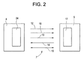
- FIG. 2 shows a diagrammatic block diagram of the locking system with a diagram for transmitting the signals
- FIG. 3 shows a block diagram of an electric steering lock arranged in the locking system
- FIG. 4 shows a more detailed diagram of the steering lock from FIG. 3 .
- a motor vehicle 1 with the authorized user 2 can be seen in FIG. 1 .
- the motor vehicle 1 is provided with a locking system 3 in the form of a door locking system which comprises a first device 4 in the form of a control device and an associated second device 5 .
- the second device 5 is in the form of an electronic key, an identification (ID) transmitter, a chip card, a smart card or the like.
- the second device 5 is in the possession of the authorized user 2 and so the latter has access to the motor vehicle 1 within an effective area 8 .
- the first device 4 has at least two states, the car doors 6 being locked in the first state and being unlocked in the second state.
- the two devices 4 , 5 have means for transmitting and/or receiving signals 7 by means of an electromagnetic carrier wave. At least one of these signals 7 , which are transmitted between the second device 5 and the first device 4 , is a coded electromagnetic operating signal 15 (see FIG. 2 ).
- the coded operating signal 15 is used to authenticate the second device 5 so that, when the second device 5 is authorized following positive evaluation of the transmitted operating signal 15 , the state of the first device 4 can be changed.
- the coded operating signal 15 is transmitted when the authorized user 2 operates the door handle 16 on the car door 6 or approaches the door handle 16 .
- the car doors 6 are unlocked according to the operation-independent keyless entry functionality.
- the coded operating signal 15 may also be transmitted just as well automatically without involvement of the user 2 as soon as the latter enters the effective area 8 but this is not considered in any more detail below. If the user closes the car doors 6 from the outside, the car doors 6 are automatically locked. The car doors 6 may be locked automatically just as well after the user has left the effective area 8 .
- remote-controllable unlocking and locking of the car doors 6 which can be triggered by the user 2 using operating elements on the second device 5 which are in the form of buttons, is also possible in addition to the keyless entry functionality in order to allow the user 2 to have operation-dependent authorization to access the motor vehicle 1 .
- the central locking system for the car doors 6 can be disabled and/or enabled and the trunk lid can be opened by manually operating the operating elements by virtue of corresponding coded operating signals 15 being transmitted from the second device 5 to the first device 4 .
- the locking system 3 also determines the drive authorization for the motor vehicle 1 .
- the first device 4 likewise unlocks and/or locks the electric steering lock 9 diagrammatically indicated in FIG. 1 according to the two states.
- Some other functionally relevant part of the motor vehicle 1 can be controlled just as well by the first device 4 in a corresponding manner.
- an immobilizer, the engine controller or the like may be enabled and/or disabled thereby.
- the coded operating signal 15 for authenticating the second device 5 is transmitted when the authorized user 2 is in the motor vehicle 1 and operates a start/stop switch 11 . The starting operation or the like of the motor vehicle 1 is thus triggered according to the KeylessGo functionality.
- the first device 4 first of all uses a transmitter/receiver 24 , as a means for transmitting and/or receiving signals, to transmit a first electromagnetic signal 12 , which is referred to as a wake-up signal, for the associated second device 5 .
- a first electromagnetic signal 12 which is referred to as a wake-up signal
- the second device 5 is changed from a quiescent state with a reduced power requirement to an activated state for intended operation.
- the first device 4 then transmits at least one further, third electromagnetic signal 13 which is also referred to as an area delimiting signal below.
- the associated second device 5 can thus determine its location with respect to the first device 4 .
- the second device 5 determines whether the second device 5 is on the outside of the motor vehicle 1 and, if appropriate, the location on the exterior 23 and/or in the interior 22 of the motor vehicle 1 at which second device 5 is situated.
- the second device 5 uses a transmitter/receiver 17 to transmit a fourth signal 14 , which comprises the information relating to the location determined and is also referred to as a response signal below, to the first device 4 .
- the fifth electromagnetic signal is then finally transmitted, in the form of a coded electromagnetic operating signal 15 , between the first and second devices 4 , 5 using the transmitters/receivers 24 , 17 for the purpose of authentication.
- the signal 15 may comprise, in particular, a plurality of signal elements and may be transmitted between the two devices 4 , 5 using bidirectional communication. Reference is also made to DE 43 40 260 A1 with regard to further details of bidirectional communication per se.
- the wake-up signal 12 may contain, for example, an identifier of the motor vehicle type. After the wake-up signal 12 has been received, all second devices 5 which are in the effective area 8 and belong to the same motor vehicle type are first of all activated.
- the first device 4 transmits a second electromagnetic signal 18 , as a selection signal, to the second device 5 between the first signal 12 and the third signal 13 , as can be seen in more detail from FIG. 2 .
- the second signal 18 contains information relating to the more detailed identity of the motor vehicle 1 .
- only the second devices 5 which are actually associated with the first device 4 remain in the activated state. However, second devices which are in the activated state and are not associated with the motor vehicle 1 are returned to the quiescent state.
- the electric steering lock 9 diagrammatically shown in FIG. 1 has a movable locking element 10 which, according to a first position, can be brought into locking engagement with a latched-in position 26 on the steering shaft 25 in the steering wheel column and, according to a second position, can be brought out of locking engagement with latched-in position 26 .
- the steering lock 9 has a drive 27 which comprises an electric motor, for example, and is intended to move the locking element 10 between the two positions.
- the drive 27 is supplied with electrical voltage by the battery in the motor vehicle 1 .
- electronics 28 for controlling the drive 27 are arranged in the steering lock 9 .
- the drive 27 for moving the locking element 10 into the respective position, but at least into the second unlocking position can be controlled by the electronics 28 .
- the electronics 28 comprise a microprocessor 30 which controls the operating sequences of the electric steering lock 9 in an appropriate manner.
- the electronics 28 can thus generate the signals which are required for drive authorization and are provided at corresponding outputs 31 of the steering lock 9 which are denoted KL (terminal) 15 , KL 50 etc.
- the electric steering lock 9 is a largely closed system which operates independently and without involvement of a further control unit, with the result that the electronics 28 autonomously control the drive 27 using corresponding drivers 33 (see FIG. 3 ).
- a coprocessor 32 in the electronics 28 interacts with the microprocessor 30 in a redundant manner in order to ensure that the safety criteria are met.
- the electric steering lock 9 also has a BUS module 34 in order to allow communication via the BUS system in the motor vehicle 1 .
- the arrangement of the electric steering lock 9 which operates in an intrinsically safe manner, in the locking system 3 can be seen in more detail in FIG. 3 .
- Those signals which are used to trigger functions which can otherwise be achieved by an electric ignition lock are generated in the electronics 28 of the steering lock 9 .
- the terminal signals of the ignition lock for example the so-called terminal 15 , terminal 50 etc., which enable the switching-on of electrical loads, such as the car radio or the like, are thus simulated in the electronics 28 according to FIG. 3 .
- the electronics 28 generate the key position signals 35 , the position switches being simulated using electrical signals which are then passed to the terminal control system 36 .
- the drive 27 is operated independently and thus without the signals which are otherwise output by the ignition lock via the drivers 33 using the microprocessor 30 and the coprocessor 32 , as a result of which keyless control is autonomously effected in the electric steering lock 9 .
- the electronics 28 and the second device 5 interact with a transmitter and/or receiver 24 , 17 using electromagnetic signals 7 .
- the two devices 4 , 5 generate random numbers and control a cryptological sequence 40 (see FIG. 3 ).
- the first device 4 may interact in an appropriate manner with a combination instrument 37 in the dash board of the motor vehicle 1 .
- the associated transmitter and/or receiver 24 may also be integrated in the electric steering lock 9 if desired, but this is not shown in any more detail in FIG. 3 .
- an antenna 38 for controlling the low-frequency (LF) signals for waking up and/or locating the second device 5 may be connected to the electric steering lock 9 by means of appropriate antenna interfaces 39 and, if desired, may also be integrated in the steering lock.
- signals may also be transmitted using a transponder 29 which is used as a type of antenna.
- the start/stop pushbutton 11 which interacts with the electronics 28 is preferably arranged in an installation space of the motor vehicle 1 where the locking cylinder of the electric ignition lock, which is now dispensed with, would otherwise be situated.
- the locking system 3 according to FIG. 3 also provides the access authorization, which is provided using the door handles 16 , in a type of keyless entry functionality in the motor vehicle 1 .
- a steering lock 9 according to the invention may thus also be used in other vehicles such as motorcycles, construction machinery, watercraft or the like.
Abstract
Description
Claims (15)
Applications Claiming Priority (4)
| Application Number | Priority Date | Filing Date | Title |
|---|---|---|---|
| DE102006018175 | 2006-04-18 | ||
| DE102006018175.1 | 2006-04-18 | ||
| DE102006018175 | 2006-04-18 | ||
| PCT/DE2007/000679 WO2007118469A1 (en) | 2006-04-18 | 2007-04-17 | Electric steering lock, in particular for a motor vehicle |
Related Parent Applications (1)
| Application Number | Title | Priority Date | Filing Date |
|---|---|---|---|
| PCT/DE2007/000679 Continuation WO2007118469A1 (en) | 2006-04-18 | 2007-04-17 | Electric steering lock, in particular for a motor vehicle |
Publications (2)
| Publication Number | Publication Date |
|---|---|
| US20090133453A1 US20090133453A1 (en) | 2009-05-28 |
| US7932627B2 true US7932627B2 (en) | 2011-04-26 |
Family
ID=38121623
Family Applications (1)
| Application Number | Title | Priority Date | Filing Date |
|---|---|---|---|
| US12/252,426 Active US7932627B2 (en) | 2006-04-18 | 2008-10-16 | Electric steering lock, in particular for a motor vehicle |
Country Status (6)
| Country | Link |
|---|---|
| US (1) | US7932627B2 (en) |
| EP (1) | EP2007610B1 (en) |
| CN (1) | CN101506008B (en) |
| ES (1) | ES2560639T3 (en) |
| RU (1) | RU2421351C2 (en) |
| WO (1) | WO2007118469A1 (en) |
Families Citing this family (8)
| Publication number | Priority date | Publication date | Assignee | Title |
|---|---|---|---|---|
| ATE547298T1 (en) * | 2006-09-20 | 2012-03-15 | Marquardt Gmbh | LOCKING SYSTEM, PARTICULARLY FOR A MOTOR VEHICLE |
| CN101941412A (en) * | 2010-07-30 | 2011-01-12 | 奇瑞汽车股份有限公司 | Automobile log-in/starting system and intelligent vehicle remote control and control method thereof |
| DE102011054437A1 (en) * | 2011-10-12 | 2013-04-18 | Huf Hülsbeck & Fürst Gmbh & Co. Kg | Device for a safety system of a motor vehicle with an autonomous, independently of the motor vehicle provided electronics |
| US10400735B2 (en) * | 2012-05-04 | 2019-09-03 | Light Wave Technology Inc. | System and method for remote starting a vehicle equipped with a smart start system |
| CN103661244B (en) * | 2012-09-21 | 2016-08-10 | 上海通用汽车有限公司 | A kind of one-touch startup system and startup method |
| CA2852866A1 (en) * | 2013-05-29 | 2014-11-29 | Lightwave Technology Inc. | System and method for keyless entry and remote starting vehicle with an oem remote embedded in vehicle |
| CN108569335B (en) * | 2018-04-26 | 2021-09-28 | 奇瑞汽车股份有限公司 | Control method of electric steering system |
| DE102019005815A1 (en) * | 2019-08-21 | 2021-02-25 | Marquardt Gmbh | Locking system, in particular for a motor vehicle |
Citations (12)
| Publication number | Priority date | Publication date | Assignee | Title |
|---|---|---|---|---|
| DE3739172C1 (en) | 1987-11-19 | 1989-02-09 | Daimler Benz Ag | Locking system for motor vehicles |
| EP1072487A1 (en) | 1999-07-30 | 2001-01-31 | FIAT AUTO S.p.A. | A system for enabling the use of a motor vehicle |
| DE10059991A1 (en) | 2000-12-02 | 2002-06-06 | Bosch Gmbh Robert | Device for the keyless operation of a motor vehicle |
| DE10202332A1 (en) | 2002-01-23 | 2003-07-24 | Daimler Chrysler Ag | Locking system for keyless entry-go vehicle access irrespective of circumstances uses a programmed changeable identification transmitter held by a user. |
| DE10202330A1 (en) | 2002-01-23 | 2003-07-24 | Marquardt Gmbh | Locking system for vehicle access/driver authorization with keyless entry-go vehicle access irrespective of circumstances uses a programmed changeable identification transmitter held by a user. |
| EP1504972A1 (en) | 2003-08-08 | 2005-02-09 | Kabushiki Kaisha Tokai Rika Denki Seisakusho | Engine start Controller |
| DE102004001904A1 (en) | 2004-01-14 | 2005-08-04 | Marquardt Gmbh | Remote control locking system for road vehicle incorporates alarm system alerting authorized driver of attempt by unauthorized person to hack into electronically controlled vehicle lock |
| DE102005031997A1 (en) | 2004-07-10 | 2006-02-09 | Marquardt Gmbh | Locking system for motor vehicle has transmitter of first control device allocated to at least two areas of vehicle, and operating component for release of signal from first control device is allocated to each aforesaid area |
| DE102005003082A1 (en) | 2005-01-22 | 2006-07-27 | Preiss, Harald | Stand for e.g. notice boards comprises vertical tube, into which board support fits, sliding sleeve mounted on to this carrying three radial legs with wheels at ends and lever on one leg raising wheels above base plate |
| US7375440B2 (en) * | 2002-08-29 | 2008-05-20 | Kabushiki Kaisha Tokai Rika Denki Seisakusho | Vehicle electronic key system |
| US7498688B2 (en) * | 2004-09-30 | 2009-03-03 | Denso Corporation | Engine start control system for vehicle |
| US7576636B2 (en) * | 2002-09-18 | 2009-08-18 | Daimler Ag | Driver authorization system |
-
2007
- 2007-04-17 EP EP07722237.0A patent/EP2007610B1/en active Active
- 2007-04-17 WO PCT/DE2007/000679 patent/WO2007118469A1/en active Application Filing
- 2007-04-17 CN CN2007800136673A patent/CN101506008B/en active Active
- 2007-04-17 RU RU2008145511A patent/RU2421351C2/en active
- 2007-04-17 ES ES07722237.0T patent/ES2560639T3/en active Active
-
2008
- 2008-10-16 US US12/252,426 patent/US7932627B2/en active Active
Patent Citations (15)
| Publication number | Priority date | Publication date | Assignee | Title |
|---|---|---|---|---|
| DE3739172C1 (en) | 1987-11-19 | 1989-02-09 | Daimler Benz Ag | Locking system for motor vehicles |
| EP1072487A1 (en) | 1999-07-30 | 2001-01-31 | FIAT AUTO S.p.A. | A system for enabling the use of a motor vehicle |
| DE10059991A1 (en) | 2000-12-02 | 2002-06-06 | Bosch Gmbh Robert | Device for the keyless operation of a motor vehicle |
| US20040046639A1 (en) | 2000-12-02 | 2004-03-11 | Elmar Giehler | Device for operating a motor vehicle without a key |
| DE10202332A1 (en) | 2002-01-23 | 2003-07-24 | Daimler Chrysler Ag | Locking system for keyless entry-go vehicle access irrespective of circumstances uses a programmed changeable identification transmitter held by a user. |
| DE10202330A1 (en) | 2002-01-23 | 2003-07-24 | Marquardt Gmbh | Locking system for vehicle access/driver authorization with keyless entry-go vehicle access irrespective of circumstances uses a programmed changeable identification transmitter held by a user. |
| US6963794B2 (en) | 2002-01-23 | 2005-11-08 | Daimlerchrysler Ag | Locking system for a motor vehicle |
| US7375440B2 (en) * | 2002-08-29 | 2008-05-20 | Kabushiki Kaisha Tokai Rika Denki Seisakusho | Vehicle electronic key system |
| US7576636B2 (en) * | 2002-09-18 | 2009-08-18 | Daimler Ag | Driver authorization system |
| EP1504972A1 (en) | 2003-08-08 | 2005-02-09 | Kabushiki Kaisha Tokai Rika Denki Seisakusho | Engine start Controller |
| US7254466B2 (en) * | 2003-08-08 | 2007-08-07 | Kabushiki Kaisha Tokai Rika Denki Seisakusho | Engine start controller |
| DE102004001904A1 (en) | 2004-01-14 | 2005-08-04 | Marquardt Gmbh | Remote control locking system for road vehicle incorporates alarm system alerting authorized driver of attempt by unauthorized person to hack into electronically controlled vehicle lock |
| DE102005031997A1 (en) | 2004-07-10 | 2006-02-09 | Marquardt Gmbh | Locking system for motor vehicle has transmitter of first control device allocated to at least two areas of vehicle, and operating component for release of signal from first control device is allocated to each aforesaid area |
| US7498688B2 (en) * | 2004-09-30 | 2009-03-03 | Denso Corporation | Engine start control system for vehicle |
| DE102005003082A1 (en) | 2005-01-22 | 2006-07-27 | Preiss, Harald | Stand for e.g. notice boards comprises vertical tube, into which board support fits, sliding sleeve mounted on to this carrying three radial legs with wheels at ends and lever on one leg raising wheels above base plate |
Also Published As
| Publication number | Publication date |
|---|---|
| ES2560639T3 (en) | 2016-02-22 |
| US20090133453A1 (en) | 2009-05-28 |
| EP2007610A1 (en) | 2008-12-31 |
| CN101506008A (en) | 2009-08-12 |
| RU2008145511A (en) | 2010-05-27 |
| EP2007610B1 (en) | 2015-10-28 |
| WO2007118469A1 (en) | 2007-10-25 |
| RU2421351C2 (en) | 2011-06-20 |
| CN101506008B (en) | 2013-04-10 |
Similar Documents
| Publication | Publication Date | Title |
|---|---|---|
| US7932627B2 (en) | Electric steering lock, in particular for a motor vehicle | |
| JP6499864B2 (en) | Energy supply circuit for electrical components | |
| US9600947B2 (en) | Lock system, in particular for a motor vehicle | |
| US6127922A (en) | Vehicle security system with remote systems control | |
| US7394350B2 (en) | Power-saving on-vehicle controller | |
| US6437683B1 (en) | Keyless security entry control method for motor vehicles | |
| US8437916B2 (en) | Universal garage door opener and appliance control system | |
| US10449931B2 (en) | Lock system and apparatus for a motor vehicle with secondary energy storage and transmission for emergency operation | |
| US6963794B2 (en) | Locking system for a motor vehicle | |
| US7010402B2 (en) | Vehicle control system including multi-vehicle controller using vehicle code learning index and related methods | |
| CA2540192C (en) | Remote controlling key for vehicle | |
| WO2001025572A1 (en) | Vehicle access system including an electronic key and a valet mode of operation | |
| US20100052849A1 (en) | Switching device | |
| US7667571B2 (en) | Locking system, in particular for a motor vehicle | |
| US20090153296A1 (en) | Keyless control system | |
| JP4742979B2 (en) | Keyless entry system | |
| US20190152440A1 (en) | Method for controlling access to a vehicle according to different strategies | |
| US6538559B1 (en) | Remote control apparatus and remote control method | |
| US20080231416A1 (en) | Latency reduction in remote signal communication system | |
| US6838976B2 (en) | Keyless access control device and method for motor vehicles | |
| US6850154B2 (en) | Method and device for protecting motor vehicles against theft | |
| JP4600296B2 (en) | Electronic key system for vehicles | |
| EP3388291A1 (en) | Automotive entry and engine ignition control | |
| JPH0821136A (en) | Door lock device for automobile | |
| ITTO940492A1 (en) | ANTI-THEFT SYSTEM DISTRIBUTED FOR A VEHICLE. |
Legal Events
| Date | Code | Title | Description |
|---|---|---|---|
| AS | Assignment |
Owner name: MARQUARDT GMBH, GERMANY Free format text: ASSIGNMENT OF ASSIGNORS INTEREST;ASSIGNORS:MUELLER, KARL;STAUSS, GERD;MAIER, RALF;AND OTHERS;REEL/FRAME:022197/0206;SIGNING DATES FROM 20081121 TO 20081217 Owner name: VOLKSWAGEN AG, GERMANY Free format text: ASSIGNMENT OF ASSIGNORS INTEREST;ASSIGNORS:MUELLER, KARL;STAUSS, GERD;MAIER, RALF;AND OTHERS;REEL/FRAME:022197/0206;SIGNING DATES FROM 20081121 TO 20081217 Owner name: MARQUARDT GMBH, GERMANY Free format text: ASSIGNMENT OF ASSIGNORS INTEREST;ASSIGNORS:MUELLER, KARL;STAUSS, GERD;MAIER, RALF;AND OTHERS;SIGNING DATES FROM 20081121 TO 20081217;REEL/FRAME:022197/0206 Owner name: VOLKSWAGEN AG, GERMANY Free format text: ASSIGNMENT OF ASSIGNORS INTEREST;ASSIGNORS:MUELLER, KARL;STAUSS, GERD;MAIER, RALF;AND OTHERS;SIGNING DATES FROM 20081121 TO 20081217;REEL/FRAME:022197/0206 |
|
| FEPP | Fee payment procedure |
Free format text: PAYOR NUMBER ASSIGNED (ORIGINAL EVENT CODE: ASPN); ENTITY STATUS OF PATENT OWNER: LARGE ENTITY |
|
| FEPP | Fee payment procedure |
Free format text: PAYOR NUMBER ASSIGNED (ORIGINAL EVENT CODE: ASPN); ENTITY STATUS OF PATENT OWNER: LARGE ENTITY Free format text: PAYER NUMBER DE-ASSIGNED (ORIGINAL EVENT CODE: RMPN); ENTITY STATUS OF PATENT OWNER: LARGE ENTITY |
|
| STCF | Information on status: patent grant |
Free format text: PATENTED CASE |
|
| FPAY | Fee payment |
Year of fee payment: 4 |
|
| MAFP | Maintenance fee payment |
Free format text: PAYMENT OF MAINTENANCE FEE, 8TH YEAR, LARGE ENTITY (ORIGINAL EVENT CODE: M1552); ENTITY STATUS OF PATENT OWNER: LARGE ENTITY Year of fee payment: 8 |
|
| AS | Assignment |
Owner name: VOLKSWAGEN AKTIENGESELLSCHAFT, GERMANY Free format text: ASSIGNMENT OF ASSIGNORS INTEREST;ASSIGNOR:VOLKSWAGEN AG;REEL/FRAME:061168/0468 Effective date: 20220920 Owner name: VOLKSWAGEN AKTIENGESELLSCHAFT, GERMANY Free format text: ASSIGNMENT OF ASSIGNORS INTEREST;ASSIGNOR:MARQUARDT GMBH;REEL/FRAME:061168/0311 Effective date: 20220305 |
|
| MAFP | Maintenance fee payment |
Free format text: PAYMENT OF MAINTENANCE FEE, 12TH YEAR, LARGE ENTITY (ORIGINAL EVENT CODE: M1553); ENTITY STATUS OF PATENT OWNER: LARGE ENTITY Year of fee payment: 12 |