EP1408321A1 - Pollen sensor and method - Google Patents
Pollen sensor and method Download PDFInfo
- Publication number
- EP1408321A1 EP1408321A1 EP20030022585 EP03022585A EP1408321A1 EP 1408321 A1 EP1408321 A1 EP 1408321A1 EP 20030022585 EP20030022585 EP 20030022585 EP 03022585 A EP03022585 A EP 03022585A EP 1408321 A1 EP1408321 A1 EP 1408321A1
- Authority
- EP
- European Patent Office
- Prior art keywords
- particles
- light beam
- polarized
- intensity
- pollen
- Prior art date
- Legal status (The legal status is an assumption and is not a legal conclusion. Google has not performed a legal analysis and makes no representation as to the accuracy of the status listed.)
- Granted
Links
- 238000000034 method Methods 0.000 title claims abstract description 18
- 239000002245 particle Substances 0.000 claims abstract description 114
- 230000010287 polarization Effects 0.000 claims abstract description 35
- 238000001514 detection method Methods 0.000 claims abstract description 27
- 238000005286 illumination Methods 0.000 claims abstract description 17
- 239000004816 latex Substances 0.000 description 7
- 229920000126 latex Polymers 0.000 description 7
- 238000005259 measurement Methods 0.000 description 6
- 239000004033 plastic Substances 0.000 description 5
- 239000004793 Polystyrene Substances 0.000 description 4
- 238000006243 chemical reaction Methods 0.000 description 4
- 230000003287 optical effect Effects 0.000 description 4
- 229920002223 polystyrene Polymers 0.000 description 4
- 241000218692 Cryptomeria Species 0.000 description 3
- 238000011179 visual inspection Methods 0.000 description 3
- 238000011109 contamination Methods 0.000 description 2
- 239000006185 dispersion Substances 0.000 description 2
- 239000011521 glass Substances 0.000 description 2
- 238000005070 sampling Methods 0.000 description 2
- 239000004065 semiconductor Substances 0.000 description 2
- 201000010105 allergic rhinitis Diseases 0.000 description 1
- 238000004458 analytical method Methods 0.000 description 1
- 230000000052 comparative effect Effects 0.000 description 1
- 230000007812 deficiency Effects 0.000 description 1
- 238000010586 diagram Methods 0.000 description 1
- 230000000694 effects Effects 0.000 description 1
- 238000010223 real-time analysis Methods 0.000 description 1
Images


Classifications
-
- G—PHYSICS
- G01—MEASURING; TESTING
- G01N—INVESTIGATING OR ANALYSING MATERIALS BY DETERMINING THEIR CHEMICAL OR PHYSICAL PROPERTIES
- G01N21/00—Investigating or analysing materials by the use of optical means, i.e. using sub-millimetre waves, infrared, visible or ultraviolet light
- G01N21/17—Systems in which incident light is modified in accordance with the properties of the material investigated
- G01N21/21—Polarisation-affecting properties
-
- G—PHYSICS
- G01—MEASURING; TESTING
- G01N—INVESTIGATING OR ANALYSING MATERIALS BY DETERMINING THEIR CHEMICAL OR PHYSICAL PROPERTIES
- G01N15/00—Investigating characteristics of particles; Investigating permeability, pore-volume or surface-area of porous materials
- G01N15/02—Investigating particle size or size distribution
- G01N15/0205—Investigating particle size or size distribution by optical means
- G01N15/0211—Investigating a scatter or diffraction pattern
-
- G—PHYSICS
- G01—MEASURING; TESTING
- G01N—INVESTIGATING OR ANALYSING MATERIALS BY DETERMINING THEIR CHEMICAL OR PHYSICAL PROPERTIES
- G01N15/00—Investigating characteristics of particles; Investigating permeability, pore-volume or surface-area of porous materials
- G01N2015/0042—Investigating dispersion of solids
- G01N2015/0046—Investigating dispersion of solids in gas, e.g. smoke
Definitions
- the present invention relates to a pollen sensor and method for detecting pollen particles and discriminating pollen particles floating in air from other particles on a real time basis. More specifically, the pollen sensor and method detects pollen particles floating in air, which can be a cause for pollenosis.
- a microscope has been used to detect the number of pollen particles floating in air using a visual inspection process in which a glass plate is exposed to air for some time to collect pollen particles.
- the glass plate is stained, followed by a skilled technician's counting by visual inspection the stained particles through his or her microscope (hereinafter referred to as the "microscope method").
- the above microscope method is a lengthy time consuming process requiring advanced skills to count the stained pollen particles by visual inspection.
- the microscope method does not permit pollen particles to be detected on a real time basis which is a significant drawback.
- the place for taking measurements using a microscope is also very limited, which is another drawback.
- a similar detection device is described in Japanese Patent Publication No. 2001-83079 which is capable of measuring floating particles in real time. This device cannot discriminate pollen particles from other particles passed through the detection zone when the volume of air blown into the detection zone is increased. Accordingly, this device has the same deficiencies as the pollen sensor described in Japanese Patent No. 3113720.
- the present invention is based on the discovery that the degree of polarization of scattered light beams from pollen particles is smaller than the degree of polarization from other floating particles even of the same particle size as pollen particles. This principal is used in the pollen sensor of the present invention to discriminate pollen particles from other floating particles.
- the pollen sensor of the present invention comprises: an illumination portion for illuminating particles floating in air using light beams polarized in a given direction; a first receiver for selectively measuring the intensity (Ip) of a light beam from a detection zone polarized parallel to the light beam polarized in a given direction from the illumination portion with the light beam selected from a group of light beams scattered by the floating particles; a second receiver for selectively measuring the intensity (Is) of light beam from a detection zone polarized perpendicular to the light beam polarized in a given direction from the illumination portion with the light beam selected from a group of light beams scattered by the floating particles and means for discriminating pollen particles from other floating particles including means for computing the degree of polarization of such particles as an arithmetic value from the intensity (Ip) of the polarized light beam detected by the first receiver and the intensity (Is) of the polarized light beam detected by the second receiver.
- the pollen sensor comprises: an illumination portion for illuminating particles floating in air using a light beam polarized in a given direction; a first receiver for measuring the intensity (I) of a light beam corresponding to the dispersion of the light beam scattered by the floating particles; a second receiver for selectively measuring the intensity (Is) of light beams polarized perpendicular to light illuminated by the illumination portion from a group of light beams scattered by the floating particles; means for discriminating pollen particles from other floating particles from the degree of polarization of such particles computed from the intensity (I) of the scattered light beam detected by the first receiver and the intensity (Is) of the polarized light beam detected by the second receiver.
- the degree of polarization can be computed either as an arithmetic value using (Ip), which is the intensity of light polarized parallel to the incident polarizing direction and (Is) which is the intensity of light polarized in a direction perpendicular to the incident polarization direction or as an arithmetic value using (I), which is the intensity for all polarized scattered light, and (Is) which is the intensity of light polarized in a direction perpendicular to the incident polarizing direction.
- the degree of polarization may be expressed by the formula (Ip-Is)/(Ip+Is) wherein (Ip) is the intensity of the light beam polarized in the incident polarizing direction and (Is) is the intensity of the light beam polarized perpendicular to the incident polarizing direction.
- the degree of polarization may be expressed by the formula (I-Is)/I wherein (I) is the intensity for all polarized scattered light and (Is) is the intensity of a light beam polarized perpendicular to the incident polarizing direction.
- any person can readily discriminate pollen particles from other floating particles on a real time basis and can perform a real time analysis of the pollen count. Furthermore, the present invention can discriminate pollen particles form other particles notwithstanding the amount of air blown into the detection zone or the number of floating particles passed through the detection zone.
- the present invention can accurately discriminate pollen particles from other particles even though the luminous energy from a light source in the illumination portion weakens over time and / or lens contamination occurs reducing the luminous energy that reaches the detection zone.
- the pollen sensor and method of the present invention permits simultaneous passage of two or more floating particles with a reliable output even if there is a reduction of light volume from light source due to its life problem, or a reduction of dispersion light volume due to the dirt of a lens.
- the pollen sensor of the present invention comprises a shielding housing 14 which forms a confined area for housing an illuminating portion 1 containing a light beam generating source 4, preferably a semiconductor laser diode.
- the light beam generating source generates a light beam 20 for illuminating one or more particles 25 ( Figure 3) floating in air within the detection zone F.
- the light beam 20 has a direction of polarization 22 perpendicular to the plane of the page of Figure 2 as is diagrammatically illustrated in Figure 3.
- the pollen sensor further comprises a first receiver 2 having a photodiode 7 aligned in the scattering polarizing direction of the light beam 20, preferably at 60 degrees to the incident optical axis "OA" for measuring the intensity (Ip) of light beams polarized in a direction parallel to the incident polarizing direction of light selected from a group of light beams scattered by the floating particles; a second receiver 3 having a photodiode 10 provided in the scattering polarizing direction, preferably at 60 degrees to the incident optical axis "OA", for measuring the intensity (Is) of light beams in a direction 23 which is polarized perpendicular to the light beam illuminated by the illumination portion selected from a group of light beams scattered by the floating particles and an electronic circuit 32 for discriminating pollen particles from other floating particles.
- a first receiver 2 having a photodiode 7 aligned in the scattering polarizing direction of the light beam 20, preferably at 60 degrees to the incident optical axis "OA" for measuring the intensity (Ip
- the pollen sensor also comprises an air blow port 13 located at the bottom of the shielding housing 14 to direct sampling air drawn from the atmosphere by a fan 26 through the air blow port 13 into the shielding housing 14.
- the sampling air is introduced into the sensor in a direction from the bottom to the top of the plane containing Figure 2.
- Any semiconductor laser diode 4 may be used such as, e.g., an RLD 65 MZT 1, manufactured by Rohm for generating the light beam 20.
- the laser diode 4 is contained in an illuminating portion 1 supported in the housing 14 which, as shown in Figures 1 and 2, also includes a polarizing filter 5 and a plastic lens 6.
- a polarizing filter 5 is the HN 38, manufactured by Polaroid.
- the polarizing filter 5 has a polarizing axis in a direction perpendicular to the plane containing Figure 2 and is perpendicular to the plastic lens 6.
- Lens 6 is arranged in the illuminating portion of the sensor in such a manner that the laser light transmitted through the polarizing filter 5 forms parallel beams of light energy upon reaching the detection zone (F).
- the detection zone F lies at the intersection of the light path through the filter 6 and the light path of the randomly polarized light 24 to the first and second receiver 2 and 3 respectively.
- the polarizing axis of the polarizing filter 8 is perpendicular to the plane containing Figure 2 in the same manner as that of the polarizing filter 5 in the illuminating portion 1 of the pollen sensor.
- a polarizing filter 11 such as e.g., HN 38, manufactured by Polaroid
- a photodiode 10 such as, e.g., S 2506-02 manufactured by Hamamatsu Photonics for measuring light transmitted through the polarizing filter 11.
- the polarizing axis of the polarizing filter 11 is set perpendicular to the polarizing axis of polarizing filter 5, which is in parallel to the plane containing Figure 2.
- the photoelectric current conversion signal Ip and the photoelectric current conversion signal Is are fed to current voltage conversion circuits 35 and 36 respectively, to form voltage signals Vp and Vs respectively.
- the computation of the degree of polarization permits a determination to be readily made in accordance with the present invention as to whether the detected particles constitute pollen particles or other floating particles. It has been determined that when the computation of the degree of polarization (Ip - Is)/(Ip + Is) is in the range of 0.35 - 0.75 the detected particles constitute pollen particles. This range of 0.35 - 0.75 may vary with changes in the angle of alignment between the photodiode of the first and second receivers and the axis of the illuminating light beam generating portion (optical axis) which, for the preferred embodiment of the present invention, has been set at 60°.
- Figures 5-8 are histograms illustrating the comparative measurement of the degree of polarization for 20 - micron polystyrene latex particles, 30 - micron polystyrene latex particles, 40 - micron polystyrene latex particles, and for Japanese cedar pollen particles respectively.
- the X-axis shows the degree of polarization (Ip - Is)/(Ip + Is); and the Y-axis shows the frequency of particle detection.
- the range of measurement of the degree of polarization for the latex particles falls between 0.7-1.0 and for the Japanese cedar pollen particles as shown in Figure 8 is between 0.35 - 0.75 permitting a possible overlap in measurement in the range between 0.70 - 0.75.
- FIG 9 is a plan view illustrating the configuration of another embodiment of the pollen sensor of the present invention.
- the pollen sensor in this embodiment excludes filter 8 from the first receiver 2 and is otherwise identical to the pollen sensor in Figure 2.
- the components constituting the same elements as is shown in the sensor of Figure 2 have the same reference symbols.
- light beams scattered from floating particles directly reach photodiode 7 without passing through a polarizing filter.
- an output photoelectric conversion signal I will correspond to the intensity of the scattered light beams for all polarizing directions.
- the degree of polarization for this embodiment is computed in accordance with the formula: (I-Is)/I.
- the degree of polarization falls within the range of 0.35 - 0.75, the particles constitute pollen particles as in the first embodiment and for the same reasons.
- the photodiode 7 in the first receiver 2 and the photodiode 10 in the second receiver 3 were each aligned in the scattering polarization direction at an angle of 60° to the incident optical axis OA, it is not essential to this invention for the angle to be limited to a 60° and, in fact, any angle within a range of 0° - 90° may be used.
- the scattered beams that enter a lens may be separated into a component that is in parallel to the plane containing Figure 2 and into another component that is perpendicular to the plane containing Figure 2, utilizing a polarized beam splitter, followed by analysis of each component using a photodiode. The degree of polarization can thus be obtained as well.
Landscapes
- Chemical & Material Sciences (AREA)
- Physics & Mathematics (AREA)
- Health & Medical Sciences (AREA)
- Life Sciences & Earth Sciences (AREA)
- Analytical Chemistry (AREA)
- Biochemistry (AREA)
- General Health & Medical Sciences (AREA)
- General Physics & Mathematics (AREA)
- Immunology (AREA)
- Pathology (AREA)
- Dispersion Chemistry (AREA)
- Investigating Or Analysing Materials By Optical Means (AREA)
Abstract
Description
- The present invention relates to a pollen sensor and method for detecting pollen particles and discriminating pollen particles floating in air from other particles on a real time basis. More specifically, the pollen sensor and method detects pollen particles floating in air, which can be a cause for pollenosis.
- Conventionally, a microscope has been used to detect the number of pollen particles floating in air using a visual inspection process in which a glass plate is exposed to air for some time to collect pollen particles. The glass plate is stained, followed by a skilled technician's counting by visual inspection the stained particles through his or her microscope (hereinafter referred to as the "microscope method").
- The above microscope method is a lengthy time consuming process requiring advanced skills to count the stained pollen particles by visual inspection. In addition, the microscope method does not permit pollen particles to be detected on a real time basis which is a significant drawback. The place for taking measurements using a microscope is also very limited, which is another drawback.
- It is also known to detect pollen particles on a real time basis utilizing polarized light. This alternate method is disclosed in Japanese Patent No. 3113720 and in Japanese Patent Publication No. 2001-83079. The pollen detector described in Japanese Patent No. 3113720 does not require the expertise that the microscope method requires, and the measurement result can be obtained anywhere on a real time basis. Nevertheless, the quantity of pollen particles floating in air is so small that to increase the available number of pollen particles, a large volume of air should be blown into the detection zone. However, this also increases the probability of other floating particles being simultaneously passed into the detection zone. Since the pollen detector described in Japanese Patent No. 3113720 cannot discriminate pollen particles from other floating particles, the pollen detector is prone to error. Moreover, either a decrease in luminous energy emitted from the light source over time or lens contamination will reduce the intensity of the scattered light beams, making it even more difficult to discriminate pollen particles from other particles.
- A similar detection device is described in Japanese Patent Publication No. 2001-83079 which is capable of measuring floating particles in real time. This device cannot discriminate pollen particles from other particles passed through the detection zone when the volume of air blown into the detection zone is increased. Accordingly, this device has the same deficiencies as the pollen sensor described in Japanese Patent No. 3113720.
- It is an object of the present invention to provide a pollen sensor and method of detection capable of accurately counting the number of pollen particles floating in the air in a detection zone on a real time basis. Another object of the present invention is to provide a pollen sensor and method for accurately discriminating pollen particles from other floating particles even if the luminous energy emitted by the illumination portion is weakened over time.
- The present invention is based on the discovery that the degree of polarization of scattered light beams from pollen particles is smaller than the degree of polarization from other floating particles even of the same particle size as pollen particles. This principal is used in the pollen sensor of the present invention to discriminate pollen particles from other floating particles.
- The pollen sensor of the present invention comprises: an illumination portion for illuminating particles floating in air using light beams polarized in a given direction; a first receiver for selectively measuring the intensity (Ip) of a light beam from a detection zone polarized parallel to the light beam polarized in a given direction from the illumination portion with the light beam selected from a group of light beams scattered by the floating particles; a second receiver for selectively measuring the intensity (Is) of light beam from a detection zone polarized perpendicular to the light beam polarized in a given direction from the illumination portion with the light beam selected from a group of light beams scattered by the floating particles and means for discriminating pollen particles from other floating particles including means for computing the degree of polarization of such particles as an arithmetic value from the intensity (Ip) of the polarized light beam detected by the first receiver and the intensity (Is) of the polarized light beam detected by the second receiver.
- In accordance with another embodiment of the present invention, the pollen sensor comprises: an illumination portion for illuminating particles floating in air using a light beam polarized in a given direction; a first receiver for measuring the intensity (I) of a light beam corresponding to the dispersion of the light beam scattered by the floating particles; a second receiver for selectively measuring the intensity (Is) of light beams polarized perpendicular to light illuminated by the illumination portion from a group of light beams scattered by the floating particles; means for discriminating pollen particles from other floating particles from the degree of polarization of such particles computed from the intensity (I) of the scattered light beam detected by the first receiver and the intensity (Is) of the polarized light beam detected by the second receiver.
- When the incident light is linearly polarized (hereinafter referred to as the "incident polarizing direction"), the degree of polarization can be computed either as an arithmetic value using (Ip), which is the intensity of light polarized parallel to the incident polarizing direction and (Is) which is the intensity of light polarized in a direction perpendicular to the incident polarization direction or as an arithmetic value using (I), which is the intensity for all polarized scattered light, and (Is) which is the intensity of light polarized in a direction perpendicular to the incident polarizing direction.
- More specifically, for the first embodiment the degree of polarization may be expressed by the formula (Ip-Is)/(Ip+Is) wherein (Ip) is the intensity of the light beam polarized in the incident polarizing direction and (Is) is the intensity of the light beam polarized perpendicular to the incident polarizing direction. Alternatively, for the second embodiment the degree of polarization may be expressed by the formula (I-Is)/I wherein (I) is the intensity for all polarized scattered light and (Is) is the intensity of a light beam polarized perpendicular to the incident polarizing direction. A comparison of the degree of polarization of the pollen particles to that of other floating particles shows that the degree of polarization for pollen particles is smaller than that of other floating particles. This characteristic permits the pollen sensor to discriminate pollen particles from other floating particles.
- Utilizing the pollen sensor and method of the present invention, any person can readily discriminate pollen particles from other floating particles on a real time basis and can perform a real time analysis of the pollen count. Furthermore, the present invention can discriminate pollen particles form other particles notwithstanding the amount of air blown into the detection zone or the number of floating particles passed through the detection zone.
- In addition, the present invention can accurately discriminate pollen particles from other particles even though the luminous energy from a light source in the illumination portion weakens over time and / or lens contamination occurs reducing the luminous energy that reaches the detection zone. Thus, the pollen sensor and method of the present invention permits simultaneous passage of two or more floating particles with a reliable output even if there is a reduction of light volume from light source due to its life problem, or a reduction of dispersion light volume due to the dirt of a lens.
-
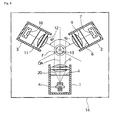
- Figure 1 is a cross-sectional view of the pollen sensor of the present invention;
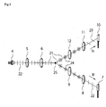
- Figure 2 is a plan view of the pollen sensor of Figure 1, looking downwardly, part of the housing uncovered to show the arrangement of the first and second receiver to the illumination portion;
- Figure 3 is a diagrammatic view of the method of detecting the light intensity (Is) and light intensity (Ip) components of light scattered by the floating particles in accordance with the present invention;
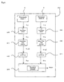
- Figure 4 is a circuit schematic block diagram of the preferred means for discriminating pollen particles from other particles in the pollen sensor of Figures 1 and 2 respectively;
- Figure 5 is a histogram illustrating the degree of polarization of 20-micron polystyrene latex particles;
- Figure 6 is a histogram illustrating the degree of polarization of 30-micron latex particles;
- Figure 7 is a histogram illustrating the degree of polarization of 40-micron latex particles;
- Figure 8 is a histogram illustrating the degree of polarization of Japanese cedar pollen particles; and
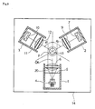
- Figure 9 is a plan view of a pollen sensor similar to that of Figure 2, showing another embodiment of the present invention.
-
- The present invention is described hereinafter with reference to Figures 1-9 of the drawings. As shown in Figures 1 and 2, the pollen sensor of the present invention comprises a
shielding housing 14 which forms a confined area for housing anilluminating portion 1 containing a lightbeam generating source 4, preferably a semiconductor laser diode. The light beam generating source generates alight beam 20 for illuminating one or more particles 25 (Figure 3) floating in air within the detection zone F. Thelight beam 20 has a direction ofpolarization 22 perpendicular to the plane of the page of Figure 2 as is diagrammatically illustrated in Figure 3. The pollen sensor further comprises afirst receiver 2 having aphotodiode 7 aligned in the scattering polarizing direction of thelight beam 20, preferably at 60 degrees to the incident optical axis "OA" for measuring the intensity (Ip) of light beams polarized in a direction parallel to the incident polarizing direction of light selected from a group of light beams scattered by the floating particles; asecond receiver 3 having aphotodiode 10 provided in the scattering polarizing direction, preferably at 60 degrees to the incident optical axis "OA", for measuring the intensity (Is) of light beams in adirection 23 which is polarized perpendicular to the light beam illuminated by the illumination portion selected from a group of light beams scattered by the floating particles and anelectronic circuit 32 for discriminating pollen particles from other floating particles. - The pollen sensor also comprises an
air blow port 13 located at the bottom of theshielding housing 14 to direct sampling air drawn from the atmosphere by afan 26 through theair blow port 13 into theshielding housing 14. The sampling air is introduced into the sensor in a direction from the bottom to the top of the plane containing Figure 2. - Any
semiconductor laser diode 4 may be used such as, e.g., an RLD 65 MZT 1, manufactured by Rohm for generating thelight beam 20. Thelaser diode 4 is contained in anilluminating portion 1 supported in thehousing 14 which, as shown in Figures 1 and 2, also includes a polarizingfilter 5 and aplastic lens 6. One example of a polarizingfilter 5 is the HN 38, manufactured by Polaroid. The polarizingfilter 5 has a polarizing axis in a direction perpendicular to the plane containing Figure 2 and is perpendicular to theplastic lens 6. Theplastic lens 6 has a focal length "f" of preferably 10 mm, i.e. f = 10 mm.Lens 6 is arranged in the illuminating portion of the sensor in such a manner that the laser light transmitted through the polarizingfilter 5 forms parallel beams of light energy upon reaching the detection zone (F). The detection zone F lies at the intersection of the light path through thefilter 6 and the light path of the randomly polarizedlight 24 to the first andsecond receiver - The
first receiver 2 includes a polarizingfilter 8 such as, e.g., HN 38, manufactured by Polaroid, a plastic lens 9 (f=10mm) and aphotodiode 7 such as, e.g., S 2506 - 02 manufactured by Hamamatsu Photonics for measuring light transmitted through the polarizingfilter 8. The polarizing axis of the polarizingfilter 8 is perpendicular to the plane containing Figure 2 in the same manner as that of the polarizingfilter 5 in theilluminating portion 1 of the pollen sensor. - The
second receiver 3 includes a polarizingfilter 11 such as e.g., HN 38, manufactured by Polaroid, a plastic lens 12 (f=10 mm) and aphotodiode 10 such as, e.g., S 2506-02 manufactured by Hamamatsu Photonics for measuring light transmitted through the polarizingfilter 11. The polarizing axis of the polarizingfilter 11 is set perpendicular to the polarizing axis of polarizingfilter 5, which is in parallel to the plane containing Figure 2. - As shown in Figure 4, the photoelectric current conversion signal Ip and the photoelectric current conversion signal Is are fed to current
voltage conversion circuits 35 and 36 respectively, to form voltage signals Vp and Vs respectively. The voltage signals Vp and Vs are amplified by therespective amplifiers digital converters 40 and 41 and fed into amicroprocessor 39 for computing the degree of polarization as an arithmetic value utilizing (Ip), the intensity of polarized light detected by the receiver [2] and (Is), the intensity of polarized light detected by the second receiver [3] in accordance with the following formula: - The computation of the degree of polarization, as defined above, permits a determination to be readily made in accordance with the present invention as to whether the detected particles constitute pollen particles or other floating particles. It has been determined that when the computation of the degree of polarization (Ip - Is)/(Ip + Is) is in the range of 0.35 - 0.75 the detected particles constitute pollen particles. This range of 0.35 - 0.75 may vary with changes in the angle of alignment between the photodiode of the first and second receivers and the axis of the illuminating light beam generating portion (optical axis) which, for the preferred embodiment of the present invention, has been set at 60°. Figures 5-8 are histograms illustrating the comparative measurement of the degree of polarization for 20 - micron polystyrene latex particles, 30 - micron polystyrene latex particles, 40 - micron polystyrene latex particles, and for Japanese cedar pollen particles respectively. The X-axis shows the degree of polarization (Ip - Is)/(Ip + Is); and the Y-axis shows the frequency of particle detection. As is apparent from Figures 5-7 the range of measurement of the degree of polarization for the latex particles falls between 0.7-1.0 and for the Japanese cedar pollen particles as shown in Figure 8 is between 0.35 - 0.75 permitting a possible overlap in measurement in the range between 0.70 - 0.75. Although some overlap in the measurement of the degree of polarization may exist between pollen particles and other floating particles, the degree of overlap consists of only about 5% of the total particle count and is therefore minimal. Thus, pollen particles are readily distinguishable from other floating particles using the pollen sensor and method of the present invention .
- Figure 9 is a plan view illustrating the configuration of another embodiment of the pollen sensor of the present invention. The pollen sensor in this embodiment excludes
filter 8 from thefirst receiver 2 and is otherwise identical to the pollen sensor in Figure 2. In Figure 9, the components constituting the same elements as is shown in the sensor of Figure 2 have the same reference symbols. In this embodiment, light beams scattered from floating particles directly reachphotodiode 7 without passing through a polarizing filter. As a result, an output photoelectric conversion signal I will correspond to the intensity of the scattered light beams for all polarizing directions. Accordingly, the degree of polarization for this embodiment is computed in accordance with the formula: (I-Is)/I. When the degree of polarization falls within the range of 0.35 - 0.75, the particles constitute pollen particles as in the first embodiment and for the same reasons. - It should be understood that although the
photodiode 7 in thefirst receiver 2 and thephotodiode 10 in thesecond receiver 3 were each aligned in the scattering polarization direction at an angle of 60° to the incident optical axis OA, it is not essential to this invention for the angle to be limited to a 60° and, in fact, any angle within a range of 0° - 90° may be used. Alternately, the scattered beams that enter a lens may be separated into a component that is in parallel to the plane containing Figure 2 and into another component that is perpendicular to the plane containing Figure 2, utilizing a polarized beam splitter, followed by analysis of each component using a photodiode. The degree of polarization can thus be obtained as well.
Claims (5)
- A pollen sensor comprising:an illumination portion for generating a light beam for illuminating particles floating in air in a detection zone of the pollen sensor, with the light beam polarized in a given direction;a first receiver for selectively measuring the intensity (Ip) of light beams from the detection zone polarized parallel to the light beam polarized in said given direction from said illumination portion with the light beam selected from a group of light beams scattered by said floating particles;a second receiver for measuring the intensity (Is) of light beams from the detection zone polarized perpendicular to the light beam polarized in said given direction from the illumination portion with the light beam selected from the group of light beams scattered by the floating particles; andmeans for discriminating pollen particles from other floating particles including means for computing the degree of polarization of such particles as an arithmetic value from the intensity (Ip) of the polarized light beam detected by the first receiver and the intensity (Is) of the polarized light beam detected by the second receiver.
- The pollen sensor as set forth in Claim 1, wherein said degree of polarization is computed in accordance with the following formula:
- A pollen sensor comprising:an illumination portion for generating a light beam for illuminating particles floating in air in a detection zone of the pollen sensor with the light beam polarized in a given direction;a first receiver for measuring the intensity (I) of a light beam scattered by said floating particles; anda second receiver for selectively measuring the intensity (Is) of a light beam polarized in a direction perpendicular to light illuminated by the illumination portion with the light beam selected from a group of light beams scattered by the floating particles; andmeans for discriminating pollen particles from other floating particles in accordance with the degree of polarization of such particles based upon the intensity (I) of the scattered light beam detected by the first receiver and the intensity (Is) of the polarized light beam detected by the second receiver.
- The pollen sensor as set forth in Claim 3, wherein said degree of polarization is computed from the following formula:
- A method for detecting the presence of pollen particles floating in air in a detection zone and for discriminating between pollen particles and other particles on a real time basis comprising the steps of:generating a light beam for illuminating particles floating in air in a detection zone with the light beam being polarized in a given direction;selectively measuring the intensity (I) or (Ip) of a light beam from the detection zone polarized parallel to the light beam polarized in said given direction from said illumination portion with the light beam selected from a group of light beams scattered by said floating particles in said detection zone;selectively measuring the intensity (Is) of a light beam from the detection zone polarized perpendicular to the light beam polarized in said given direction from said illumination portion with the light beam selected from the group of light beams scattered by the floating particles in said detection zone; andmeasuring the degree of polarization of such particles as an arithmetic value from the intensity (Ip) of the polarized light beam detected by the first receiver and the intensity (Is) of the polarized light beam detected by the second receiver for distinguishing between pollen particles and other particles.
Applications Claiming Priority (2)
| Application Number | Priority Date | Filing Date | Title |
|---|---|---|---|
| JP2002289881A JP3720799B2 (en) | 2002-10-02 | 2002-10-02 | Pollen sensor |
| JP2002289881 | 2002-10-02 |
Publications (2)
| Publication Number | Publication Date |
|---|---|
| EP1408321A1 true EP1408321A1 (en) | 2004-04-14 |
| EP1408321B1 EP1408321B1 (en) | 2006-11-02 |
Family
ID=32025450
Family Applications (1)
| Application Number | Title | Priority Date | Filing Date |
|---|---|---|---|
| EP03022585A Expired - Lifetime EP1408321B1 (en) | 2002-10-02 | 2003-10-02 | Pollen sensor and method |
Country Status (4)
| Country | Link |
|---|---|
| US (1) | US7119900B2 (en) |
| EP (1) | EP1408321B1 (en) |
| JP (1) | JP3720799B2 (en) |
| DE (1) | DE60309411T2 (en) |
Families Citing this family (20)
| Publication number | Priority date | Publication date | Assignee | Title |
|---|---|---|---|---|
| ITPC20050045A1 (en) * | 2005-08-04 | 2007-02-05 | Numerouno Ricerche Srl | METHOD AND DEVICE FOR DETECTION OF FALSE DOCUMENTS AND BANK NOTES |
| US20100081956A1 (en) * | 2008-09-30 | 2010-04-01 | Searete Llc, A Limited Liability Corporation Of The State Of Delaware | Method, composition, and system to control pH in pulmonary tissue of a subject |
| JP5717136B2 (en) * | 2011-05-06 | 2015-05-13 | 学校法人福岡大学 | Particle measuring device |
| KR101154236B1 (en) | 2011-09-21 | 2012-06-18 | (주)랩코 | Measuring apparatus of slim type of floating particles in air |
| US20140142456A1 (en) * | 2012-04-27 | 2014-05-22 | Control A Plus, LLC | Environmental and patient monitor for providing activity recommendations |
| EP3854450A1 (en) | 2012-09-05 | 2021-07-28 | electroCore, Inc. | Non-invasive vagal nerve stimulation to treat disorders |
| JP2014202690A (en) * | 2013-04-09 | 2014-10-27 | ソニー株式会社 | Navigation device and storage medium |
| JP2016133435A (en) * | 2015-01-20 | 2016-07-25 | 株式会社リコー | Optical apparatus and information processing system |
| CN107923836B (en) * | 2015-06-17 | 2020-12-01 | 贝克顿·迪金森公司 | Optical detector diffuser cap assembly with removable diffuser rod and method of use |
| EP4215900A1 (en) | 2015-09-23 | 2023-07-26 | Malvern Panalytical Limited | Particle characterisation |
| US10241043B2 (en) | 2015-12-14 | 2019-03-26 | Mitsubishi Electric Corporation | Micro object detection apparatus |
| GB201604460D0 (en) | 2016-03-16 | 2016-04-27 | Malvern Instr Ltd | Dynamic light scattering |
| US9851291B2 (en) * | 2016-05-02 | 2017-12-26 | Hamilton Associates, Inc. | Realtime optical method and system for detecting and classifying biological and non-biological particles |
| FR3055966A1 (en) * | 2016-09-09 | 2018-03-16 | Valeo Systemes Thermiques | DEVICE FOR DETECTING PARTICULATE MATTER IN AN AIR FLOW FOR A MOTOR VEHICLE |
| DE102016221989A1 (en) | 2016-11-09 | 2018-05-09 | Robert Bosch Gmbh | Particle sensor with at least two laser Doppler sensors |
| EP3379232A1 (en) * | 2017-03-23 | 2018-09-26 | Malvern Panalytical Limited | Particle characterisation |
| KR102153640B1 (en) * | 2018-01-09 | 2020-09-08 | 채규욱 | Optical fine dust sensor |
| EP3815066B1 (en) | 2018-06-29 | 2023-03-01 | Carrier Corporation | Multipurpose air monitoring device |
| US11016024B2 (en) * | 2019-02-19 | 2021-05-25 | Kla Corporation | Air scattering standard for light scattering based optical instruments and tools |
| FR3105829B1 (en) * | 2019-12-30 | 2021-12-03 | Lify Air | DEVICE FOR DETECTION OF THE PRESENCE OF POLLENS IN THE AIR, AND CORRESPONDING DETECTION METHOD |
Citations (7)
| Publication number | Priority date | Publication date | Assignee | Title |
|---|---|---|---|---|
| US3612689A (en) * | 1967-04-10 | 1971-10-12 | American Standard Inc | Suspended particle concentration determination using polarized light |
| US4134679A (en) * | 1976-11-05 | 1979-01-16 | Leeds & Northrup Company | Determining the volume and the volume distribution of suspended small particles |
| US4362387A (en) * | 1980-08-22 | 1982-12-07 | Rockwell International Corporation | Method and apparatus for measuring visibility from the polarization properties of the daylight sky |
| JPH05240768A (en) * | 1992-02-26 | 1993-09-17 | Shinei Kk | Pollen detector |
| JP2001083079A (en) * | 1999-09-17 | 2001-03-30 | Stanley Electric Co Ltd | Measuring device for dust, smoke, etc. |
| GB2368390A (en) * | 2000-03-16 | 2002-05-01 | Univ Loughborough | Analysing a plurality of objects such as particles in a fluid |
| US20020186375A1 (en) * | 2001-05-01 | 2002-12-12 | Asbury Charles L. | Device and methods for detecting samples in a flow cytometer independent of variations in fluorescence polarization |
Family Cites Families (5)
| Publication number | Priority date | Publication date | Assignee | Title |
|---|---|---|---|---|
| US4341471A (en) * | 1979-01-02 | 1982-07-27 | Coulter Electronics, Inc. | Apparatus and method for measuring the distribution of radiant energy produced in particle investigating systems |
| US4989978A (en) * | 1986-04-04 | 1991-02-05 | Technicon Instruments Corporation | Method and apparatus for determining the count per unit volume of particles |
| NL8601000A (en) * | 1986-04-21 | 1987-11-16 | Jan Greve T H Twente Afdeling | THE USE OF POLARIZED LIGHT IN FLOW CYTOMETRY. |
| JP3258882B2 (en) * | 1995-11-24 | 2002-02-18 | 株式会社堀場製作所 | Particle size distribution analyzer |
| US6320650B1 (en) * | 1999-12-20 | 2001-11-20 | Eastman Kodak Company | Positioning apparatus for image capturing apparatus |
-
2002
- 2002-10-02 JP JP2002289881A patent/JP3720799B2/en not_active Expired - Fee Related
-
2003
- 2003-10-02 DE DE60309411T patent/DE60309411T2/en not_active Expired - Fee Related
- 2003-10-02 US US10/678,194 patent/US7119900B2/en not_active Expired - Fee Related
- 2003-10-02 EP EP03022585A patent/EP1408321B1/en not_active Expired - Lifetime
Patent Citations (7)
| Publication number | Priority date | Publication date | Assignee | Title |
|---|---|---|---|---|
| US3612689A (en) * | 1967-04-10 | 1971-10-12 | American Standard Inc | Suspended particle concentration determination using polarized light |
| US4134679A (en) * | 1976-11-05 | 1979-01-16 | Leeds & Northrup Company | Determining the volume and the volume distribution of suspended small particles |
| US4362387A (en) * | 1980-08-22 | 1982-12-07 | Rockwell International Corporation | Method and apparatus for measuring visibility from the polarization properties of the daylight sky |
| JPH05240768A (en) * | 1992-02-26 | 1993-09-17 | Shinei Kk | Pollen detector |
| JP2001083079A (en) * | 1999-09-17 | 2001-03-30 | Stanley Electric Co Ltd | Measuring device for dust, smoke, etc. |
| GB2368390A (en) * | 2000-03-16 | 2002-05-01 | Univ Loughborough | Analysing a plurality of objects such as particles in a fluid |
| US20020186375A1 (en) * | 2001-05-01 | 2002-12-12 | Asbury Charles L. | Device and methods for detecting samples in a flow cytometer independent of variations in fluorescence polarization |
Non-Patent Citations (2)
| Title |
|---|
| PATENT ABSTRACTS OF JAPAN vol. 017, no. 699 (P - 1665) 21 December 1993 (1993-12-21) * |
| PATENT ABSTRACTS OF JAPAN vol. 2000, no. 20 10 July 2001 (2001-07-10) * |
Also Published As
| Publication number | Publication date |
|---|---|
| US20040066513A1 (en) | 2004-04-08 |
| US7119900B2 (en) | 2006-10-10 |
| JP2004125602A (en) | 2004-04-22 |
| EP1408321B1 (en) | 2006-11-02 |
| DE60309411T2 (en) | 2007-08-30 |
| JP3720799B2 (en) | 2005-11-30 |
| DE60309411D1 (en) | 2006-12-14 |
Similar Documents
| Publication | Publication Date | Title |
|---|---|---|
| EP1408321B1 (en) | Pollen sensor and method | |
| US7292338B2 (en) | Particle detection apparatus and particle detection method used therefor | |
| US5872361A (en) | Turbidimeter with non-imaging optical concentrator | |
| JP4817442B2 (en) | Optical system for particle analyzer and particle analyzer using the same | |
| CN109459438A (en) | A defect detection device and method | |
| CN112485167A (en) | Optical system of particle analyzer | |
| JP2002062267A (en) | Defect inspection device | |
| CN101424568B (en) | Light measuring device and scanning optical system | |
| JP3113720B2 (en) | Pollen detector | |
| JPH10176995A (en) | Transparent object inspection method and apparatus | |
| JP3053096B2 (en) | Foreign object detection method and device | |
| KR101685703B1 (en) | Alien substance inspection apparatus and inspection method | |
| JPH04301769A (en) | Liquid sensor | |
| JP3046504B2 (en) | Particle measuring method and particle measuring device | |
| JPH06273344A (en) | Defect inspection device and defect inspection method | |
| JPS58115346A (en) | Discriminating apparatus of kind of blood corpuscle | |
| JPH05240770A (en) | Particle counter | |
| SU1121602A1 (en) | Device for measuring sizes and counting concentration of aerosol particles | |
| JPH08178830A (en) | Detector | |
| JPS6193932A (en) | particle analyzer | |
| JP2004184395A (en) | Pollen sensor | |
| JPH04132940A (en) | grain analyzer | |
| KR100220229B1 (en) | Optical axis identification apparatus and method | |
| JPH02138851A (en) | particle measuring device | |
| JPS63153449A (en) | Particle counter |
Legal Events
| Date | Code | Title | Description |
|---|---|---|---|
| PUAI | Public reference made under article 153(3) epc to a published international application that has entered the european phase |
Free format text: ORIGINAL CODE: 0009012 |
|
| AK | Designated contracting states |
Kind code of ref document: A1 Designated state(s): AT BE BG CH CY CZ DE DK EE ES FI FR GB GR HU IE IT LI LU MC NL PT RO SE SI SK TR |
|
| AX | Request for extension of the european patent |
Extension state: AL LT LV MK |
|
| 17P | Request for examination filed |
Effective date: 20041004 |
|
| AKX | Designation fees paid |
Designated state(s): DE FR GB NL |
|
| 17Q | First examination report despatched |
Effective date: 20050228 |
|
| GRAP | Despatch of communication of intention to grant a patent |
Free format text: ORIGINAL CODE: EPIDOSNIGR1 |
|
| GRAS | Grant fee paid |
Free format text: ORIGINAL CODE: EPIDOSNIGR3 |
|
| GRAA | (expected) grant |
Free format text: ORIGINAL CODE: 0009210 |
|
| AK | Designated contracting states |
Kind code of ref document: B1 Designated state(s): DE FR GB NL |
|
| REG | Reference to a national code |
Ref country code: GB Ref legal event code: FG4D |
|
| REF | Corresponds to: |
Ref document number: 60309411 Country of ref document: DE Date of ref document: 20061214 Kind code of ref document: P |
|
| ET | Fr: translation filed | ||
| PLBE | No opposition filed within time limit |
Free format text: ORIGINAL CODE: 0009261 |
|
| STAA | Information on the status of an ep patent application or granted ep patent |
Free format text: STATUS: NO OPPOSITION FILED WITHIN TIME LIMIT |
|
| 26N | No opposition filed |
Effective date: 20070803 |
|
| PGFP | Annual fee paid to national office [announced via postgrant information from national office to epo] |
Ref country code: GB Payment date: 20090318 Year of fee payment: 6 |
|
| PGFP | Annual fee paid to national office [announced via postgrant information from national office to epo] |
Ref country code: DE Payment date: 20090317 Year of fee payment: 6 |
|
| PGFP | Annual fee paid to national office [announced via postgrant information from national office to epo] |
Ref country code: FR Payment date: 20090316 Year of fee payment: 6 |
|
| PGFP | Annual fee paid to national office [announced via postgrant information from national office to epo] |
Ref country code: NL Payment date: 20090320 Year of fee payment: 7 |
|
| REG | Reference to a national code |
Ref country code: FR Ref legal event code: ST Effective date: 20100630 |
|
| PG25 | Lapsed in a contracting state [announced via postgrant information from national office to epo] |
Ref country code: DE Free format text: LAPSE BECAUSE OF NON-PAYMENT OF DUE FEES Effective date: 20100501 Ref country code: FR Free format text: LAPSE BECAUSE OF NON-PAYMENT OF DUE FEES Effective date: 20091102 |
|
| PG25 | Lapsed in a contracting state [announced via postgrant information from national office to epo] |
Ref country code: GB Free format text: LAPSE BECAUSE OF NON-PAYMENT OF DUE FEES Effective date: 20091002 |
|
| REG | Reference to a national code |
Ref country code: NL Ref legal event code: V1 Effective date: 20110501 |
|
| PG25 | Lapsed in a contracting state [announced via postgrant information from national office to epo] |
Ref country code: NL Free format text: LAPSE BECAUSE OF NON-PAYMENT OF DUE FEES Effective date: 20110501 |