EP1408199A1 - Leak resistant vane cluster - Google Patents
Leak resistant vane cluster Download PDFInfo
- Publication number
- EP1408199A1 EP1408199A1 EP20030256227 EP03256227A EP1408199A1 EP 1408199 A1 EP1408199 A1 EP 1408199A1 EP 20030256227 EP20030256227 EP 20030256227 EP 03256227 A EP03256227 A EP 03256227A EP 1408199 A1 EP1408199 A1 EP 1408199A1
- Authority
- EP
- European Patent Office
- Prior art keywords
- slot
- cluster
- shroud
- nonlinear
- shrouds
- Prior art date
- Legal status (The legal status is an assumption and is not a legal conclusion. Google has not performed a legal analysis and makes no representation as to the accuracy of the status listed.)
- Granted
Links
- 238000003754 machining Methods 0.000 claims description 3
- 239000012530 fluid Substances 0.000 abstract description 8
- 238000004519 manufacturing process Methods 0.000 description 6
- 239000000463 material Substances 0.000 description 2
- 238000000034 method Methods 0.000 description 2
- 238000003491 array Methods 0.000 description 1
- 230000000295 complement effect Effects 0.000 description 1
- 238000010276 construction Methods 0.000 description 1
- 238000001816 cooling Methods 0.000 description 1
- 230000007423 decrease Effects 0.000 description 1
- 238000010438 heat treatment Methods 0.000 description 1
- 239000012535 impurity Substances 0.000 description 1
- 238000007789 sealing Methods 0.000 description 1
Images

Classifications
-
- F—MECHANICAL ENGINEERING; LIGHTING; HEATING; WEAPONS; BLASTING
- F04—POSITIVE - DISPLACEMENT MACHINES FOR LIQUIDS; PUMPS FOR LIQUIDS OR ELASTIC FLUIDS
- F04D—NON-POSITIVE-DISPLACEMENT PUMPS
- F04D29/00—Details, component parts, or accessories
- F04D29/40—Casings; Connections of working fluid
- F04D29/52—Casings; Connections of working fluid for axial pumps
- F04D29/54—Fluid-guiding means, e.g. diffusers
- F04D29/541—Specially adapted for elastic fluid pumps
- F04D29/542—Bladed diffusers
-
- F—MECHANICAL ENGINEERING; LIGHTING; HEATING; WEAPONS; BLASTING
- F01—MACHINES OR ENGINES IN GENERAL; ENGINE PLANTS IN GENERAL; STEAM ENGINES
- F01D—NON-POSITIVE DISPLACEMENT MACHINES OR ENGINES, e.g. STEAM TURBINES
- F01D11/00—Preventing or minimising internal leakage of working-fluid, e.g. between stages
- F01D11/005—Sealing means between non relatively rotating elements
-
- F—MECHANICAL ENGINEERING; LIGHTING; HEATING; WEAPONS; BLASTING
- F01—MACHINES OR ENGINES IN GENERAL; ENGINE PLANTS IN GENERAL; STEAM ENGINES
- F01D—NON-POSITIVE DISPLACEMENT MACHINES OR ENGINES, e.g. STEAM TURBINES
- F01D5/00—Blades; Blade-carrying members; Heating, heat-insulating, cooling or antivibration means on the blades or the members
- F01D5/12—Blades
- F01D5/22—Blade-to-blade connections, e.g. for damping vibrations
- F01D5/225—Blade-to-blade connections, e.g. for damping vibrations by shrouding
-
- F—MECHANICAL ENGINEERING; LIGHTING; HEATING; WEAPONS; BLASTING
- F01—MACHINES OR ENGINES IN GENERAL; ENGINE PLANTS IN GENERAL; STEAM ENGINES
- F01D—NON-POSITIVE DISPLACEMENT MACHINES OR ENGINES, e.g. STEAM TURBINES
- F01D5/00—Blades; Blade-carrying members; Heating, heat-insulating, cooling or antivibration means on the blades or the members
- F01D5/30—Fixing blades to rotors; Blade roots ; Blade spacers
- F01D5/3007—Fixing blades to rotors; Blade roots ; Blade spacers of axial insertion type
- F01D5/3015—Fixing blades to rotors; Blade roots ; Blade spacers of axial insertion type with side plates
-
- F—MECHANICAL ENGINEERING; LIGHTING; HEATING; WEAPONS; BLASTING
- F01—MACHINES OR ENGINES IN GENERAL; ENGINE PLANTS IN GENERAL; STEAM ENGINES
- F01D—NON-POSITIVE DISPLACEMENT MACHINES OR ENGINES, e.g. STEAM TURBINES
- F01D9/00—Stators
- F01D9/02—Nozzles; Nozzle boxes; Stator blades; Guide conduits, e.g. individual nozzles
- F01D9/04—Nozzles; Nozzle boxes; Stator blades; Guide conduits, e.g. individual nozzles forming ring or sector
-
- F—MECHANICAL ENGINEERING; LIGHTING; HEATING; WEAPONS; BLASTING
- F05—INDEXING SCHEMES RELATING TO ENGINES OR PUMPS IN VARIOUS SUBCLASSES OF CLASSES F01-F04
- F05D—INDEXING SCHEME FOR ASPECTS RELATING TO NON-POSITIVE-DISPLACEMENT MACHINES OR ENGINES, GAS-TURBINES OR JET-PROPULSION PLANTS
- F05D2230/00—Manufacture
- F05D2230/10—Manufacture by removing material
- F05D2230/12—Manufacture by removing material by spark erosion methods
-
- F—MECHANICAL ENGINEERING; LIGHTING; HEATING; WEAPONS; BLASTING
- F05—INDEXING SCHEMES RELATING TO ENGINES OR PUMPS IN VARIOUS SUBCLASSES OF CLASSES F01-F04
- F05D—INDEXING SCHEME FOR ASPECTS RELATING TO NON-POSITIVE-DISPLACEMENT MACHINES OR ENGINES, GAS-TURBINES OR JET-PROPULSION PLANTS
- F05D2240/00—Components
- F05D2240/55—Seals
-
- F—MECHANICAL ENGINEERING; LIGHTING; HEATING; WEAPONS; BLASTING
- F05—INDEXING SCHEMES RELATING TO ENGINES OR PUMPS IN VARIOUS SUBCLASSES OF CLASSES F01-F04
- F05D—INDEXING SCHEME FOR ASPECTS RELATING TO NON-POSITIVE-DISPLACEMENT MACHINES OR ENGINES, GAS-TURBINES OR JET-PROPULSION PLANTS
- F05D2250/00—Geometry
-
- F—MECHANICAL ENGINEERING; LIGHTING; HEATING; WEAPONS; BLASTING
- F05—INDEXING SCHEMES RELATING TO ENGINES OR PUMPS IN VARIOUS SUBCLASSES OF CLASSES F01-F04
- F05D—INDEXING SCHEME FOR ASPECTS RELATING TO NON-POSITIVE-DISPLACEMENT MACHINES OR ENGINES, GAS-TURBINES OR JET-PROPULSION PLANTS
- F05D2250/00—Geometry
- F05D2250/10—Two-dimensional
- F05D2250/18—Two-dimensional patterned
- F05D2250/183—Two-dimensional patterned zigzag
Definitions
- This invention relates to shrouded vane clusters of the type used in turbine engines, and particularly to a cluster with a leak resistant, segmented shroud.
- the compressor section of a typical gas turbine engine comprises a case circumscribing an engine axis and axially alternating arrays of stationary vanes and rotatable blades.
- Each vane array may be constructed of multiple vane clusters distributed circumferentially about the interior of the case with each cluster being supported by the case.
- Each vane cluster comprises a radially inner shroud, a radially outer shroud, and two or more airfoils extending between the shrouds.
- the inner and outer shrouds define the inner and outer boundaries of part of an annular flowpath for a working medium fluid.
- one of the two shrouds may be divided into segments by slots that sever the shroud at locations circumferentially intermediate two neighboring airfoils. Since the outer shroud of each cluster connects the cluster to the case, it is conventional to segment the inner shroud rather than the outer shroud. The slots reduce the risk of damage by allowing the shroud segments to expand and contract independently of each other.
- Wire EDM uses an electrically charged electrode in the form a wire wound around a source spool and extending to a take-up spool.
- the vane cluster shroud is exposed to the wire between the spools.
- the wire travels from the source spool to the takeup spool and simultaneously advances toward the shroud.
- the difference in electrical charge between the wire electrode and the shroud causes an electrical discharge that removes material from the shroud. As material is removed, the wire advances through the shroud until the slot is completely formed.
- shroud slots provide a path by which working medium fluid can leak out of the flowpath during engine operation or by which non-working medium fluid can leak into the flowpath. Leakage can be mitigated, to some extent, by using a small diameter EDM wire to cut a thin slot, i.e. one with a correspondingly narrow kerf.
- the use of thin EDM wire leads to increased machining time.
- thin EDM wire is more susceptible to breakage than thick EDM wire during the EDM operation.
- Thin EDM wire is also more likely than thick EDM wire to be stalled by the presence of minute particulate impurities trapped in the vane cluster.
- EDM equipment capable of using thin wire is more specialized than EDM equipment capable using thicker wire.
- a manufacturer may find it economically unattractive to invest in the more specialized, thin wire equipment. Accordingly, it may be desirable to avoid thin slots in favor of relatively wider slots.
- a vane cluster includes a shroud with a nonlinear slot extending therethrough to divide the shroud into thermally independent shroud segments.
- the slot is bordered by matching nonlinear surfaces that are easy and inexpensive to produce with conventional wire EDM equipment.
- the nonlinear slots effectively resist fluid leakage.
- a vane cluster for a turbine engine compressor includes a radially outer shroud 10 , a radially inner shroud 12 and two or more airfoils 14 extending radially or spanwisely between the shrouds.
- Hooks 16 at the axial extremities of the outer shroud facilitate its attachment to an engine case, not shown.
- Feet 18 at the axial extremities of the inner shroud accommodate an inner airseal, also not shown.
- the cluster extends circumferentially between lateral extremities 20 . When several such clusters are installed in a turbine engine, the shrouds define the radially inner and outer boundaries of a portion of an annular fluid flowpath 22 .
- the flowpath circumscribes an engine axis, not shown.
- the vane cluster itself is typically a cast metallic article finish machined to prescribed dimensions.
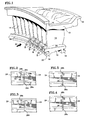
- the inner shroud 12 is divided into individual segments 24 by nonlinear slots 26 between circumferentially neighboring airfoils 14 .
- the slots are installed by wire EDM or other suitable process.
- Four different types of slots are depicted in Figure 1 , however only one type of slot would ordinarily be used in a given cluster.
- the leftmost portion of the inner shroud is depicted in its "as-cast" state, i.e. without slots.
- Each slot is nonlinear, but may comprise two or more straight line portions as seen best in Figures 2-4 .
- Each slot is bordered by a pair of matching surfaces, such as 28a, 28b .
- matching surfaces refers to surfaces that are substantially exact counterparts of each other, i.e. surfaces that complement each other. This is in contrast to the surfaces shown in US Patents 3,728,041, 3,970,318, and 5,167,485, all of which feature intra-slot recesses that render the adjacent slot surfaces non-matching.
- the nonlinear slot 26 comprises three straight line portions 26a, 26b, 26c , each of which has a juncture 32 with at least one of the other portions.
- Each juncture corresponds to a change of angular direction in the slot.
- one juncture 32 between slot portions 26a and 26b corresponds to an approximate 90 degree change of angular orientation from the radial direction to the lateral direction.
- the other juncture 32 between slot portions 26b and 26c corresponds to another change of approximately 90 degrees from lateral to radial.
- the accumulated angular change is therefore about 180 degrees.
- Figure 3 shows a variant in which the slot comprises three straight line portions and two junctures. Each juncture corresponds to an approximately 120 degree change of angular orientation for an accumulated angular change of about 240 degrees.
- Figure 4 shows a variant in which the slot comprises seven straight line portions and six junctures. Each juncture corresponds to an approximately 90 degree change of angular orientation for an accumulated angular change of about 540 degrees.
- the abrupt changes in angular orientation at the junctures 32 help resist fluid leakage through the slot and therefore permit the use of inexpensively installed, relatively wide slots that might otherwise be unsatisfactory.
- Each change of orientation increases the resistance to fluid leakage.
- larger and/or more abrupt changes are superior to smaller and/or less abrupt changes.
- a slot having only two straight line portions and one juncture can be used, it is believed that the most practical and cost effective slots are those with at least three straight line portions and two changes of orientation totaling at least about 180 degrees. A larger quantity of straight line portions would be expected to further increase leak resistance of the slot, but the correspondingly longer slot length would increase the time necessary to cut the slot using wire EDM.
- the tradeoff between leak resistance and manufacturing complexity is a matter for consideration by the designers and manufacturers of the vane cluster.
- the nonlinear slot need not be comprised of linear portions as in the above examples, but may instead be a curved slot having one or more radii of curvature.
- the average radius of curvature R may vary continuously along the length of the slot ( Figure 6 ) or may vary discontinuously ( Figure 7 ) thus defining one or more distinct junctures 32 between individual portions 26a, 26b of the slot.
- a slot may comprise both curved and straight line portions in combination. Since the leak resistance of a slot depends on the abruptness and quantity of directional changes, a smoothly curved slot may provide unsatisfactory leak resistance.
- a curved slot with an abrupt directional change is expected to be superior to a smooth curve, but may be more difficult to manufacture than a slot comprised of straight line portions.
- a curved slot having multiple, continuously varing radii of curvature is the serpentine slot of Figure 5 .
- the slots need not be installed circumferentially between each and every airfoil, but may instead be installed selectively, for example between every second or third airfoil, to achieve the desired degree of thermal independence.
- the cluster of Figure 1 is one sector of a single array or stage of vanes.
- the vane clusters comprise two or more circumferentially aligned sub-clusters, integral with each other but axially separated from each other by an interstage space.
- rotor blades extend radially into the interstage space.
- the invention includes such multi-stage clusters as well as the illustrated single stage cluster.
- the nonlinear geometry of the slot 26 may also be employed as the interface between the lateral extremities 20 of adjacent vane clusters.
- Such a construction includes inner and outer shrouds 10, 12 with at least one airfoil extending between the shrouds.
- the lateral extremities of at least one of the shrouds, e.g. inner shroud 12 has a nonlinear profile that matches a counterpart nonlinear profile on the extremity of a laterally adjacent vane cluster.
Landscapes
- Engineering & Computer Science (AREA)
- Mechanical Engineering (AREA)
- General Engineering & Computer Science (AREA)
- Structures Of Non-Positive Displacement Pumps (AREA)
- Turbine Rotor Nozzle Sealing (AREA)
- Electrical Discharge Machining, Electrochemical Machining, And Combined Machining (AREA)
Abstract
Description
- This invention relates to shrouded vane clusters of the type used in turbine engines, and particularly to a cluster with a leak resistant, segmented shroud.
- The compressor section of a typical gas turbine engine comprises a case circumscribing an engine axis and axially alternating arrays of stationary vanes and rotatable blades. Each vane array may be constructed of multiple vane clusters distributed circumferentially about the interior of the case with each cluster being supported by the case. Each vane cluster comprises a radially inner shroud, a radially outer shroud, and two or more airfoils extending between the shrouds. Collectively, the inner and outer shrouds define the inner and outer boundaries of part of an annular flowpath for a working medium fluid.
- During engine operation, the vane clusters are subject to nonuniform heating and cooling. The accompanying temperature gradients can cause damage by overstressing the clusters. To help alleviate these thermally induced stresses, one of the two shrouds may be divided into segments by slots that sever the shroud at locations circumferentially intermediate two neighboring airfoils. Since the outer shroud of each cluster connects the cluster to the case, it is conventional to segment the inner shroud rather than the outer shroud. The slots reduce the risk of damage by allowing the shroud segments to expand and contract independently of each other.
- One technique for forming the slots is wire electro-discharge machining (EDM). Wire EDM uses an electrically charged electrode in the form a wire wound around a source spool and extending to a take-up spool. The vane cluster shroud is exposed to the wire between the spools. During the EDM operation, the wire travels from the source spool to the takeup spool and simultaneously advances toward the shroud. The difference in electrical charge between the wire electrode and the shroud causes an electrical discharge that removes material from the shroud. As material is removed, the wire advances through the shroud until the slot is completely formed.
- One drawback of the shroud slots is that they provide a path by which working medium fluid can leak out of the flowpath during engine operation or by which non-working medium fluid can leak into the flowpath. Leakage can be mitigated, to some extent, by using a small diameter EDM wire to cut a thin slot, i.e. one with a correspondingly narrow kerf. However the use of thin EDM wire leads to increased machining time. Moreover, thin EDM wire is more susceptible to breakage than thick EDM wire during the EDM operation. Thin EDM wire is also more likely than thick EDM wire to be stalled by the presence of minute particulate impurities trapped in the vane cluster. Finally, commercially available EDM equipment capable of using thin wire is more specialized than EDM equipment capable using thicker wire. As a result, a manufacturer may find it economically unattractive to invest in the more specialized, thin wire equipment. Accordingly, it may be desirable to avoid thin slots in favor of relatively wider slots.
- One way to reduce leakage through a wide slot is to provide a recess in the interior of the slot and install a seal in the recess. US Patents 3,728,041, 3,970,318, and 5,167,485 show arrangements of this type. Although such seals may be easily installable between the shrouds of individual vanes, or between the circumferential extremities of adjacent vane clusters, they are not easily installable in the inter-airfoil shroud slots of an otherwise unitary vane cluster. In addition, forming the intra-slot recess increases manufacturing cost and decreases manufacturing throughput. Another possible way to mitigate leakage is to install an external seal, such as the sealing strip 78 shown in US Patent 4,422,827, to bridge across each slot. However such external seals also increase manufacturing cost.
- What is needed is a vane cluster with thermally independent shroud segments and which is economical and easy to manufacture.
- According to the invention, a vane cluster includes a shroud with a nonlinear slot extending therethrough to divide the shroud into thermally independent shroud segments. The slot is bordered by matching nonlinear surfaces that are easy and inexpensive to produce with conventional wire EDM equipment. The nonlinear slots effectively resist fluid leakage.
-
- Figure 1 is a perspective view of a vane cluster whose radially inner shroud is segmented by slots embraced by the present invention.
- Figures 2-5 are enlarged views of the slots shown in Figure 1.
- Figures 6-8 are enlarged views of slots having curved portions.
- Figure 9 is a view similar to Figure 1 showing a vane cluster with a nonlinear profile at the lateral extremities of its inner shroud.
-
- Referring to Figures 1-5, a vane cluster for a turbine engine compressor includes a radially
outer shroud 10, a radiallyinner shroud 12 and two ormore airfoils 14 extending radially or spanwisely between the shrouds.Hooks 16 at the axial extremities of the outer shroud facilitate its attachment to an engine case, not shown.Feet 18 at the axial extremities of the inner shroud accommodate an inner airseal, also not shown. The cluster extends circumferentially betweenlateral extremities 20. When several such clusters are installed in a turbine engine, the shrouds define the radially inner and outer boundaries of a portion of anannular fluid flowpath 22. The flowpath circumscribes an engine axis, not shown. The vane cluster itself is typically a cast metallic article finish machined to prescribed dimensions. - The
inner shroud 12 is divided intoindividual segments 24 bynonlinear slots 26 between circumferentially neighboringairfoils 14. The slots are installed by wire EDM or other suitable process. Four different types of slots are depicted in Figure 1, however only one type of slot would ordinarily be used in a given cluster. The leftmost portion of the inner shroud is depicted in its "as-cast" state, i.e. without slots. Each slot is nonlinear, but may comprise two or more straight line portions as seen best in Figures 2-4. Each slot is bordered by a pair of matching surfaces, such as 28a, 28b. As used herein, the term "matching" surfaces refers to surfaces that are substantially exact counterparts of each other, i.e. surfaces that complement each other. This is in contrast to the surfaces shown in US Patents 3,728,041, 3,970,318, and 5,167,485, all of which feature intra-slot recesses that render the adjacent slot surfaces non-matching. - Figures 2-5 show the four slots in greater detail. Referring first to Figure 2, the
nonlinear slot 26 comprises threestraight line portions juncture 32 with at least one of the other portions. Each juncture corresponds to a change of angular direction in the slot. For example, onejuncture 32 betweenslot portions other juncture 32 betweenslot portions - Figure 3 shows a variant in which the slot comprises three straight line portions and two junctures. Each juncture corresponds to an approximately 120 degree change of angular orientation for an accumulated angular change of about 240 degrees.
- Figure 4 shows a variant in which the slot comprises seven straight line portions and six junctures. Each juncture corresponds to an approximately 90 degree change of angular orientation for an accumulated angular change of about 540 degrees.
- The abrupt changes in angular orientation at the
junctures 32 help resist fluid leakage through the slot and therefore permit the use of inexpensively installed, relatively wide slots that might otherwise be unsatisfactory. Each change of orientation increases the resistance to fluid leakage. As a result, larger and/or more abrupt changes are superior to smaller and/or less abrupt changes. Accordingly, although a slot having only two straight line portions and one juncture can be used, it is believed that the most practical and cost effective slots are those with at least three straight line portions and two changes of orientation totaling at least about 180 degrees. A larger quantity of straight line portions would be expected to further increase leak resistance of the slot, but the correspondingly longer slot length would increase the time necessary to cut the slot using wire EDM. The tradeoff between leak resistance and manufacturing complexity is a matter for consideration by the designers and manufacturers of the vane cluster. - As seen in Figures 6-8, the nonlinear slot need not be comprised of linear portions as in the above examples, but may instead be a curved slot having one or more radii of curvature. The average radius of curvature R may vary continuously along the length of the slot (Figure 6) or may vary discontinuously (Figure 7) thus defining one or more
distinct junctures 32 betweenindividual portions - The slots need not be installed circumferentially between each and every airfoil, but may instead be installed selectively, for example between every second or third airfoil, to achieve the desired degree of thermal independence.
- The cluster of Figure 1 is one sector of a single array or stage of vanes. In some engines the vane clusters comprise two or more circumferentially aligned sub-clusters, integral with each other but axially separated from each other by an interstage space. In a fully assembled engine, rotor blades extend radially into the interstage space. The invention includes such multi-stage clusters as well as the illustrated single stage cluster.
- As seen in Figure 9, the nonlinear geometry of the
slot 26 may also be employed as the interface between thelateral extremities 20 of adjacent vane clusters. Such a construction includes inner andouter shrouds inner shroud 12, has a nonlinear profile that matches a counterpart nonlinear profile on the extremity of a laterally adjacent vane cluster. - Although the invention has been presented in the context of stator vanes for a compressor, it is equally applicable to turbines. In addition, the invention includes clusters in which the outer shroud, rather than the inner shroud is the segmented shroud. It will be understood by those skilled in the art that these and other changes in form and detail may be made without departing from the invention as set forth in the accompanying claims.
Claims (10)
- A vane cluster, comprising:an outer shroud (10);an inner shroud (12);at least two airfoils (14) extending between the shrouds;one of the shrouds (10,12) having a nonlinear slot (26) extending through the shroud between neighboring airfoils to define shroud segments, each slot being bordered by matching nonlinear surfaces (28a,28b).
- The cluster of claim 1 wherein the nonlinear slot (26) comprises at least two slot portions (26a,26b) with a juncture (32) therebetween, each juncture corresponding to a change of angular orientation.
- The cluster of claim 2 comprising at least three slot portions (26a,26b,26c) with at least two changes of angular orientation.
- The cluster of claim 3 wherein the changes of angular orientation define an accumulated angular change of at least about 180 degrees.
- The cluster of any preceding claim wherein the nonlinear slots (26) comprise a curved portion.
- The cluster of any preceding claim wherein each nonlinear slot (26) comprises at least two straight line segments.
- The cluster of any preceding claim wherein the shroud having a nonlinear slot (26) extending therethrough is the inner shroud (12).
- The cluster of any preceding claim wherein the nonlinear slots (26) are present between each and every neighboring airfoil (14) of the cluster.
- The cluster of any preceding claim wherein the slot (26) is formed by electro-discharge machining.
- A vane cluster, comprising:an outer shroud (10) having outer lateral extremities (20) ;an inner shroud (12) having inner lateral extremities (20) ;at least one airfoil (14) extending between the shrouds;the lateral extremities (20) of at least one of the outer and inner shrouds (10,12) having a nonlinear profile that matches a counterpart nonlinear profile on the lateral extremities (20) of laterally neighboring vane clusters.
Applications Claiming Priority (2)
| Application Number | Priority Date | Filing Date | Title |
|---|---|---|---|
| US266649 | 1988-11-03 | ||
| US10/266,649 US6910854B2 (en) | 2002-10-08 | 2002-10-08 | Leak resistant vane cluster |
Publications (2)
| Publication Number | Publication Date |
|---|---|
| EP1408199A1 true EP1408199A1 (en) | 2004-04-14 |
| EP1408199B1 EP1408199B1 (en) | 2007-05-09 |
Family
ID=32030347
Family Applications (1)
| Application Number | Title | Priority Date | Filing Date |
|---|---|---|---|
| EP03256227A Expired - Lifetime EP1408199B1 (en) | 2002-10-08 | 2003-10-02 | Leak resistant vane cluster |
Country Status (9)
| Country | Link |
|---|---|
| US (1) | US6910854B2 (en) |
| EP (1) | EP1408199B1 (en) |
| JP (1) | JP2004132372A (en) |
| CN (1) | CN101405478A (en) |
| DE (1) | DE60313716T2 (en) |
| IL (1) | IL158258A (en) |
| SG (1) | SG126730A1 (en) |
| TW (1) | TWI266828B (en) |
| WO (1) | WO2004033871A2 (en) |
Cited By (15)
| Publication number | Priority date | Publication date | Assignee | Title |
|---|---|---|---|---|
| WO2006060012A1 (en) * | 2004-12-01 | 2006-06-08 | United Technologies Corporation | Tip turbine engine comprising turbine blade clusters and method of assembly |
| FR2902843A1 (en) * | 2006-06-23 | 2007-12-28 | Snecma Sa | COMPRESSOR RECTIFIER AREA OR TURBOMACHINE DISTRIBUTOR SECTOR |
| EP1970535A1 (en) * | 2007-03-15 | 2008-09-17 | ABB Turbo Systems AG | Shroud connection of a turbine blade |
| WO2008122507A1 (en) * | 2007-04-05 | 2008-10-16 | Alstom Technology Ltd | Shiplap arrangement |
| EP1995413A1 (en) * | 2007-04-05 | 2008-11-26 | ALSTOM Technology Ltd | Gap seal for blades/vanes of a turbomachine |
| EP2186581A1 (en) * | 2008-11-14 | 2010-05-19 | ALSTOM Technology Ltd | Multi vane segment design and casting method |
| ITTO20090522A1 (en) * | 2009-07-13 | 2011-01-14 | Avio Spa | TURBOMACCHINA WITH IMPELLER WITH BALLED SEGMENTS |
| FR2953252A1 (en) * | 2009-11-30 | 2011-06-03 | Snecma | Distribution sector for low pressure turbine of e.g. turbojet of airplane, has outer platform sector comprising stiffeners located in extension of vanes and extended along axis parallel to tangent at upstream and downstream edges of vanes |
| WO2012041651A1 (en) * | 2010-09-30 | 2012-04-05 | Siemens Aktiengesellschaft | Blade ring segment, turbomachine and method for producing same |
| EP2818641A1 (en) * | 2013-06-26 | 2014-12-31 | Siemens Aktiengesellschaft | Turbine blade with graduated and chamfered platform edge |
| EP2871325A1 (en) * | 2013-11-12 | 2015-05-13 | MTU Aero Engines GmbH | Inner ring of a turbine engine and vane cluster |
| EP3051068A1 (en) * | 2015-02-02 | 2016-08-03 | MTU Aero Engines GmbH | Guide blade ring for a flow engine and additive manufacturing method |
| EP1811131B1 (en) * | 2006-01-24 | 2017-05-17 | Snecma | Set of fixed sectorised diffuser inserts for a turbomachine compressor |
| FR3052486A1 (en) * | 2016-06-09 | 2017-12-15 | Snecma | TURBOMACHINE DISPENSER SECTOR COMPRISING A PLATFORM SEPARATED IN CIRCUMFERENTIAL PORTIONS |
| EP3770380A1 (en) * | 2019-07-26 | 2021-01-27 | Rolls-Royce plc | Ceramic matrix composite vane set with platform linkgage |
Families Citing this family (111)
| Publication number | Priority date | Publication date | Assignee | Title |
|---|---|---|---|---|
| US7128522B2 (en) * | 2003-10-28 | 2006-10-31 | Pratt & Whitney Canada Corp. | Leakage control in a gas turbine engine |
| DE102004037356B4 (en) † | 2004-07-30 | 2017-11-23 | Ansaldo Energia Ip Uk Limited | Wall structure for limiting a hot gas path |
| WO2006060004A1 (en) | 2004-12-01 | 2006-06-08 | United Technologies Corporation | Combustor for turbine engine |
| DE602004031986D1 (en) * | 2004-12-01 | 2011-05-05 | United Technologies Corp | BLOWER TURBINE ROTOR ASSEMBLY FOR A TOP TURBINE ENGINE |
| US7959532B2 (en) * | 2004-12-01 | 2011-06-14 | United Technologies Corporation | Hydraulic seal for a gearbox of a tip turbine engine |
| US8087885B2 (en) * | 2004-12-01 | 2012-01-03 | United Technologies Corporation | Stacked annular components for turbine engines |
| WO2006110122A2 (en) | 2004-12-01 | 2006-10-19 | United Technologies Corporation | Inflatable bleed valve for a turbine engine and a method of operating therefore |
| WO2006059986A1 (en) | 2004-12-01 | 2006-06-08 | United Technologies Corporation | Tip turbine engine and operating method with reverse core airflow |
| US8061968B2 (en) * | 2004-12-01 | 2011-11-22 | United Technologies Corporation | Counter-rotating compressor case and assembly method for tip turbine engine |
| US8757959B2 (en) * | 2004-12-01 | 2014-06-24 | United Technologies Corporation | Tip turbine engine comprising a nonrotable compartment |
| WO2006059990A1 (en) * | 2004-12-01 | 2006-06-08 | United Technologies Corporation | Regenerative turbine blade and vane cooling for a tip turbine engine |
| US7874163B2 (en) * | 2004-12-01 | 2011-01-25 | United Technologies Corporation | Starter generator system for a tip turbine engine |
| DE602004020125D1 (en) * | 2004-12-01 | 2009-04-30 | United Technologies Corp | LUBRICANT SUPPLY SYSTEM FOR THE TRANSMISSION OF A TIP TURBINE ENGINE |
| US7883314B2 (en) * | 2004-12-01 | 2011-02-08 | United Technologies Corporation | Seal assembly for a fan-turbine rotor of a tip turbine engine |
| WO2006110124A2 (en) * | 2004-12-01 | 2006-10-19 | United Technologies Corporation | Ejector cooling of outer case for tip turbine engine |
| DE602004016065D1 (en) | 2004-12-01 | 2008-10-02 | United Technologies Corp | VARIABLE BULB INLET BUCKET ASSEMBLY, TURBINE ENGINE WITH SUCH AN ARRANGEMENT AND CORRESPONDING STEERING PROCEDURE |
| EP1841959B1 (en) * | 2004-12-01 | 2012-05-09 | United Technologies Corporation | Balanced turbine rotor fan blade for a tip turbine engine |
| EP1828547B1 (en) | 2004-12-01 | 2011-11-30 | United Technologies Corporation | Turbofan comprising a plurality of individually controlled inlet guide vanes and corresponding controlling method |
| US8104257B2 (en) * | 2004-12-01 | 2012-01-31 | United Technologies Corporation | Tip turbine engine with multiple fan and turbine stages |
| US7934902B2 (en) * | 2004-12-01 | 2011-05-03 | United Technologies Corporation | Compressor variable stage remote actuation for turbine engine |
| EP1828545A2 (en) | 2004-12-01 | 2007-09-05 | United Technologies Corporation | Annular turbine ring rotor |
| WO2006112807A2 (en) | 2004-12-01 | 2006-10-26 | United Technologies Corporation | Turbine engine and method for starting a turbine engine |
| WO2006059973A1 (en) | 2004-12-01 | 2006-06-08 | United Technologies Corporation | Tip turbine engine with a heat exchanger |
| US20090169385A1 (en) * | 2004-12-01 | 2009-07-02 | Suciu Gabriel L | Fan-turbine rotor assembly with integral inducer section for a tip turbine engine |
| US7976273B2 (en) * | 2004-12-01 | 2011-07-12 | United Technologies Corporation | Tip turbine engine support structure |
| EP1825113B1 (en) | 2004-12-01 | 2012-10-24 | United Technologies Corporation | Counter-rotating gearbox for tip turbine engine |
| WO2006059988A1 (en) * | 2004-12-01 | 2006-06-08 | United Technologies Corporation | Modular tip turbine engine |
| WO2006059971A2 (en) * | 2004-12-01 | 2006-06-08 | United Technologies Corporation | Tip turbine engine integral fan, combustor, and turbine case |
| EP1828574B1 (en) * | 2004-12-01 | 2010-11-03 | United Technologies Corporation | Close coupled gearbox assembly for a tip turbine engine |
| US9003759B2 (en) | 2004-12-01 | 2015-04-14 | United Technologies Corporation | Particle separator for tip turbine engine |
| WO2006060013A1 (en) * | 2004-12-01 | 2006-06-08 | United Technologies Corporation | Seal assembly for a fan rotor of a tip turbine engine |
| WO2006059985A1 (en) | 2004-12-01 | 2006-06-08 | United Technologies Corporation | Axial compressor for tip turbine engine |
| WO2006059980A2 (en) | 2004-12-01 | 2006-06-08 | United Technologies Corporation | Diffuser aspiration for a tip turbine engine |
| WO2006059978A1 (en) * | 2004-12-01 | 2006-06-08 | United Technologies Corporation | Cantilevered tip turbine engine |
| DE602004031470D1 (en) | 2004-12-01 | 2011-03-31 | United Technologies Corp | TRANSITION CHANNEL WITH MEANS FOR FLOW VECTOR INFLUENCE ON A GAS TURBINE |
| US7887296B2 (en) * | 2004-12-01 | 2011-02-15 | United Technologies Corporation | Fan blade with integral diffuser section and tip turbine blade section for a tip turbine engine |
| WO2006060009A1 (en) * | 2004-12-01 | 2006-06-08 | United Technologies Corporation | Turbine blade engine comprising turbine clusters and radial attachment lock arrangement therefor |
| US20090148273A1 (en) * | 2004-12-01 | 2009-06-11 | Suciu Gabriel L | Compressor inlet guide vane for tip turbine engine and corresponding control method |
| US7921636B2 (en) * | 2004-12-01 | 2011-04-12 | United Technologies Corporation | Tip turbine engine and corresponding operating method |
| US8561383B2 (en) * | 2004-12-01 | 2013-10-22 | United Technologies Corporation | Turbine engine with differential gear driven fan and compressor |
| WO2006060006A1 (en) | 2004-12-01 | 2006-06-08 | United Technologies Corporation | Tip turbine engine non-metallic tailcone |
| WO2006059979A1 (en) * | 2004-12-01 | 2006-06-08 | United Technologies Corporation | Tip turbine engine integral case, vane, mount, and mixer |
| US20080219833A1 (en) * | 2004-12-01 | 2008-09-11 | United Technologies Corporation | Inducer for a Fan Blade of a Tip Turbine Engine |
| EP1828591B1 (en) * | 2004-12-01 | 2010-07-21 | United Technologies Corporation | Peripheral combustor for tip turbine engine |
| US9109537B2 (en) * | 2004-12-04 | 2015-08-18 | United Technologies Corporation | Tip turbine single plane mount |
| GB0505978D0 (en) * | 2005-03-24 | 2005-04-27 | Alstom Technology Ltd | Interlocking turbine blades |
| DE102006052003A1 (en) * | 2006-11-03 | 2008-05-08 | Rolls-Royce Deutschland Ltd & Co Kg | Turbomachine with adjustable stator blades |
| US8191504B2 (en) * | 2006-11-27 | 2012-06-05 | United Technologies Corporation | Coating apparatus and methods |
| US8950069B2 (en) * | 2006-12-29 | 2015-02-10 | Rolls-Royce North American Technologies, Inc. | Integrated compressor vane casing |
| GB2445952B (en) * | 2007-01-25 | 2011-07-20 | Siemens Ag | A gas turbine engine |
| DE102007009134A1 (en) * | 2007-02-24 | 2008-08-28 | Mtu Aero Engines Gmbh | Compressor of a gas turbine |
| US8967945B2 (en) | 2007-05-22 | 2015-03-03 | United Technologies Corporation | Individual inlet guide vane control for tip turbine engine |
| US8500394B2 (en) | 2008-02-20 | 2013-08-06 | United Technologies Corporation | Single channel inner diameter shroud with lightweight inner core |
| US10189100B2 (en) | 2008-07-29 | 2019-01-29 | Pratt & Whitney Canada Corp. | Method for wire electro-discharge machining a part |
| US8157515B2 (en) * | 2008-08-01 | 2012-04-17 | General Electric Company | Split doublet power nozzle and related method |
| EP2211023A1 (en) * | 2009-01-21 | 2010-07-28 | Siemens Aktiengesellschaft | Guide vane system for a turbomachine with segmented guide vane carrier |
| RU2403132C1 (en) * | 2009-02-26 | 2010-11-10 | Государственное образовательное учреждение высшего профессионального образования Рыбинская государственная авиационная технологическая академия имени П.А. Соловьева | Method of electroerosion machining of integral gear unit closed rim |
| US8206085B2 (en) * | 2009-03-12 | 2012-06-26 | General Electric Company | Turbine engine shroud ring |
| GB2468848B (en) * | 2009-03-23 | 2011-10-26 | Rolls Royce Plc | An assembly for a turbomachine |
| US8925201B2 (en) * | 2009-06-29 | 2015-01-06 | Pratt & Whitney Canada Corp. | Method and apparatus for providing rotor discs |
| DE102010005153A1 (en) | 2010-01-21 | 2011-07-28 | MTU Aero Engines GmbH, 80995 | Housing system for an axial flow machine |
| JP5495941B2 (en) * | 2010-05-21 | 2014-05-21 | 三菱重工業株式会社 | Turbine split ring, gas turbine including the same, and power plant including the same |
| DE102010031213A1 (en) * | 2010-07-12 | 2012-01-12 | Man Diesel & Turbo Se | Rotor of a turbomachine |
| US20120292856A1 (en) * | 2011-05-16 | 2012-11-22 | United Technologies Corporation | Blade outer seal for a gas turbine engine having non-parallel segment confronting faces |
| US8888459B2 (en) * | 2011-08-23 | 2014-11-18 | General Electric Company | Coupled blade platforms and methods of sealing |
| US9079245B2 (en) | 2011-08-31 | 2015-07-14 | Pratt & Whitney Canada Corp. | Turbine shroud segment with inter-segment overlap |
| US8784041B2 (en) | 2011-08-31 | 2014-07-22 | Pratt & Whitney Canada Corp. | Turbine shroud segment with integrated seal |
| US9028744B2 (en) | 2011-08-31 | 2015-05-12 | Pratt & Whitney Canada Corp. | Manufacturing of turbine shroud segment with internal cooling passages |
| US8784037B2 (en) | 2011-08-31 | 2014-07-22 | Pratt & Whitney Canada Corp. | Turbine shroud segment with integrated impingement plate |
| US8784044B2 (en) | 2011-08-31 | 2014-07-22 | Pratt & Whitney Canada Corp. | Turbine shroud segment |
| US8939727B2 (en) | 2011-09-08 | 2015-01-27 | Siemens Energy, Inc. | Turbine blade and non-integral platform with pin attachment |
| US9540955B2 (en) * | 2012-05-09 | 2017-01-10 | United Technologies Corporation | Stator assembly |
| EP2666969B1 (en) * | 2012-05-21 | 2017-04-19 | General Electric Technology GmbH | Turbine diaphragm construction |
| US9650905B2 (en) | 2012-08-28 | 2017-05-16 | United Technologies Corporation | Singlet vane cluster assembly |
| US9334756B2 (en) | 2012-09-28 | 2016-05-10 | United Technologies Corporation | Liner and method of assembly |
| EP2738356B1 (en) * | 2012-11-29 | 2019-05-01 | Safran Aero Boosters SA | Vane of a turbomachine, vane assembly of a turbomachine, and corresponding assembly method |
| US9500095B2 (en) | 2013-03-13 | 2016-11-22 | Pratt & Whitney Canada Corp. | Turbine shroud segment sealing |
| EP4019754B1 (en) | 2013-03-15 | 2026-03-11 | RTX Corporation | Acoustic liner with varied properties |
| US9920642B2 (en) * | 2013-03-15 | 2018-03-20 | Ansaldo Energia Ip Uk Limited | Compressor airfoil |
| EP2821595B1 (en) * | 2013-07-03 | 2025-05-21 | Safran Aero Boosters SA | Stator blade section with mixed fixation for an axial turbomachine |
| EP3030754B1 (en) * | 2013-08-06 | 2018-11-14 | United Technologies Corporation | Boas with radial load feature |
| EP3039249B8 (en) * | 2013-08-30 | 2021-04-07 | Raytheon Technologies Corporation | Mateface surfaces having a geometry on turbomachinery hardware |
| DE102013220467A1 (en) * | 2013-10-10 | 2015-05-07 | MTU Aero Engines AG | Rotor having a rotor body and a plurality of blades mounted thereon |
| CN106068371B (en) * | 2014-04-03 | 2018-06-08 | 三菱日立电力系统株式会社 | Blade dividing body, blade lattice, combustion gas turbine |
| EP2977550B1 (en) * | 2014-07-22 | 2017-05-31 | Safran Aero Boosters SA | Axial turbomachine blade and corresponding turbomachine |
| US10107125B2 (en) | 2014-11-18 | 2018-10-23 | United Technologies Corporation | Shroud seal and wearliner |
| US10934871B2 (en) * | 2015-02-20 | 2021-03-02 | Rolls-Royce North American Technologies Inc. | Segmented turbine shroud with sealing features |
| US20170276000A1 (en) * | 2016-03-24 | 2017-09-28 | General Electric Company | Apparatus and method for forming apparatus |
| US10711616B2 (en) * | 2016-11-17 | 2020-07-14 | Raytheon Technologies Corporation | Airfoil having endwall panels |
| US20180230839A1 (en) * | 2017-02-14 | 2018-08-16 | General Electric Company | Turbine engine shroud assembly |
| US10533454B2 (en) | 2017-12-13 | 2020-01-14 | Pratt & Whitney Canada Corp. | Turbine shroud cooling |
| US10502093B2 (en) * | 2017-12-13 | 2019-12-10 | Pratt & Whitney Canada Corp. | Turbine shroud cooling |
| US11274569B2 (en) | 2017-12-13 | 2022-03-15 | Pratt & Whitney Canada Corp. | Turbine shroud cooling |
| US10570773B2 (en) | 2017-12-13 | 2020-02-25 | Pratt & Whitney Canada Corp. | Turbine shroud cooling |
| US10822975B2 (en) * | 2018-06-27 | 2020-11-03 | Raytheon Technologies Corporation | Vane system with connectors of different length |
| US10738634B2 (en) * | 2018-07-19 | 2020-08-11 | Raytheon Technologies Corporation | Contact coupled singlets |
| US11131204B2 (en) * | 2018-08-21 | 2021-09-28 | General Electric Company | Additively manufactured nested segment assemblies for turbine engines |
| US11066944B2 (en) * | 2019-02-08 | 2021-07-20 | Pratt & Whitney Canada Corp | Compressor shroud with shroud segments |
| US11359505B2 (en) * | 2019-05-04 | 2022-06-14 | Raytheon Technologies Corporation | Nesting CMC components |
| KR102235024B1 (en) * | 2019-07-01 | 2021-04-01 | 두산중공업 주식회사 | Turbine vane and gas turbine comprising it |
| PL431184A1 (en) * | 2019-09-17 | 2021-03-22 | General Electric Company Polska Spółka Z Ograniczoną Odpowiedzialnością | Turboshaft engine set |
| KR102307578B1 (en) * | 2020-03-11 | 2021-10-01 | 두산중공업 주식회사 | Turbine Vane and Turbine Vane Assembly Having the Same |
| US11319822B2 (en) | 2020-05-06 | 2022-05-03 | Rolls-Royce North American Technologies Inc. | Hybrid vane segment with ceramic matrix composite airfoils |
| US11365645B2 (en) | 2020-10-07 | 2022-06-21 | Pratt & Whitney Canada Corp. | Turbine shroud cooling |
| US11629606B2 (en) * | 2021-05-26 | 2023-04-18 | General Electric Company | Split-line stator vane assembly |
| CN114320488A (en) * | 2021-10-20 | 2022-04-12 | 中国航发四川燃气涡轮研究院 | Sealing structure of aeroengine turbine guider blade flange plate |
| GB202202610D0 (en) * | 2022-02-25 | 2022-04-13 | Rolls Royce Plc | Casing assembly for gas turbine engine |
| US12078071B1 (en) * | 2023-02-21 | 2024-09-03 | Rolls-Royce Corporation | Segmented compressor inner band for variable vanes in gas turbine engines |
| CN118046052B (en) * | 2024-04-16 | 2024-07-16 | 成都和鸿科技股份有限公司 | Positioning method for turbine blade surface machining groove |
| US20260201807A1 (en) * | 2025-01-15 | 2026-07-16 | Rtx Corporation | Turbine Engine Cold Section Vane Stage |
| US12680461B1 (en) * | 2025-05-15 | 2026-07-14 | Pratt & Whitney Canada Corp. | Stator vane segment for aircraft engine and method of producing the same |
Citations (7)
| Publication number | Priority date | Publication date | Assignee | Title |
|---|---|---|---|---|
| US1423466A (en) * | 1920-10-02 | 1922-07-18 | Westinghouse Electric & Mfg Co | Interlocking blade shroud |
| GB532372A (en) * | 1938-08-27 | 1941-01-22 | British Thomson Houston Co Ltd | Improvements in and relating to elastic fluid turbines |
| FR1330656A (en) * | 1962-08-08 | 1963-06-21 | Bbc Brown Boveri & Cie | Cover belt vane, for turbines or compressors |
| JPS5523320A (en) * | 1978-08-04 | 1980-02-19 | Toshiba Corp | Blade coupling structure for axial-flow turbo-machine |
| JPH09133003A (en) * | 1995-11-10 | 1997-05-20 | Mitsubishi Heavy Ind Ltd | Integral shroud wing |
| US20020071764A1 (en) * | 2000-12-11 | 2002-06-13 | General Electric Company | Turbine bucket cover and brush seal |
| US6425738B1 (en) * | 2000-05-11 | 2002-07-30 | General Electric Company | Accordion nozzle |
Family Cites Families (23)
| Publication number | Priority date | Publication date | Assignee | Title |
|---|---|---|---|---|
| US3231285A (en) | 1962-12-17 | 1966-01-25 | Allis Chalmers Mfg Co | Rotary shaft seal |
| US3572728A (en) | 1968-06-17 | 1971-03-30 | Gen Eelctric Co | Rotary seal |
| US3728041A (en) | 1971-10-04 | 1973-04-17 | Gen Electric | Fluidic seal for segmented nozzle diaphragm |
| US3752598A (en) * | 1971-11-17 | 1973-08-14 | United Aircraft Corp | Segmented duct seal |
| US3981609A (en) * | 1975-06-02 | 1976-09-21 | United Technologies Corporation | Coolable blade tip shroud |
| US3995971A (en) * | 1975-06-02 | 1976-12-07 | United Technologies Corporation | Rotatable vane seal |
| US3970318A (en) | 1975-09-26 | 1976-07-20 | General Electric Company | Sealing means for a segmented ring |
| US4422827A (en) | 1982-02-18 | 1983-12-27 | United Technologies Corporation | Blade root seal |
| FR2552159B1 (en) * | 1983-09-21 | 1987-07-10 | Snecma | DEVICE FOR CONNECTING AND SEALING TURBINE STATOR BLADE SECTIONS |
| US4650394A (en) * | 1984-11-13 | 1987-03-17 | United Technologies Corporation | Coolable seal assembly for a gas turbine engine |
| US5639095A (en) * | 1988-01-04 | 1997-06-17 | Twentieth Technology | Low-leakage and low-instability labyrinth seal |
| US5244216A (en) | 1988-01-04 | 1993-09-14 | The Texas A & M University System | Labyrinth seal |
| US4976444A (en) | 1989-08-21 | 1990-12-11 | Amoco Corporation | Seal and seal assembly |
| JPH03213602A (en) | 1990-01-08 | 1991-09-19 | General Electric Co <Ge> | Self cooling type joint connecting structure to connect contact segment of gas turbine engine |
| US5088888A (en) | 1990-12-03 | 1992-02-18 | General Electric Company | Shroud seal |
| EP0536575B1 (en) | 1991-10-08 | 1995-04-05 | Asea Brown Boveri Ag | Shroud band for axial flow turbine |
| US5374161A (en) * | 1993-12-13 | 1994-12-20 | United Technologies Corporation | Blade outer air seal cooling enhanced with inter-segment film slot |
| EP0902167B1 (en) * | 1997-09-15 | 2003-10-29 | ALSTOM (Switzerland) Ltd | Cooling device for gas turbine components |
| EP0924386B1 (en) | 1997-12-23 | 2003-02-05 | ABB Turbo Systems AG | Method and device to seal off the space between a rotor and a stator |
| DE59813488D1 (en) * | 1998-07-14 | 2006-05-24 | Alstom Technology Ltd Baden | Contactless sealing of columns gas turbines |
| JP3999395B2 (en) * | 1999-03-03 | 2007-10-31 | 三菱重工業株式会社 | Gas turbine split ring |
| US6290459B1 (en) | 1999-11-01 | 2001-09-18 | General Electric Company | Stationary flowpath components for gas turbine engines |
| US6339879B1 (en) * | 2000-08-29 | 2002-01-22 | General Electric Company | Method of sizing and forming a cooling hole in a gas turbine engine component |
-
2002
- 2002-10-08 US US10/266,649 patent/US6910854B2/en not_active Expired - Lifetime
-
2003
- 2003-09-17 SG SG200305632A patent/SG126730A1/en unknown
- 2003-09-24 TW TW092126331A patent/TWI266828B/en not_active IP Right Cessation
- 2003-10-02 EP EP03256227A patent/EP1408199B1/en not_active Expired - Lifetime
- 2003-10-02 IL IL158258A patent/IL158258A/en not_active IP Right Cessation
- 2003-10-02 DE DE60313716T patent/DE60313716T2/en not_active Expired - Lifetime
- 2003-10-03 JP JP2003345506A patent/JP2004132372A/en active Pending
- 2003-10-08 CN CNA2003801053805A patent/CN101405478A/en active Pending
- 2003-10-08 WO PCT/US2003/031973 patent/WO2004033871A2/en not_active Ceased
Patent Citations (7)
| Publication number | Priority date | Publication date | Assignee | Title |
|---|---|---|---|---|
| US1423466A (en) * | 1920-10-02 | 1922-07-18 | Westinghouse Electric & Mfg Co | Interlocking blade shroud |
| GB532372A (en) * | 1938-08-27 | 1941-01-22 | British Thomson Houston Co Ltd | Improvements in and relating to elastic fluid turbines |
| FR1330656A (en) * | 1962-08-08 | 1963-06-21 | Bbc Brown Boveri & Cie | Cover belt vane, for turbines or compressors |
| JPS5523320A (en) * | 1978-08-04 | 1980-02-19 | Toshiba Corp | Blade coupling structure for axial-flow turbo-machine |
| JPH09133003A (en) * | 1995-11-10 | 1997-05-20 | Mitsubishi Heavy Ind Ltd | Integral shroud wing |
| US6425738B1 (en) * | 2000-05-11 | 2002-07-30 | General Electric Company | Accordion nozzle |
| US20020071764A1 (en) * | 2000-12-11 | 2002-06-13 | General Electric Company | Turbine bucket cover and brush seal |
Non-Patent Citations (2)
| Title |
|---|
| PATENT ABSTRACTS OF JAPAN vol. 0040, no. 57 (M - 009) 26 April 1980 (1980-04-26) * |
| PATENT ABSTRACTS OF JAPAN vol. 1997, no. 09 30 September 1997 (1997-09-30) * |
Cited By (25)
| Publication number | Priority date | Publication date | Assignee | Title |
|---|---|---|---|---|
| WO2006060012A1 (en) * | 2004-12-01 | 2006-06-08 | United Technologies Corporation | Tip turbine engine comprising turbine blade clusters and method of assembly |
| EP1811131B1 (en) * | 2006-01-24 | 2017-05-17 | Snecma | Set of fixed sectorised diffuser inserts for a turbomachine compressor |
| US7887286B2 (en) | 2006-06-23 | 2011-02-15 | Snecma | Sector of a compressor guide vanes assembly or a sector of a turbomachine nozzle assembly |
| FR2902843A1 (en) * | 2006-06-23 | 2007-12-28 | Snecma Sa | COMPRESSOR RECTIFIER AREA OR TURBOMACHINE DISTRIBUTOR SECTOR |
| EP1870562A3 (en) * | 2006-06-23 | 2008-04-02 | Snecma | Compressor synchronising ring sector or turbomachine nozzle guide vane sector |
| EP1970535A1 (en) * | 2007-03-15 | 2008-09-17 | ABB Turbo Systems AG | Shroud connection of a turbine blade |
| WO2008110543A1 (en) * | 2007-03-15 | 2008-09-18 | Abb Turbo Systems Ag | Covering strip connection of a turbine blade |
| EP1995413A1 (en) * | 2007-04-05 | 2008-11-26 | ALSTOM Technology Ltd | Gap seal for blades/vanes of a turbomachine |
| WO2008122507A1 (en) * | 2007-04-05 | 2008-10-16 | Alstom Technology Ltd | Shiplap arrangement |
| US8043050B2 (en) | 2007-04-05 | 2011-10-25 | Alstom Technology Ltd. | Gap seal in blades of a turbomachine |
| EP2186581A1 (en) * | 2008-11-14 | 2010-05-19 | ALSTOM Technology Ltd | Multi vane segment design and casting method |
| US8371808B2 (en) | 2008-11-14 | 2013-02-12 | Alstom Technology Ltd | Multi-vane segment design and casting method |
| ITTO20090522A1 (en) * | 2009-07-13 | 2011-01-14 | Avio Spa | TURBOMACCHINA WITH IMPELLER WITH BALLED SEGMENTS |
| FR2953252A1 (en) * | 2009-11-30 | 2011-06-03 | Snecma | Distribution sector for low pressure turbine of e.g. turbojet of airplane, has outer platform sector comprising stiffeners located in extension of vanes and extended along axis parallel to tangent at upstream and downstream edges of vanes |
| WO2012041651A1 (en) * | 2010-09-30 | 2012-04-05 | Siemens Aktiengesellschaft | Blade ring segment, turbomachine and method for producing same |
| WO2014206717A1 (en) * | 2013-06-26 | 2014-12-31 | Siemens Aktiengesellschaft | Turbine blade having a stepped and beveled platform edge |
| EP2818641A1 (en) * | 2013-06-26 | 2014-12-31 | Siemens Aktiengesellschaft | Turbine blade with graduated and chamfered platform edge |
| US10233767B2 (en) | 2013-06-26 | 2019-03-19 | Siemens Aktiengesellschaft | Turbine blade or vane having a stepped and beveled platform edge |
| EP2871325A1 (en) * | 2013-11-12 | 2015-05-13 | MTU Aero Engines GmbH | Inner ring of a turbine engine and vane cluster |
| US9587499B2 (en) | 2013-11-12 | 2017-03-07 | MTU Aero Engines AG | Inner ring of a fluid flow machine and stator vane array |
| EP3051068A1 (en) * | 2015-02-02 | 2016-08-03 | MTU Aero Engines GmbH | Guide blade ring for a flow engine and additive manufacturing method |
| DE102015201782A1 (en) * | 2015-02-02 | 2016-08-18 | MTU Aero Engines AG | Guide vane ring for a turbomachine |
| US10280775B2 (en) | 2015-02-02 | 2019-05-07 | MTU Aero Engines AG | Guide vane ring for a turbomachine |
| FR3052486A1 (en) * | 2016-06-09 | 2017-12-15 | Snecma | TURBOMACHINE DISPENSER SECTOR COMPRISING A PLATFORM SEPARATED IN CIRCUMFERENTIAL PORTIONS |
| EP3770380A1 (en) * | 2019-07-26 | 2021-01-27 | Rolls-Royce plc | Ceramic matrix composite vane set with platform linkgage |
Also Published As
| Publication number | Publication date |
|---|---|
| EP1408199B1 (en) | 2007-05-09 |
| US6910854B2 (en) | 2005-06-28 |
| IL158258A (en) | 2006-06-11 |
| DE60313716D1 (en) | 2007-06-21 |
| DE60313716T2 (en) | 2008-01-24 |
| TWI266828B (en) | 2006-11-21 |
| WO2004033871A2 (en) | 2004-04-22 |
| SG126730A1 (en) | 2006-11-29 |
| TW200422511A (en) | 2004-11-01 |
| US20040067131A1 (en) | 2004-04-08 |
| JP2004132372A (en) | 2004-04-30 |
| WO2004033871A3 (en) | 2009-04-23 |
| IL158258A0 (en) | 2004-05-12 |
| CN101405478A (en) | 2009-04-08 |
Similar Documents
| Publication | Publication Date | Title |
|---|---|---|
| EP1408199B1 (en) | Leak resistant vane cluster | |
| EP3249171B1 (en) | Seal assembly | |
| US7052234B2 (en) | Turbine vane collar seal | |
| EP1643084B1 (en) | Turbine engine shroud segment, hanger and assembly | |
| CN101117896B (en) | Rotor blade and method of manufacturing the same | |
| US8202044B2 (en) | Blade shroud with protrusion | |
| EP1101947B1 (en) | Rub resistant compressor stage | |
| US5791871A (en) | Turbine engine rotor assembly blade outer air seal | |
| US10287902B2 (en) | Variable stator vane undercut button | |
| GB2117843A (en) | Compressor shrouds | |
| EP1965031A2 (en) | Turbine engine shroud segment, featherseal for a shroud segment and corresponding assembly | |
| JPH116446A (en) | Gas turbine sealing device | |
| CN107061344A (en) | Centrifugal compressor component and assemble method for turbogenerator | |
| WO2000003164A1 (en) | Shaft seal and turbine using the shaft seal | |
| US20170183971A1 (en) | Tip shrouded turbine rotor blades | |
| GB2437298A (en) | Rotor blade/stator vane platforms having shape memory alloy/bimetallic portions for inter-platform sealing | |
| US20190277152A1 (en) | Gasturbinenverdichter | |
| US20170218768A1 (en) | Blade of a turbomachine having blade root thermal insulation | |
| US20200217217A1 (en) | Inter-blade platform seal | |
| US7549835B2 (en) | Leakage flow control and seal wear minimization system for a turbine engine | |
| US20030152456A1 (en) | Gas turbine | |
| EP3926141B1 (en) | Gas turbine stator vane with sealing member and method for modifying a gas turbine stator vane | |
| EP2634375B1 (en) | Method of producing a seal between stationary and rotating components of a turbine engine | |
| US6428279B1 (en) | Low windage loss, light weight closure bucket design and related method | |
| JPH0423087B2 (en) |
Legal Events
| Date | Code | Title | Description |
|---|---|---|---|
| PUAI | Public reference made under article 153(3) epc to a published international application that has entered the european phase |
Free format text: ORIGINAL CODE: 0009012 |
|
| AK | Designated contracting states |
Kind code of ref document: A1 Designated state(s): AT BE BG CH CY CZ DE DK EE ES FI FR GB GR HU IE IT LI LU MC NL PT RO SE SI SK TR |
|
| AX | Request for extension of the european patent |
Extension state: AL LT LV MK |
|
| 17P | Request for examination filed |
Effective date: 20040505 |
|
| 17Q | First examination report despatched |
Effective date: 20041028 |
|
| AKX | Designation fees paid |
Designated state(s): DE FR GB |
|
| GRAP | Despatch of communication of intention to grant a patent |
Free format text: ORIGINAL CODE: EPIDOSNIGR1 |
|
| GRAS | Grant fee paid |
Free format text: ORIGINAL CODE: EPIDOSNIGR3 |
|
| GRAA | (expected) grant |
Free format text: ORIGINAL CODE: 0009210 |
|
| AK | Designated contracting states |
Kind code of ref document: B1 Designated state(s): DE FR GB |
|
| REG | Reference to a national code |
Ref country code: GB Ref legal event code: FG4D |
|
| REF | Corresponds to: |
Ref document number: 60313716 Country of ref document: DE Date of ref document: 20070621 Kind code of ref document: P |
|
| ET | Fr: translation filed | ||
| PLBE | No opposition filed within time limit |
Free format text: ORIGINAL CODE: 0009261 |
|
| STAA | Information on the status of an ep patent application or granted ep patent |
Free format text: STATUS: NO OPPOSITION FILED WITHIN TIME LIMIT |
|
| 26N | No opposition filed |
Effective date: 20080212 |
|
| PGFP | Annual fee paid to national office [announced via postgrant information from national office to epo] |
Ref country code: FR Payment date: 20081006 Year of fee payment: 6 |
|
| REG | Reference to a national code |
Ref country code: FR Ref legal event code: ST Effective date: 20100630 |
|
| PG25 | Lapsed in a contracting state [announced via postgrant information from national office to epo] |
Ref country code: FR Free format text: LAPSE BECAUSE OF NON-PAYMENT OF DUE FEES Effective date: 20091102 |
|
| PGFP | Annual fee paid to national office [announced via postgrant information from national office to epo] |
Ref country code: GB Payment date: 20120926 Year of fee payment: 10 |
|
| PGFP | Annual fee paid to national office [announced via postgrant information from national office to epo] |
Ref country code: DE Payment date: 20120927 Year of fee payment: 10 |
|
| GBPC | Gb: european patent ceased through non-payment of renewal fee |
Effective date: 20131002 |
|
| PG25 | Lapsed in a contracting state [announced via postgrant information from national office to epo] |
Ref country code: GB Free format text: LAPSE BECAUSE OF NON-PAYMENT OF DUE FEES Effective date: 20131002 |
|
| REG | Reference to a national code |
Ref country code: DE Ref legal event code: R119 Ref document number: 60313716 Country of ref document: DE Effective date: 20140501 |
|
| PG25 | Lapsed in a contracting state [announced via postgrant information from national office to epo] |
Ref country code: DE Free format text: LAPSE BECAUSE OF NON-PAYMENT OF DUE FEES Effective date: 20140501 |