EP1408191A2 - Opening and closing apparatus of vehicular opening and closing member - Google Patents
Opening and closing apparatus of vehicular opening and closing member Download PDFInfo
- Publication number
- EP1408191A2 EP1408191A2 EP20030022848 EP03022848A EP1408191A2 EP 1408191 A2 EP1408191 A2 EP 1408191A2 EP 20030022848 EP20030022848 EP 20030022848 EP 03022848 A EP03022848 A EP 03022848A EP 1408191 A2 EP1408191 A2 EP 1408191A2
- Authority
- EP
- European Patent Office
- Prior art keywords
- opening
- teeth portion
- output gear
- rack
- tooth
- Prior art date
- Legal status (The legal status is an assumption and is not a legal conclusion. Google has not performed a legal analysis and makes no representation as to the accuracy of the status listed.)
- Granted
Links
Images




Classifications
-
- E—FIXED CONSTRUCTIONS
- E05—LOCKS; KEYS; WINDOW OR DOOR FITTINGS; SAFES
- E05F—DEVICES FOR MOVING WINGS INTO OPEN OR CLOSED POSITION; CHECKS FOR WINGS; WING FITTINGS NOT OTHERWISE PROVIDED FOR, CONCERNED WITH THE FUNCTIONING OF THE WING
- E05F15/00—Power-operated mechanisms for wings
- E05F15/60—Power-operated mechanisms for wings using electrical actuators
- E05F15/603—Power-operated mechanisms for wings using electrical actuators using rotary electromotors
- E05F15/611—Power-operated mechanisms for wings using electrical actuators using rotary electromotors for swinging wings
- E05F15/616—Power-operated mechanisms for wings using electrical actuators using rotary electromotors for swinging wings operated by push-pull mechanisms
- E05F15/619—Power-operated mechanisms for wings using electrical actuators using rotary electromotors for swinging wings operated by push-pull mechanisms using flexible or rigid rack-and-pinion arrangements
-
- E—FIXED CONSTRUCTIONS
- E05—LOCKS; KEYS; WINDOW OR DOOR FITTINGS; SAFES
- E05F—DEVICES FOR MOVING WINGS INTO OPEN OR CLOSED POSITION; CHECKS FOR WINGS; WING FITTINGS NOT OTHERWISE PROVIDED FOR, CONCERNED WITH THE FUNCTIONING OF THE WING
- E05F15/00—Power-operated mechanisms for wings
- E05F15/60—Power-operated mechanisms for wings using electrical actuators
- E05F15/603—Power-operated mechanisms for wings using electrical actuators using rotary electromotors
- E05F15/611—Power-operated mechanisms for wings using electrical actuators using rotary electromotors for swinging wings
- E05F15/63—Power-operated mechanisms for wings using electrical actuators using rotary electromotors for swinging wings operated by swinging arms
-
- E—FIXED CONSTRUCTIONS
- E05—LOCKS; KEYS; WINDOW OR DOOR FITTINGS; SAFES
- E05Y—INDEXING SCHEME ASSOCIATED WITH SUBCLASSES E05D AND E05F, RELATING TO CONSTRUCTION ELEMENTS, ELECTRIC CONTROL, POWER SUPPLY, POWER SIGNAL OR TRANSMISSION, USER INTERFACES, MOUNTING OR COUPLING, DETAILS, ACCESSORIES, AUXILIARY OPERATIONS NOT OTHERWISE PROVIDED FOR, APPLICATION THEREOF
- E05Y2201/00—Constructional elements; Accessories therefor
- E05Y2201/20—Brakes; Disengaging means; Holders; Stops; Valves; Accessories therefor
- E05Y2201/214—Disengaging means
- E05Y2201/216—Clutches
-
- E—FIXED CONSTRUCTIONS
- E05—LOCKS; KEYS; WINDOW OR DOOR FITTINGS; SAFES
- E05Y—INDEXING SCHEME ASSOCIATED WITH SUBCLASSES E05D AND E05F, RELATING TO CONSTRUCTION ELEMENTS, ELECTRIC CONTROL, POWER SUPPLY, POWER SIGNAL OR TRANSMISSION, USER INTERFACES, MOUNTING OR COUPLING, DETAILS, ACCESSORIES, AUXILIARY OPERATIONS NOT OTHERWISE PROVIDED FOR, APPLICATION THEREOF
- E05Y2201/00—Constructional elements; Accessories therefor
- E05Y2201/20—Brakes; Disengaging means; Holders; Stops; Valves; Accessories therefor
- E05Y2201/23—Actuation thereof
- E05Y2201/246—Actuation thereof by auxiliary motors, magnets, springs or weights
-
- E—FIXED CONSTRUCTIONS
- E05—LOCKS; KEYS; WINDOW OR DOOR FITTINGS; SAFES
- E05Y—INDEXING SCHEME ASSOCIATED WITH SUBCLASSES E05D AND E05F, RELATING TO CONSTRUCTION ELEMENTS, ELECTRIC CONTROL, POWER SUPPLY, POWER SIGNAL OR TRANSMISSION, USER INTERFACES, MOUNTING OR COUPLING, DETAILS, ACCESSORIES, AUXILIARY OPERATIONS NOT OTHERWISE PROVIDED FOR, APPLICATION THEREOF
- E05Y2201/00—Constructional elements; Accessories therefor
- E05Y2201/40—Motors; Magnets; Springs; Weights; Accessories therefor
- E05Y2201/46—Magnets
- E05Y2201/462—Electromagnets
-
- E—FIXED CONSTRUCTIONS
- E05—LOCKS; KEYS; WINDOW OR DOOR FITTINGS; SAFES
- E05Y—INDEXING SCHEME ASSOCIATED WITH SUBCLASSES E05D AND E05F, RELATING TO CONSTRUCTION ELEMENTS, ELECTRIC CONTROL, POWER SUPPLY, POWER SIGNAL OR TRANSMISSION, USER INTERFACES, MOUNTING OR COUPLING, DETAILS, ACCESSORIES, AUXILIARY OPERATIONS NOT OTHERWISE PROVIDED FOR, APPLICATION THEREOF
- E05Y2201/00—Constructional elements; Accessories therefor
- E05Y2201/60—Suspension or transmission members; Accessories therefor
- E05Y2201/622—Suspension or transmission members elements
- E05Y2201/71—Toothed gearing
- E05Y2201/722—Racks
-
- E—FIXED CONSTRUCTIONS
- E05—LOCKS; KEYS; WINDOW OR DOOR FITTINGS; SAFES
- E05Y—INDEXING SCHEME ASSOCIATED WITH SUBCLASSES E05D AND E05F, RELATING TO CONSTRUCTION ELEMENTS, ELECTRIC CONTROL, POWER SUPPLY, POWER SIGNAL OR TRANSMISSION, USER INTERFACES, MOUNTING OR COUPLING, DETAILS, ACCESSORIES, AUXILIARY OPERATIONS NOT OTHERWISE PROVIDED FOR, APPLICATION THEREOF
- E05Y2800/00—Details, accessories and auxiliary operations not otherwise provided for
- E05Y2800/40—Physical or chemical protection
- E05Y2800/422—Physical or chemical protection against vibration or noise
-
- E—FIXED CONSTRUCTIONS
- E05—LOCKS; KEYS; WINDOW OR DOOR FITTINGS; SAFES
- E05Y—INDEXING SCHEME ASSOCIATED WITH SUBCLASSES E05D AND E05F, RELATING TO CONSTRUCTION ELEMENTS, ELECTRIC CONTROL, POWER SUPPLY, POWER SIGNAL OR TRANSMISSION, USER INTERFACES, MOUNTING OR COUPLING, DETAILS, ACCESSORIES, AUXILIARY OPERATIONS NOT OTHERWISE PROVIDED FOR, APPLICATION THEREOF
- E05Y2900/00—Application of doors, windows, wings or fittings thereof
- E05Y2900/50—Application of doors, windows, wings or fittings thereof for vehicles
- E05Y2900/53—Type of wing
- E05Y2900/546—Tailboards, tailgates or sideboards opening upwards
Definitions
- the present invention relates to an opening and closing apparatus of a vehicular opening and closing member for connecting an opening and closing member pivotably attached to a vehicular body openably and closably and a rack meshed with an output gear pivotably supported by a side of the vehicle body and moved by rotating the output gear and moving to open and close the opening and closing member by moving the rack.
- a driving unit having a regularly and reversely rotatable motor, a gear box provided with an output gear for reducing to output rotation of the motor and a rack meshed with an output gear and reciprocally moved in a front and gear direction is installed at a space between a lower face side of a roof panel and a roof trim on an inner side of a vehicle compartment, a rear end portion of the rack is connected to a side of an opening and closing member of a rear gate or the like pivotably attached openably and closably in an up and down direction by a hinge shaft directed in a left and right direction of a vehicle body and the opening and closing member is pivoted in an opening direction and a closing direction by reciprocally moving the rack in the front and rear direction by rotating the output gear (refer to, for example, Japanese Patent Publication No. JP-A-2001-280000).
- an object of the invention to provide an opening and closing apparatus of a vehicular opening and closing member preventing vibration from being transmitted to a side of an output gear when the opening and closing member is disposed at a closed position.
- Fig.1 is a side view of a rear portion of a vehicle body having the embodiment
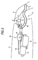
- Fig.2 is an enlarged view of a portion II in Fig.1
- Fig.3 is a side view of a drive unit
- Fig.4 is a side view of a state in which a motor of the drive unit is removed
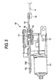
- Fig.5 is a plane view of the drive unit
- Fig.6 is a vertical sectional view enlarging the state of removing the motor of the drive unit taken along a VI-VI of Fig.3
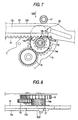
- Fig.7 is a side view enlarging an essential portion
- Fig.8 is a view viewing Fig.7 from an arrow mark VIII
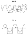
- Fig.9 is an enlarged side view of a IX portion of Fig.7.
- a left direction is defined as "front direction”
- a right direction is defined as "rear direction”.
- an opening portion (3) is formed by left and right rear pillars (not illustrated) and a rear edge of a roof panel (2), and the opening portion (3) can be opened and closed by a rear gate (5) constituting an opening and closing member pivotably attached thereto in an up and down direction via a pair of left and right hinge arms (4).
- a base end of the hinge arm (4) is pivotably attached to a hinge bracket (7) fixedly attached to an upper face of a rear roof rail (6) extended in a vehicle width direction along an upper edge portion of the opening portion (3) by a hinge shaft (8) directed in a left and right direction and the rear gate (5) is fixed with a rear end portion of a curved portion (4a) directed from the base end to the front direction in a skewed lower direction, constituting a shape of a circular arc centering of the hinge shaft (8) from a front end thereof and directed in the rear direction.
- the rear gate (5) is driven to open and close'over between a closed portion designated by a bold line in Fig.1 and an opened position designated by a two-dotted chain line by a drive unit (10) installed on a side of the vehicle body (1) between a lower face of the roof panel (2) and a roof trim (9) on an inner side of a vehicle compartment which is made to span on a lower side of the roof panel (2).
- the drive unit (10) includes a regularly and reversely rotatable motor (11), a gear box (12) and a rack (13).
- a longitudinal direction of a lower edge of the rack (13) there are continuously provided pluralities of gears of an opened position teeth portion (13a) (corresponding to "first teeth portion” of the invention) and a closed position teeth portion (13b) (corresponding to “second teeth portion” of the invention) which are capable of being meshed with a teeth portion (19a) of an output gear (19), mentioned later.
- a rear end portion of the rack (13) is connected to the curved portion (4a) of the hinge arm (4) by a connecting shaft (14) directed in the left and right direction.
- Two left and right side faces of the rack (13) are interposed between support plates (15) and (16) pivotably provided at an upper portion of the gear box (12) slidably in the front and rear direction.
- One side face of the rack (13) is provided with a guide groove (13c) in a recessed shape along a longitudinal (moving) direction of the rack (13).
- the guide groove (13c) is loosely fitted slidably with a projected portion (16a) projected to an inner side of the support plate (16).
- An upper edge (13d) of the rack (13) is guided in the front and rear direction by a guide member (17) pivotably attached between the support plates (15) and (16).
- the gear box (12) is pivotably attached with an intermediate gear (18) which is meshed with a pinion (not illustrated) rotated by the motor (11) via an electromagnetic clutch (not illustrated) provided at inside of the gear box (12) and the output gear (19) which is meshed with the intermediate gear (18) and the teeth portion (19a) of which can be meshed with the opened position teeth portion (13a) and the closed position teeth portion (13b) of the rack (13).
- a reference pitch line (P2) of the closed position teeth position (13b) is shifted from a reference pitch line (P1) of the opened position teeth portion (13a) in an outer direction (a direction of being remote from the teeth portion (19a) of the output gear (19)).
- Fig.10 shows a second embodiment of the invention.
- a tooth width (L1) of the closed position teeth portion (13b) in the rack (13) is made narrower than a tooth width (L2) of the opened position teeth portion (13a).
- the invention is not specified only to the rear gate but is applicable to other opening and closing member of a hood, a trunk lid or the like other than the rear gate.
Landscapes
- Power-Operated Mechanisms For Wings (AREA)
- Transmission Devices (AREA)
Abstract
Description
- The present application is based on Japanese Patent Application No. 2002-295610, the entire contents of which are incorparated herein by reference.
- The present invention relates to an opening and closing apparatus of a vehicular opening and closing member for connecting an opening and closing member pivotably attached to a vehicular body openably and closably and a rack meshed with an output gear pivotably supported by a side of the vehicle body and moved by rotating the output gear and moving to open and close the opening and closing member by moving the rack.
- According to an opening and closing apparatus of a vehicular opening and closing member of a related art, a driving unit having a regularly and reversely rotatable motor, a gear box provided with an output gear for reducing to output rotation of the motor and a rack meshed with an output gear and reciprocally moved in a front and gear direction is installed at a space between a lower face side of a roof panel and a roof trim on an inner side of a vehicle compartment, a rear end portion of the rack is connected to a side of an opening and closing member of a rear gate or the like pivotably attached openably and closably in an up and down direction by a hinge shaft directed in a left and right direction of a vehicle body and the opening and closing member is pivoted in an opening direction and a closing direction by reciprocally moving the rack in the front and rear direction by rotating the output gear (refer to, for example, Japanese Patent Publication No. JP-A-2001-280000).
- However, according to the above-described opening and closing apparatus of a vehicular opening and closing member of the related art, there is a concern of transmitting vibration of the opening and closing member disposed at a closed position in running the vehicle to the output pinion meshed with the rack via the rack and the vibration transmitted to the output pinion is transmitted to the gear box, the vehicle body and the like to emit large vibration sound.
- In view of the above-described problem provided to the related art, it is an object of the invention to provide an opening and closing apparatus of a vehicular opening and closing member preventing vibration from being transmitted to a side of an output gear when the opening and closing member is disposed at a closed position.
- According to the invention, the above-described program is solved as follows.
- (1) An opening and closing apparatus adapted for opening
and closing an opening and closing member pivotably attached
to a vehicle body, the opening and closing apparatus comprising:
- an output gear pivotably supported in a side of the vehicle body;
- a rack meshed with the output gear, the rack being moved by a rotation of the output gear and so as to open and close the opening and closing member by moving the rack,
- the rack including a first teeth portion and a second teeth portion, wherein the rack is meshed with the output gear at the first teeth portion when the opening and closing member is opened, and the rack is meshed with the output gear at the second teeth portion when the opening and closing member is closed, and
- a clearance between a tooth surface of a tooth in the second teeth portion and a mating tooth of the output gear is larger than a clearance between a tooth surface of a tooth of the first teeth portion and a mating tooth of the output gear.
- (2) In the above-described item (1), a reference pitch line of the second teeth portion may be shifted from a reference pitch line of the first teeth portion in a direction of being remote from the output gear.
- (3) In the above-described item (1), a tooth width of a tooth in the second teeth portion may be smaller than a tooth width of a tooth in the first teeth portion.
- (4) Another aspect of the invention provides:
- An opening and closing apparatus adapted for opening and
closing an opening and closing member pivotably attached to a
vehicle body, the opening and closing apparatus comprising:
- an output gear pivotably supported in a side of the vehicle body;
- a rack meshed with the output gear, the rack being moved by a rotation of the output gear and so as to open and close the opening and closing member by moving the rack,
- the rack including a first teeth portion and a second teeth portion, wherein the rack is meshed with the output gear at the first teeth portion when the opening and closing member is opened, and the rack is meshed with the output gear at the second teeth portion when the opening and closing member is closed, and
- a distance between opposing tooth surfaces in each adjacent teeth in the second teeth portion is made larger than a distance between opposing tooth surfaces in each adjacent teeth in the first teeth portion.
-
-
- Fig.1 is a side view of a rear portion of a vehicle body showing an outline of a first embodiment according to the invention;
- Fig.2 is an enlarged view of a portion indicated with II in Fig.1 of the first embodiment according to the invention;
- Fig. 3 is a side view of a drive unit of the first embodiment according to the invention;
- Fig.4 is a side view of a state in which a motor of the drive unit is removed of the first embodiment according to the invention;
- Fig.5 is a plane view of the drive unit of the first embodiment according to the invention;
- Fig.6 is a vertical sectional view enlarging a state of removing the motor of the drive unit along line VI-VI in Fig.3;
- Fig.7 is a side view enlarging an essential portion of the first embodiment according to the invention;
- Fig. 8 is a view shown in a direction indicated with a VIII arrow mark in Fig. 7;
- Fig.9 is a side view enlarging a IX portion of Fig.7; and
- Fig.10 is a side view enlarging an essential portion of a second embodiment according to the invention.
-
- An embodiment according to the invention will be explained in reference to Fig.1 through Fig.9 as follows.
- Fig.1 is a side view of a rear portion of a vehicle body having the embodiment, Fig.2 is an enlarged view of a portion II in Fig.1, Fig.3 is a side view of a drive unit, Fig.4 is a side view of a state in which a motor of the drive unit is removed, Fig.5 is a plane view of the drive unit, Fig.6 is a vertical sectional view enlarging the state of removing the motor of the drive unit taken along a VI-VI of Fig.3, Fig.7 is a side view enlarging an essential portion, Fig.8 is a view viewing Fig.7 from an arrow mark VIII, Fig.9 is an enlarged side view of a IX portion of Fig.7. Further, in the following explanation, in Fig.1 and Fig.2, a left direction is defined as "front direction" and a right direction is defined as "rear direction".
- At the rear portion of a vehicle body (1) an opening portion (3) is formed by left and right rear pillars (not illustrated) and a rear edge of a roof panel (2), and the opening portion (3) can be opened and closed by a rear gate (5) constituting an opening and closing member pivotably attached thereto in an up and down direction via a pair of left and right hinge arms (4).
- As shown by Fig.2, a base end of the hinge arm (4) is pivotably attached to a hinge bracket (7) fixedly attached to an upper face of a rear roof rail (6) extended in a vehicle width direction along an upper edge portion of the opening portion (3) by a hinge shaft (8) directed in a left and right direction and the rear gate (5) is fixed with a rear end portion of a curved portion (4a) directed from the base end to the front direction in a skewed lower direction, constituting a shape of a circular arc centering of the hinge shaft (8) from a front end thereof and directed in the rear direction.
- The rear gate (5) is driven to open and close'over between a closed portion designated by a bold line in Fig.1 and an opened position designated by a two-dotted chain line by a drive unit (10) installed on a side of the vehicle body (1) between a lower face of the roof panel (2) and a roof trim (9) on an inner side of a vehicle compartment which is made to span on a lower side of the roof panel (2).
- The drive unit (10) includes a regularly and reversely rotatable motor (11), a gear box (12) and a rack (13).
- In a longitudinal direction of a lower edge of the rack (13) there are continuously provided pluralities of gears of an opened position teeth portion (13a) (corresponding to "first teeth portion" of the invention) and a closed position teeth portion (13b) (corresponding to "second teeth portion" of the invention) which are capable of being meshed with a teeth portion (19a) of an output gear (19), mentioned later. A rear end portion of the rack (13) is connected to the curved portion (4a) of the hinge arm (4) by a connecting shaft (14) directed in the left and right direction.
- Two left and right side faces of the rack (13) are interposed between support plates (15) and (16) pivotably provided at an upper portion of the gear box (12) slidably in the front and rear direction. One side face of the rack (13) is provided with a guide groove (13c) in a recessed shape along a longitudinal (moving) direction of the rack (13). The guide groove (13c) is loosely fitted slidably with a projected portion (16a) projected to an inner side of the support plate (16). By engaging the guide groove (13c) and the projected portion (16a), an interval between the rack (13) and the output gear (19) in the up and down direction is maintained.
- An upper edge (13d) of the rack (13) is guided in the front and rear direction by a guide member (17) pivotably attached between the support plates (15) and (16).
- As mainly shown by Fig.6 and Fig.7, the gear box (12) is pivotably attached with an intermediate gear (18) which is meshed with a pinion (not illustrated) rotated by the motor (11) via an electromagnetic clutch (not illustrated) provided at inside of the gear box (12) and the output gear (19) which is meshed with the intermediate gear (18) and the teeth portion (19a) of which can be meshed with the opened position teeth portion (13a) and the closed position teeth portion (13b) of the rack (13).
- As shown by Fig.2 through Fig.5 and Fig.7 through Fig.9, when the rear gate (5) is disposed at a closed position, the rack (13) is disposed at a closed position corresponding to the closed position of the rear gate (5) and the closed position teeth portion (13b) is meshed with the teeth portion (19a) of the output gear (19). When an operation switch (not illustrated) is operated in the state, the electromagnetic clutch is brought into a connected state, the motor (11) is rotated and the output gear (19) is rotated in the clockwise direction in Fig.7 and Fig.9. Thereby, the rack (13) is moved in the right direction from the closed position to thereby move the rear gate (5) in an opening direction. When the rack (13) is moved from the closed position to an opened position corresponding to an opened position of the rear gate (5), the opened position teeth portion (13a) of the rack (13) is meshed with the teeth portion (19a) of the output gear (19).
- While the rear gate (5) is disposed at the opened position, when the motor (11) is rotated reversely by operating the operation switch, the rack (13) the opened position teeth portion (13a) of which is meshed with the teeth portion (19a) of the output gear (19) is moved in the left direction to thereby move to the closed position and in accordance therewith, the rear gate (5) is moved to the closed position.
- As shown by Fig.7 and Fig.9, a reference pitch line (P2) of the closed position teeth position (13b) is shifted from a reference pitch line (P1) of the opened position teeth portion (13a) in an outer direction (a direction of being remote from the teeth portion (19a) of the output gear (19)). Thereby, when the rack (13) is disposed at the closed position, the backlash (a clearance between tooth surfaces of teeth meshed with each other) between the closed position teeth portion (13b) and the teeth portion (19a) of the output gear (19) becomes larger than the backlash between the opened position teeth portion (13a) and the teeth portion (19a) which are meshed with each other when the rack (13) is disposed at the opened position.
- Therefore, when the rack (13) is disposed at the closed position, the contact between the tooth surfaces of the teeth of the closed position teeth portion (13b) and the teeth portion (19a) in all the time is excluded, vibration transmitted from the rear gate (5) disposed at the closed position in running the vehicle is shut off by the clearance between the closed position teeth portion (13b) and the teeth portion (19a) of the output gear (19) and the vibration of the rear gate (5) is not transmitted to the gear box (12), the vehicle body (1) and the like via the output gear (19) as in the related art (particularly, sound of bringing gears in mesh with each other emitted between the intermediate gear (18) and the output gear(19)).
- Fig.10 shows a second embodiment of the invention. According to the embodiment, a tooth width (L1) of the closed position teeth portion (13b) in the rack (13) is made narrower than a tooth width (L2) of the opened position teeth portion (13a). Thereby, when the rack (13) is disposed at the closed position, a clearance between tooth surfaces of teeth contiguous to each other of the closed position teeth portion (13b) and the teeth portion (19a) of the output gear (19) becomes larger than a clearance between surfaces of teeth contiguous to each other of the opened position teeth portion (13a) and the teeth portion (19a), thereby, transmission of vibration from the rear gate (5) can be shut off similar to the above-described embodiment.
- Further, the invention is not specified only to the rear gate but is applicable to other opening and closing member of a hood, a trunk lid or the like other than the rear gate.
- According to the invention, the following effect can be achieved.
- (a) According to the invention, by making the clearance between the surfaces of the teeth of the closed position teeth portion of the rack and the teeth portion of the output gear larger than the clearance between the surfaces of the teeth of the opened position teeth portion and the teeth portion of the output gear, vibration of the opening and closing member when the opening and closing member is disposed at the closed position is shut off by the clearance between the faces of the teeth of the closed position teeth portion and the teeth portion of the output gear and vibration can be prevented from being transmitted to a side of the output gear.
- (b) According to the invention, the vibration can firmly be prevented from being transmitted to a side of the output gear.
-
Claims (6)
- An opening and closing apparatus adapted for opening and closing an opening and closing member pivotably attached to a vehicle body, the opening and closing apparatus comprising:an output gear pivotably supported in a side of the vehicle body;a rack meshed with the output gear, the rack being moved by a rotation of the output gear and so as to open and close the opening and closing member by moving the rack,the rack including a first teeth portion and a second teeth portion, wherein the rack is meshed with the output gear at the first teeth portion when the opening and closing member is opened, and the rack is meshed with the output gear at the second teeth portion when the opening and closing member is closed, anda clearance between a tooth surface of a tooth in the second teeth portion and a mating tooth of the output gear is larger than a clearance between a tooth surface of a tooth of the first teeth portion and a mating tooth of the output gear.
- The opening and closing apparatus of a vehicular opening and closing member according to Claim 1, wherein a reference pitch line of the second teeth portion is shifted from a reference pitch line of the first teeth portion in a direction of being remote from the output gear.
- The opening and closing apparatus according to Claim 1, wherein a tooth width of a tooth in the second teeth portion is smaller than a tooth width of a tooth in the first teeth portion.
- An opening and closing apparatus adapted for opening and closing an opening and closing member pivotably attached to a vehicle body, the opening and closing apparatus comprising:an output gear pivotably supported in a side of the vehicle body;a rack meshed with the output gear, the rack being moved by a rotation of the output gear and so as to open and close the opening and closing member by moving the rack,the rack including a first teeth portion and a second teeth portion wherein the rack is meshed with the output gear at the first teeth portion when the opening and closing member is opened, and the rack is meshed with the output gear at the second teeth portion when the opening and closing member is closed, anda distance between opposing tooth surfaces in each adjacent teeth in the second teeth portion is larger than a distance between opposing tooth surfaces in each adjacent teeth in the first teeth portion.
- The opening and closing apparatus of a vehicular opening and closing member according to Claim 4, wherein a reference pitch line of the second teeth portion is shifted from a reference pitch line of the first teeth portion thereof in a direction of being remote from the output gear.
- The opening and closing apparatus of a vehicular opening and closing member according to Claim 4, wherein a tooth width of a tooth in the second teeth portion is smaller than a tooth width of a tooth in the first teeth portion.
Applications Claiming Priority (2)
| Application Number | Priority Date | Filing Date | Title |
|---|---|---|---|
| JP2002295610 | 2002-10-09 | ||
| JP2002295610A JP3761855B2 (en) | 2002-10-09 | 2002-10-09 | Opening and closing device for vehicle opening and closing body |
Publications (3)
| Publication Number | Publication Date |
|---|---|
| EP1408191A2 true EP1408191A2 (en) | 2004-04-14 |
| EP1408191A3 EP1408191A3 (en) | 2010-03-17 |
| EP1408191B1 EP1408191B1 (en) | 2012-12-12 |
Family
ID=32025527
Family Applications (1)
| Application Number | Title | Priority Date | Filing Date |
|---|---|---|---|
| EP03022848A Expired - Lifetime EP1408191B1 (en) | 2002-10-09 | 2003-10-08 | Opening and closing apparatus of vehicular opening and closing member |
Country Status (3)
| Country | Link |
|---|---|
| US (1) | US6776443B2 (en) |
| EP (1) | EP1408191B1 (en) |
| JP (1) | JP3761855B2 (en) |
Cited By (1)
| Publication number | Priority date | Publication date | Assignee | Title |
|---|---|---|---|---|
| DE102007030139B4 (en) * | 2006-07-24 | 2016-01-28 | BROSE SCHLIEßSYSTEME GMBH & CO. KG | Adjusting drive for moving a functional element in or on a motor vehicle body |
Families Citing this family (19)
| Publication number | Priority date | Publication date | Assignee | Title |
|---|---|---|---|---|
| JP3712236B2 (en) * | 2002-10-04 | 2005-11-02 | 本田技研工業株式会社 | Arrangement structure of door opening and closing device |
| JP4283600B2 (en) * | 2003-05-30 | 2009-06-24 | 株式会社大井製作所 | Opening and closing device for vehicle opening and closing body |
| US7144066B2 (en) * | 2003-07-30 | 2006-12-05 | Honda Motor Co., Ltd. | Power tailgate apparatus |
| CN1309614C (en) * | 2003-09-02 | 2007-04-11 | 本田技研工业株式会社 | Rear part structure of vehicle |
| JP3814270B2 (en) * | 2003-10-09 | 2006-08-23 | 本田技研工業株式会社 | Automatic switchgear for vehicles |
| DE10352167A1 (en) * | 2003-11-05 | 2005-06-09 | Siemens Ag | Actuator for actuating a tailgate of a motor vehicle |
| US8322074B2 (en) * | 2005-08-29 | 2012-12-04 | Mitsui Kinzoku Act Corporation | Power unit for power slide apparatus |
| JP4751160B2 (en) * | 2005-09-20 | 2011-08-17 | 三井金属アクト株式会社 | Opening and closing device for vehicle opening and closing body |
| US7566087B2 (en) * | 2006-08-18 | 2009-07-28 | Dura Global Technologies, Inc. | Power closure assembly |
| JP4588004B2 (en) * | 2006-09-12 | 2010-11-24 | トヨタ車体株式会社 | Vehicle power back door |
| US7500711B1 (en) * | 2007-08-24 | 2009-03-10 | Ford Global Technologies, Llc | Power door for a passenger vehicle |
| US20090120002A1 (en) * | 2007-09-07 | 2009-05-14 | Domholt Norman L | Door opening and closing device |
| DE102010029065B4 (en) * | 2010-05-18 | 2023-10-26 | Ford Global Technologies, Llc | Door edge protection device |
| DE102015215630A1 (en) | 2015-08-17 | 2017-02-23 | Brose Fahrzeugteile Gmbh & Co. Kommanditgesellschaft, Bamberg | Device for manual and / or electromotive adjustment or locking of a first vehicle part and a second vehicle part relative to each other |
| DE102015215631A1 (en) | 2015-08-17 | 2017-02-23 | Brose Fahrzeugteile Gmbh & Co. Kommanditgesellschaft, Bamberg | Device for manual and / or electromotive adjustment or locking of a first vehicle part and a second vehicle part relative to each other |
| DE102015215627A1 (en) | 2015-08-17 | 2017-02-23 | Brose Fahrzeugteile Gmbh & Co. Kommanditgesellschaft, Bamberg | Device for manual and / or electromotive adjustment or locking of a first vehicle part and a second vehicle part relative to each other |
| US10208523B1 (en) * | 2017-08-07 | 2019-02-19 | Honda Motor Co., Ltd. | Power tailgate mounting system for a vehicle |
| JP7183986B2 (en) | 2019-07-22 | 2022-12-06 | 三井金属アクト株式会社 | Vehicle side door operator |
| US11713609B2 (en) | 2019-11-01 | 2023-08-01 | Magna Closures Inc. | Powered door unit with improved mounting arrangement |
Family Cites Families (7)
| Publication number | Priority date | Publication date | Assignee | Title |
|---|---|---|---|---|
| US6142551A (en) * | 1998-12-17 | 2000-11-07 | Delphi Technologies, Inc. | Vehicle liftgate power operating system |
| US6367199B2 (en) * | 2000-02-22 | 2002-04-09 | Delphi Technologies, Inc. | Vehicle liftgate power operating system |
| JP3749074B2 (en) | 2000-03-28 | 2006-02-22 | 株式会社大井製作所 | Opening and closing device for vehicle opening and closing body |
| US6382706B2 (en) * | 2000-03-28 | 2002-05-07 | Ohi Seisakusho Co., Ltd. | Operating device for automotive pivotal door |
| US6676190B2 (en) * | 2000-04-27 | 2004-01-13 | Atoma International Corp. | Headliner mounted power liftgate drive mechanism |
| US6550839B2 (en) * | 2000-05-11 | 2003-04-22 | Delphi Technologies, Inc. | Vehicle pivoting closure power operating assembly |
| JP4006174B2 (en) * | 2000-09-20 | 2007-11-14 | 株式会社大井製作所 | Opening and closing device for opening and closing body in vehicle |
-
2002
- 2002-10-09 JP JP2002295610A patent/JP3761855B2/en not_active Expired - Fee Related
-
2003
- 2003-10-08 US US10/682,648 patent/US6776443B2/en not_active Expired - Lifetime
- 2003-10-08 EP EP03022848A patent/EP1408191B1/en not_active Expired - Lifetime
Non-Patent Citations (1)
| Title |
|---|
| None |
Cited By (1)
| Publication number | Priority date | Publication date | Assignee | Title |
|---|---|---|---|---|
| DE102007030139B4 (en) * | 2006-07-24 | 2016-01-28 | BROSE SCHLIEßSYSTEME GMBH & CO. KG | Adjusting drive for moving a functional element in or on a motor vehicle body |
Also Published As
| Publication number | Publication date |
|---|---|
| US6776443B2 (en) | 2004-08-17 |
| JP3761855B2 (en) | 2006-03-29 |
| EP1408191B1 (en) | 2012-12-12 |
| EP1408191A3 (en) | 2010-03-17 |
| US20040104594A1 (en) | 2004-06-03 |
| JP2004130873A (en) | 2004-04-30 |
Similar Documents
| Publication | Publication Date | Title |
|---|---|---|
| EP1408191B1 (en) | Opening and closing apparatus of vehicular opening and closing member | |
| US7137174B2 (en) | Activating mechanism for closures with four-link hinges | |
| JPS58214414A (en) | Safety device for sunroof on chassis | |
| JP3749708B2 (en) | Automatic switchgear for vehicles | |
| US20070063536A1 (en) | Opening and closing apparatus for opening and closing body of vehicle | |
| JPH0363377A (en) | Power window device | |
| JP3945762B2 (en) | Structure of door opening and closing device | |
| EP1803598B1 (en) | Door construction for vehicle, and manufacturing method for vehicular door | |
| JP4002457B2 (en) | Open / close device for vehicle rear gate | |
| JP2008126732A (en) | Drive device | |
| US7121043B2 (en) | Actuating device for open/close member of vehicle | |
| JP4776424B2 (en) | Opening and closing device for vehicle opening and closing body | |
| JP7399053B2 (en) | door closure device | |
| JP4105912B2 (en) | Mounting structure for a vehicle switchgear | |
| US20230322060A1 (en) | Sunroof structure of vehicle | |
| JP2007177587A (en) | Swing slide door | |
| JPH09142142A (en) | Vehicle side door device | |
| JP2001132329A (en) | Opening / closing device for vehicle opening / closing body | |
| CN117863839A (en) | Automobile front door upturning structure | |
| JP2001130261A (en) | Sunroof device for vehicles | |
| JPH01148617A (en) | Open/close panel for vehicle | |
| JP2004196230A (en) | Automatic switchgear for vehicles | |
| JP4487794B2 (en) | Automatic door opening and closing device for vehicle | |
| JPH08100443A (en) | Cab for construction machine | |
| KR100349564B1 (en) | Side glass drive system for vans |
Legal Events
| Date | Code | Title | Description |
|---|---|---|---|
| PUAI | Public reference made under article 153(3) epc to a published international application that has entered the european phase |
Free format text: ORIGINAL CODE: 0009012 |
|
| AK | Designated contracting states |
Kind code of ref document: A2 Designated state(s): AT BE BG CH CY CZ DE DK EE ES FI FR GB GR HU IE IT LI LU MC NL PT RO SE SI SK TR |
|
| AX | Request for extension of the european patent |
Extension state: AL LT LV MK |
|
| PUAL | Search report despatched |
Free format text: ORIGINAL CODE: 0009013 |
|
| AK | Designated contracting states |
Kind code of ref document: A3 Designated state(s): AT BE BG CH CY CZ DE DK EE ES FI FR GB GR HU IE IT LI LU MC NL PT RO SE SI SK TR |
|
| AX | Request for extension of the european patent |
Extension state: AL LT LV MK |
|
| 17P | Request for examination filed |
Effective date: 20100810 |
|
| AKX | Designation fees paid |
Designated state(s): AT BE BG CH CY CZ DE DK EE ES FI FR GB GR HU IE IT LI LU MC NL PT RO SE SI SK TR |
|
| RAP1 | Party data changed (applicant data changed or rights of an application transferred) |
Owner name: MITSUI KINZOKU ACT CORPORATION Owner name: HONDA MOTOR CO., LTD. |
|
| 17Q | First examination report despatched |
Effective date: 20110615 |
|
| GRAP | Despatch of communication of intention to grant a patent |
Free format text: ORIGINAL CODE: EPIDOSNIGR1 |
|
| GRAS | Grant fee paid |
Free format text: ORIGINAL CODE: EPIDOSNIGR3 |
|
| GRAA | (expected) grant |
Free format text: ORIGINAL CODE: 0009210 |
|
| AK | Designated contracting states |
Kind code of ref document: B1 Designated state(s): AT BE BG CH CY CZ DE DK EE ES FI FR GB GR HU IE IT LI LU MC NL PT RO SE SI SK TR |
|
| REG | Reference to a national code |
Ref country code: GB Ref legal event code: FG4D |
|
| REG | Reference to a national code |
Ref country code: CH Ref legal event code: EP |
|
| REG | Reference to a national code |
Ref country code: AT Ref legal event code: REF Ref document number: 588419 Country of ref document: AT Kind code of ref document: T Effective date: 20121215 |
|
| REG | Reference to a national code |
Ref country code: IE Ref legal event code: FG4D |
|
| REG | Reference to a national code |
Ref country code: DE Ref legal event code: R096 Ref document number: 60342815 Country of ref document: DE Effective date: 20130207 |
|
| PG25 | Lapsed in a contracting state [announced via postgrant information from national office to epo] |
Ref country code: ES Free format text: LAPSE BECAUSE OF FAILURE TO SUBMIT A TRANSLATION OF THE DESCRIPTION OR TO PAY THE FEE WITHIN THE PRESCRIBED TIME-LIMIT Effective date: 20130323 Ref country code: SE Free format text: LAPSE BECAUSE OF FAILURE TO SUBMIT A TRANSLATION OF THE DESCRIPTION OR TO PAY THE FEE WITHIN THE PRESCRIBED TIME-LIMIT Effective date: 20121212 Ref country code: FI Free format text: LAPSE BECAUSE OF FAILURE TO SUBMIT A TRANSLATION OF THE DESCRIPTION OR TO PAY THE FEE WITHIN THE PRESCRIBED TIME-LIMIT Effective date: 20121212 |
|
| REG | Reference to a national code |
Ref country code: NL Ref legal event code: VDEP Effective date: 20121212 |
|
| REG | Reference to a national code |
Ref country code: AT Ref legal event code: MK05 Ref document number: 588419 Country of ref document: AT Kind code of ref document: T Effective date: 20121212 |
|
| PG25 | Lapsed in a contracting state [announced via postgrant information from national office to epo] |
Ref country code: SI Free format text: LAPSE BECAUSE OF FAILURE TO SUBMIT A TRANSLATION OF THE DESCRIPTION OR TO PAY THE FEE WITHIN THE PRESCRIBED TIME-LIMIT Effective date: 20121212 Ref country code: GR Free format text: LAPSE BECAUSE OF FAILURE TO SUBMIT A TRANSLATION OF THE DESCRIPTION OR TO PAY THE FEE WITHIN THE PRESCRIBED TIME-LIMIT Effective date: 20130313 |
|
| PG25 | Lapsed in a contracting state [announced via postgrant information from national office to epo] |
Ref country code: CY Free format text: LAPSE BECAUSE OF FAILURE TO SUBMIT A TRANSLATION OF THE DESCRIPTION OR TO PAY THE FEE WITHIN THE PRESCRIBED TIME-LIMIT Effective date: 20121212 Ref country code: BG Free format text: LAPSE BECAUSE OF FAILURE TO SUBMIT A TRANSLATION OF THE DESCRIPTION OR TO PAY THE FEE WITHIN THE PRESCRIBED TIME-LIMIT Effective date: 20130312 Ref country code: CZ Free format text: LAPSE BECAUSE OF FAILURE TO SUBMIT A TRANSLATION OF THE DESCRIPTION OR TO PAY THE FEE WITHIN THE PRESCRIBED TIME-LIMIT Effective date: 20121212 Ref country code: AT Free format text: LAPSE BECAUSE OF FAILURE TO SUBMIT A TRANSLATION OF THE DESCRIPTION OR TO PAY THE FEE WITHIN THE PRESCRIBED TIME-LIMIT Effective date: 20121212 Ref country code: SK Free format text: LAPSE BECAUSE OF FAILURE TO SUBMIT A TRANSLATION OF THE DESCRIPTION OR TO PAY THE FEE WITHIN THE PRESCRIBED TIME-LIMIT Effective date: 20121212 Ref country code: EE Free format text: LAPSE BECAUSE OF FAILURE TO SUBMIT A TRANSLATION OF THE DESCRIPTION OR TO PAY THE FEE WITHIN THE PRESCRIBED TIME-LIMIT Effective date: 20121212 Ref country code: BE Free format text: LAPSE BECAUSE OF FAILURE TO SUBMIT A TRANSLATION OF THE DESCRIPTION OR TO PAY THE FEE WITHIN THE PRESCRIBED TIME-LIMIT Effective date: 20121212 |
|
| PG25 | Lapsed in a contracting state [announced via postgrant information from national office to epo] |
Ref country code: PT Free format text: LAPSE BECAUSE OF FAILURE TO SUBMIT A TRANSLATION OF THE DESCRIPTION OR TO PAY THE FEE WITHIN THE PRESCRIBED TIME-LIMIT Effective date: 20130412 Ref country code: NL Free format text: LAPSE BECAUSE OF FAILURE TO SUBMIT A TRANSLATION OF THE DESCRIPTION OR TO PAY THE FEE WITHIN THE PRESCRIBED TIME-LIMIT Effective date: 20121212 Ref country code: RO Free format text: LAPSE BECAUSE OF FAILURE TO SUBMIT A TRANSLATION OF THE DESCRIPTION OR TO PAY THE FEE WITHIN THE PRESCRIBED TIME-LIMIT Effective date: 20121212 |
|
| PLBE | No opposition filed within time limit |
Free format text: ORIGINAL CODE: 0009261 |
|
| STAA | Information on the status of an ep patent application or granted ep patent |
Free format text: STATUS: NO OPPOSITION FILED WITHIN TIME LIMIT |
|
| PG25 | Lapsed in a contracting state [announced via postgrant information from national office to epo] |
Ref country code: DK Free format text: LAPSE BECAUSE OF FAILURE TO SUBMIT A TRANSLATION OF THE DESCRIPTION OR TO PAY THE FEE WITHIN THE PRESCRIBED TIME-LIMIT Effective date: 20121212 |
|
| 26N | No opposition filed |
Effective date: 20130913 |
|
| PG25 | Lapsed in a contracting state [announced via postgrant information from national office to epo] |
Ref country code: IT Free format text: LAPSE BECAUSE OF FAILURE TO SUBMIT A TRANSLATION OF THE DESCRIPTION OR TO PAY THE FEE WITHIN THE PRESCRIBED TIME-LIMIT Effective date: 20121212 |
|
| REG | Reference to a national code |
Ref country code: DE Ref legal event code: R097 Ref document number: 60342815 Country of ref document: DE Effective date: 20130913 |
|
| PG25 | Lapsed in a contracting state [announced via postgrant information from national office to epo] |
Ref country code: MC Free format text: LAPSE BECAUSE OF FAILURE TO SUBMIT A TRANSLATION OF THE DESCRIPTION OR TO PAY THE FEE WITHIN THE PRESCRIBED TIME-LIMIT Effective date: 20121212 |
|
| REG | Reference to a national code |
Ref country code: CH Ref legal event code: PL |
|
| REG | Reference to a national code |
Ref country code: IE Ref legal event code: MM4A |
|
| PG25 | Lapsed in a contracting state [announced via postgrant information from national office to epo] |
Ref country code: LI Free format text: LAPSE BECAUSE OF NON-PAYMENT OF DUE FEES Effective date: 20131031 Ref country code: CH Free format text: LAPSE BECAUSE OF NON-PAYMENT OF DUE FEES Effective date: 20131031 |
|
| PG25 | Lapsed in a contracting state [announced via postgrant information from national office to epo] |
Ref country code: IE Free format text: LAPSE BECAUSE OF NON-PAYMENT OF DUE FEES Effective date: 20131008 |
|
| PG25 | Lapsed in a contracting state [announced via postgrant information from national office to epo] |
Ref country code: TR Free format text: LAPSE BECAUSE OF FAILURE TO SUBMIT A TRANSLATION OF THE DESCRIPTION OR TO PAY THE FEE WITHIN THE PRESCRIBED TIME-LIMIT Effective date: 20121212 |
|
| PG25 | Lapsed in a contracting state [announced via postgrant information from national office to epo] |
Ref country code: HU Free format text: LAPSE BECAUSE OF FAILURE TO SUBMIT A TRANSLATION OF THE DESCRIPTION OR TO PAY THE FEE WITHIN THE PRESCRIBED TIME-LIMIT; INVALID AB INITIO Effective date: 20031008 Ref country code: LU Free format text: LAPSE BECAUSE OF NON-PAYMENT OF DUE FEES Effective date: 20131008 |
|
| REG | Reference to a national code |
Ref country code: FR Ref legal event code: PLFP Year of fee payment: 13 |
|
| PGFP | Annual fee paid to national office [announced via postgrant information from national office to epo] |
Ref country code: GB Payment date: 20151009 Year of fee payment: 13 |
|
| PGFP | Annual fee paid to national office [announced via postgrant information from national office to epo] |
Ref country code: FR Payment date: 20151026 Year of fee payment: 13 |
|
| GBPC | Gb: european patent ceased through non-payment of renewal fee |
Effective date: 20161008 |
|
| REG | Reference to a national code |
Ref country code: FR Ref legal event code: ST Effective date: 20170630 |
|
| PG25 | Lapsed in a contracting state [announced via postgrant information from national office to epo] |
Ref country code: FR Free format text: LAPSE BECAUSE OF NON-PAYMENT OF DUE FEES Effective date: 20161102 Ref country code: GB Free format text: LAPSE BECAUSE OF NON-PAYMENT OF DUE FEES Effective date: 20161008 |
|
| PGFP | Annual fee paid to national office [announced via postgrant information from national office to epo] |
Ref country code: DE Payment date: 20170921 Year of fee payment: 15 |
|
| REG | Reference to a national code |
Ref country code: DE Ref legal event code: R119 Ref document number: 60342815 Country of ref document: DE |
|
| PG25 | Lapsed in a contracting state [announced via postgrant information from national office to epo] |
Ref country code: DE Free format text: LAPSE BECAUSE OF NON-PAYMENT OF DUE FEES Effective date: 20190501 |