EP1408009A1 - Reactor with two gas separators and method for the anaerobic treatment of liquids - Google Patents
Reactor with two gas separators and method for the anaerobic treatment of liquids Download PDFInfo
- Publication number
- EP1408009A1 EP1408009A1 EP02022760A EP02022760A EP1408009A1 EP 1408009 A1 EP1408009 A1 EP 1408009A1 EP 02022760 A EP02022760 A EP 02022760A EP 02022760 A EP02022760 A EP 02022760A EP 1408009 A1 EP1408009 A1 EP 1408009A1
- Authority
- EP
- European Patent Office
- Prior art keywords
- gas
- reactor
- riser pipe
- gas separator
- reactor according
- Prior art date
- Legal status (The legal status is an assumption and is not a legal conclusion. Google has not performed a legal analysis and makes no representation as to the accuracy of the status listed.)
- Granted
Links
- QWHNJUXXYKPLQM-UHFFFAOYSA-N CC1(C)CCCC1 Chemical compound CC1(C)CCCC1 QWHNJUXXYKPLQM-UHFFFAOYSA-N 0.000 description 1
Images

Classifications
-
- C—CHEMISTRY; METALLURGY
- C12—BIOCHEMISTRY; BEER; SPIRITS; WINE; VINEGAR; MICROBIOLOGY; ENZYMOLOGY; MUTATION OR GENETIC ENGINEERING
- C12M—APPARATUS FOR ENZYMOLOGY OR MICROBIOLOGY; APPARATUS FOR CULTURING MICROORGANISMS FOR PRODUCING BIOMASS, FOR GROWING CELLS OR FOR OBTAINING FERMENTATION OR METABOLIC PRODUCTS, i.e. BIOREACTORS OR FERMENTERS
- C12M27/00—Means for mixing, agitating or circulating fluids in the vessel
- C12M27/18—Flow directing inserts
- C12M27/24—Draft tube
-
- C—CHEMISTRY; METALLURGY
- C02—TREATMENT OF WATER, WASTE WATER, SEWAGE, OR SLUDGE
- C02F—TREATMENT OF WATER, WASTE WATER, SEWAGE, OR SLUDGE
- C02F3/00—Biological treatment of water, waste water, or sewage
- C02F3/28—Anaerobic digestion processes
- C02F3/2846—Anaerobic digestion processes using upflow anaerobic sludge blanket [UASB] reactors
-
- C—CHEMISTRY; METALLURGY
- C12—BIOCHEMISTRY; BEER; SPIRITS; WINE; VINEGAR; MICROBIOLOGY; ENZYMOLOGY; MUTATION OR GENETIC ENGINEERING
- C12M—APPARATUS FOR ENZYMOLOGY OR MICROBIOLOGY; APPARATUS FOR CULTURING MICROORGANISMS FOR PRODUCING BIOMASS, FOR GROWING CELLS OR FOR OBTAINING FERMENTATION OR METABOLIC PRODUCTS, i.e. BIOREACTORS OR FERMENTERS
- C12M21/00—Bioreactors or fermenters specially adapted for specific uses
- C12M21/04—Bioreactors or fermenters specially adapted for specific uses for producing gas, e.g. biogas
-
- C—CHEMISTRY; METALLURGY
- C12—BIOCHEMISTRY; BEER; SPIRITS; WINE; VINEGAR; MICROBIOLOGY; ENZYMOLOGY; MUTATION OR GENETIC ENGINEERING
- C12M—APPARATUS FOR ENZYMOLOGY OR MICROBIOLOGY; APPARATUS FOR CULTURING MICROORGANISMS FOR PRODUCING BIOMASS, FOR GROWING CELLS OR FOR OBTAINING FERMENTATION OR METABOLIC PRODUCTS, i.e. BIOREACTORS OR FERMENTERS
- C12M23/00—Constructional details, e.g. recesses, hinges
- C12M23/36—Means for collection or storage of gas; Gas holders
-
- C—CHEMISTRY; METALLURGY
- C12—BIOCHEMISTRY; BEER; SPIRITS; WINE; VINEGAR; MICROBIOLOGY; ENZYMOLOGY; MUTATION OR GENETIC ENGINEERING
- C12M—APPARATUS FOR ENZYMOLOGY OR MICROBIOLOGY; APPARATUS FOR CULTURING MICROORGANISMS FOR PRODUCING BIOMASS, FOR GROWING CELLS OR FOR OBTAINING FERMENTATION OR METABOLIC PRODUCTS, i.e. BIOREACTORS OR FERMENTERS
- C12M27/00—Means for mixing, agitating or circulating fluids in the vessel
- C12M27/18—Flow directing inserts
- C12M27/20—Baffles; Ribs; Ribbons; Auger vanes
-
- Y—GENERAL TAGGING OF NEW TECHNOLOGICAL DEVELOPMENTS; GENERAL TAGGING OF CROSS-SECTIONAL TECHNOLOGIES SPANNING OVER SEVERAL SECTIONS OF THE IPC; TECHNICAL SUBJECTS COVERED BY FORMER USPC CROSS-REFERENCE ART COLLECTIONS [XRACs] AND DIGESTS
- Y02—TECHNOLOGIES OR APPLICATIONS FOR MITIGATION OR ADAPTATION AGAINST CLIMATE CHANGE
- Y02E—REDUCTION OF GREENHOUSE GAS [GHG] EMISSIONS, RELATED TO ENERGY GENERATION, TRANSMISSION OR DISTRIBUTION
- Y02E50/00—Technologies for the production of fuel of non-fossil origin
- Y02E50/30—Fuel from waste, e.g. synthetic alcohol or diesel
Definitions
- the invention relates to a reactor and a corresponding method for anaerobic Treatment of liquids, especially waste water or aqueous process solutions, through anaerobic biological conversion of organic contaminants using granulated, flocculent or biomass fixed on easily fluidizable carrier materials, whereby the reactor has a first gas separator and a second gas separator in one Has a distance above it.
- Anaerobic cleaning of organically contaminated wastewater is advantageous in sludge bed reactors operated according to the UASB principle. Reactors after this Principle, e.g. in EP 0 244 029 B1 and EP 0 808 805 A1. The invention described here also uses the UASB principle.
- the cleaning process takes place in a three-phase system, consisting of the liquid that represents the wastewater to be treated, the solid - the fluffy or granulated biomass present in the sludge bed or the easily fluidizable biomass carrier - and the gas phase, which mainly consists of methane CH 4 , Carbon dioxide CO 2 and trace gases.
- the biomass of a UASB reactor is ideally in the form of a mixture (Sludge) that is made up of spherical agglomerates (sludge pellets) and fine sludge composed, the sludge pellets ideally diameter of less than 1 to 5 mm and have a higher density than water, resulting in a Mud bed.
- the biomass can also be applied to carrier media so that the following explanations about sludge or sludge pellets also refer to these carrier media covered with biomass.
- UASB reactors contain three-phase separators that allow the three phases Biogas, purified wastewater and biomass are separated. These three-phase separators are usually located above the mud bed one or more hoods for collecting and conveying the biogas and on the water surface drainage channels for the discharge of the cleaned wastewater. This Constructions allow the sedimentation of the biomass after gas separation.
- the UASB reactor constructed in this way is large in volume and allows only a small amount Conversion rates.
- An object of the invention is to modify the reactor structure so that high volume-specific sales rates and thus a more efficient utilization of the reactor volume can be achieved.
- the biomass forms a sludge bed in the bottom area the wastewater to be treated is fed.
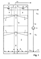
- the first gas separator is in the lower one Area of the reactor arranged, so in the sludge bed of the reactor. In the mud bed Much of the biochemical conversion of the organic material takes place. The A large part of the resulting biogas is captured by the first gas separator and directed into a central riser. The rest of the gas flows through the area above the sludge bed and is held in a second gas separator, which is over the mud bed and is also derived into the riser pipe. A little rest escapes on the water surface into the gas collection space above. Above The second gas separator has a sedimentation zone for the biomass.
- a part is separated by a gas separator arranged in the sludge bed of the reactor of the biogas is already removed from the system in the sludge bed, which makes it too high Empty gas pipe speeds can be avoided.
- the diameter of the riser pipe is dimensioned so that 5 to 25% of the cross-sectional area of the reactor is filled by the riser pipe. This will usually result in a Gas jack effect (mammoth pump effect) avoided.
- the gas separator elements are arranged radially to the riser pipe, because then the gas collected on the concave bottom of the gas separator element can flow along the gas separator element to the riser pipe. This can be done are supported that the gas separator elements are arranged obliquely to the horizontal are, that is, the end of the reactor wall is lower than that of the riser.
- the configuration according to which the riser pipe for each is also advantageous and simple Gas separator element has at least one gas transfer opening, of which the gas collected by the gas separator element can flow directly into the riser pipe. There are therefore no other devices, such as a drain pipe for each one Gas separator element is required to discharge the gas. This function is used alone fulfilled by the gas separator element and the gas transfer opening.
- any biomass carried into the riser can easily be in the riser themselves are conveyed downward by having openings through which Biomass from the riser pipe can sink into the reactor space.
- the carried Floating sludge is separated by a baffle at the top of the riser.
- the trigger devices located outside the baffle are opened this way kept free from swimming mud.
- the first gas separator is located in the lower half of the reactor 1, which consists of a layer of gas separator elements that collect enable the biogas formed and it towards the central riser 6 in which the biogas rises.
- a second gas separator 3 which also consists of a Location of gas separator elements.
- connection between the gas separator elements of the two gas separators 1, 3 and the straight, central riser pipe 6 form gas inlet openings 7, which are the transition enable the biogas into the riser pipe 6, so that the biogas into the gas collecting space 13 can rise. From there, the biogas is drawn off, as indicated by line 15.
- the second gas separator 3 on the reactor head By gas pre-separation in the sludge bed 2 through the first gas separator 1 and the sedimentation of the biomass, by the second gas separator 3 on the reactor head, preferably sludge pellets, in the sedimentation chamber 4 above the second gas separator 3 reached.
- Clear water drainage devices are located on the water surface 8, such as gutters.
- the central riser pipe 6 For the separation or retention of floating sludge of the extraction devices is the central riser pipe 6 with a baffle 9 surrounded.
- the baffle 9 is designed here as a tube that is concentric with the riser 6 is arranged outside the riser pipe, and extends from the second gas separator 3 to over the upper end of the riser pipe 6, which ends below the water surface 12 and further beyond the water surface into the gas collecting space 13.
- the riser pipe has openings 20 in the lower region near the bottom through which Biomass from the riser 6 can sink back into the reactor space.
- the riser pipe 6 extends to the bottom of the reactor, with the lower pipe end opposite the reactor is complete.
- the upper pipe end of the riser pipe is open.
- a recirculation from the outlet may be necessary to set defined inlet concentrations of the reactor via a pump 14 and a recirculation line 10 into the feed pipe 11 required.
- Fig. 2 is a cross section according to a horizontal sectional area between the second gas separator 3 and water surface 12 according to FIG. 1 and shows the arrangement of the gas separator elements 16 in the reactor, only three gas separator elements 16 being shown are.
- each gas separator 1, 3 is made of one layer of gas separator elements 16 formed, which overlap each other in partial areas and essentially the Cover the entire reactor cross section outside the riser pipe 6. Every gas separator element 16 covers a sector-shaped cross-sectional area which in this case is circular Reactor cross section and extends from the wall of the riser 6 to the reactor wall 17th
- Fig. 3 shows a gas separator element 16 in cross section looking towards the riser 6.
- the cross section of the gas separator element 16 is angular and asymmetrical formed by extending one leg 18 of the hood-shaped gas separator element is formed as the other leg 19.
- the cross section of the gas separator elements 16 increases in the radial direction in proportion to the distance from the riser pipe 6, so that - As shown in Fig. 2 - the reactor cross-section essentially by a layer of Gas separator elements 16 can be covered.
- the sludge pellets sedimented in the sedimentation room 4 slide along the tops of gas separator elements 16 and sink between the gas separator elements 16 down back into the mud bed.
Landscapes
- Life Sciences & Earth Sciences (AREA)
- Health & Medical Sciences (AREA)
- Engineering & Computer Science (AREA)
- Chemical & Material Sciences (AREA)
- Organic Chemistry (AREA)
- Zoology (AREA)
- Wood Science & Technology (AREA)
- Bioinformatics & Cheminformatics (AREA)
- Microbiology (AREA)
- Genetics & Genomics (AREA)
- Biochemistry (AREA)
- General Engineering & Computer Science (AREA)
- General Health & Medical Sciences (AREA)
- Sustainable Development (AREA)
- Biomedical Technology (AREA)
- Biotechnology (AREA)
- Molecular Biology (AREA)
- Water Supply & Treatment (AREA)
- Oil, Petroleum & Natural Gas (AREA)
- General Chemical & Material Sciences (AREA)
- Environmental & Geological Engineering (AREA)
- Hydrology & Water Resources (AREA)
- Biodiversity & Conservation Biology (AREA)
- Clinical Laboratory Science (AREA)
- Purification Treatments By Anaerobic Or Anaerobic And Aerobic Bacteria Or Animals (AREA)
Abstract
Description
Die Erfindung betrifft einen Reaktor sowie ein entsprechendes Verfahren zur anaeroben Behandlung von Flüssigkeiten, inbesondere von Abwasser oder wässrigen Prozesslösungen, durch anaerobe biologische Umsetzung organischer Verunreinigungen mittels granulierter, flockiger oder auf leicht fluidisierbaren Trägermaterialien fixierter Biomasse, wobei der Reaktor einen ersten Gasabscheider und einen zweiten Gasabscheider in einem Abstand darüber aufweist.The invention relates to a reactor and a corresponding method for anaerobic Treatment of liquids, especially waste water or aqueous process solutions, through anaerobic biological conversion of organic contaminants using granulated, flocculent or biomass fixed on easily fluidizable carrier materials, whereby the reactor has a first gas separator and a second gas separator in one Has a distance above it.
Die anaerobe Reinigung organisch belasteter Abwässer wird vorteilhaft in Schlammbettreaktoren betrieben, die nach dem UASB-Prinzip arbeiten. Reaktoren, die nach diesem Prinzip arbeiten, werden z.B. in der EP 0 244 029 B1 und EP 0 808 805 A1 beschrieben. Auch die hier beschriebene Erfindung nutzt das UASB-Prinzip.Anaerobic cleaning of organically contaminated wastewater is advantageous in sludge bed reactors operated according to the UASB principle. Reactors after this Principle, e.g. in EP 0 244 029 B1 and EP 0 808 805 A1. The invention described here also uses the UASB principle.
Der Vorgang der Reinigung läuft in einem Dreiphasensystem ab, bestehend aus der Flüssigkeit, welche das zu behandelnde Abwasser darstellt, aus dem Feststoff - der im Schlammbett vorliegenden flockigen oder granulierten Biomasse oder dem leicht fluidisierbaren Biomasseträger - sowie der Gasphase, die vorwiegend aus Methan CH4, Kohlendioxid CO2 und Spurengasen besteht.The cleaning process takes place in a three-phase system, consisting of the liquid that represents the wastewater to be treated, the solid - the fluffy or granulated biomass present in the sludge bed or the easily fluidizable biomass carrier - and the gas phase, which mainly consists of methane CH 4 , Carbon dioxide CO 2 and trace gases.
Die Biomasse eines UASB-Reaktors liegt idealerweise in Form eines Gemisches (Schlamm) vor, dass sich aus kugelförmigen Agglomeraten (Schlammpellets) und Feinschlamm zusammensetzt, wobei die Schlammpellets idealer Weise Durchmesser von unter 1 bis 5 mm und eine höhere Dichte als Wasser aufweisen, wodurch sich ein Schlammbett ausbildet. Die Biomasse kann aber auch auf Trägermedien aufgebracht werden, sodass sich die folgenden Ausführungen zu Schlamm bzw. Schlammpellets auch auf diese mit Biomasse bewachsenen Trägermedien beziehen.The biomass of a UASB reactor is ideally in the form of a mixture (Sludge) that is made up of spherical agglomerates (sludge pellets) and fine sludge composed, the sludge pellets ideally diameter of less than 1 to 5 mm and have a higher density than water, resulting in a Mud bed. The biomass can also be applied to carrier media so that the following explanations about sludge or sludge pellets also refer to these carrier media covered with biomass.
Im Schlammbett erfolgt ein Großteil der Umsetzung des organischen Materials. Durch die im Schlammbett erfolgende Biogaserzeugung kommt es zu einer Blasenbildung. Die aufsteigenden Blasen und der aufwärts gerichtete Flüssigkeitsstrom fluidisieren das Schlammbett.Much of the conversion of the organic material takes place in the sludge bed. Through the Bubble formation occurs in the sludge bed. The ascending Bubbles and the upward fluid flow fluidize that Sludge bed.
UASB-Reaktoren enthalten Dreiphasen-Trennvorrichtungen, mit denen die drei Phasen Biogas, gereinigtes Abwasser und Biomasse voneinander getrennt werden. Diese Dreiphasen-Trennvorrichtungen sind in der Regel über dem Schlammbett angeordnet, enthalten eine oder mehrere Hauben zum Auffangen und Fortleiten des Biogases sowie an der Wasseroberfläche Ablaufrinnen für die Fortleitung des gereinigten Abwassers. Diese Konstruktionen erlauben nach Gasabtrennung die Sedimentation der Biomasse. UASB reactors contain three-phase separators that allow the three phases Biogas, purified wastewater and biomass are separated. These three-phase separators are usually located above the mud bed one or more hoods for collecting and conveying the biogas and on the water surface drainage channels for the discharge of the cleaned wastewater. This Constructions allow the sedimentation of the biomass after gas separation.
Der auf diese Weise konstruierte UASB-Reaktor ist großvolumig und erlaubt nur geringe Umsatzraten.The UASB reactor constructed in this way is large in volume and allows only a small amount Conversion rates.
Eine Aufgabe der Erfindung ist es nun, den Reaktoraufbau so zu modifizieren, dass sehr hohe volumenspezifische Umsatzraten und damit eine effizientere Ausnutzung des Reaktorvolumens erzielt werden können.An object of the invention is to modify the reactor structure so that high volume-specific sales rates and thus a more efficient utilization of the reactor volume can be achieved.
Diese Aufgaben werden erfindungsgemäß durch einen Reaktor nach Anspruch 1 bzw.
durch ein Verfahren nach Anspruch 11 gelöst. Die Ansprüche 2 bis 10 betreffen bevorzugte
Ausführungen der Erfindung.According to the invention, these objects are achieved by a reactor according to
Die Biomasse bildet im nicht fluidisiertem Zustand ein Schlammbett, in dessen Bodenbereich das zu behandelnde Abwasser zugeführt wird. Der erste Gasabscheider ist im unteren Bereich des Reaktors angeordnet, also im Schlammbett des Reaktors. Im Schlammbett erfolgt ein Großteil der biochemischen Umsetzung des organischen Materials. Das dabei entstehende Biogas wird zu einem erheblichen Teil vom ersten Gasabscheider gefasst und in ein zentrales Steigrohr geleitet. Das restliche Gas durchströmt den Bereich über dem Schlammbett und wird in einem zweiten Gasabscheider gefasst, der sich über dem Schlammbett befindet und ebenfalls in das Steigrohr abgeleitet. Ein geringer Rest entweicht an der Wasseroberfläche in den darüberliegenden Gassammelraum. Oberhalb des zweiten Gasabscheiders befindet sich eine Sedimentationszone für die Biomasse.In the non-fluidized state, the biomass forms a sludge bed in the bottom area the wastewater to be treated is fed. The first gas separator is in the lower one Area of the reactor arranged, so in the sludge bed of the reactor. In the mud bed Much of the biochemical conversion of the organic material takes place. The A large part of the resulting biogas is captured by the first gas separator and directed into a central riser. The rest of the gas flows through the area above the sludge bed and is held in a second gas separator, which is over the mud bed and is also derived into the riser pipe. A little rest escapes on the water surface into the gas collection space above. Above The second gas separator has a sedimentation zone for the biomass.
Durch einen im Schlammbett des Reaktors angeordneten Gasabscheider wird ein Teil des Biogases schon im Schlammbett aus dem System entnommen, wodurch zu hohe Gasleerrohrgeschwindigkeiten vermieden werden.A part is separated by a gas separator arranged in the sludge bed of the reactor of the biogas is already removed from the system in the sludge bed, which makes it too high Empty gas pipe speeds can be avoided.
Der Durchmesser des Steigrohres ist dabei so bemessen, dass 5 bis 25% der Querschnittsfläche des Reaktors vom Steigrohr ausgefüllt wird. Dadurch wird in der Regel ein Gashebereffekt (Mammutpumpeneffekt) vermieden.The diameter of the riser pipe is dimensioned so that 5 to 25% of the cross-sectional area of the reactor is filled by the riser pipe. This will usually result in a Gas jack effect (mammoth pump effect) avoided.
Indem das Steigrohr etwa in einer zentralen Achse des Reaktors, insbesondere in seiner zentralen Längsachse, angeordnet ist, können im Reaktor zu dieser zentralen Achse symmetrische Strömungsbedingungen hergestellt werden.By having the riser pipe approximately in a central axis of the reactor, in particular in its central longitudinal axis, is arranged in the reactor to this central axis symmetrical flow conditions can be established.
Es ist konstruktiv einfach, wenn ein Gasabscheider aus gleichartigen Gasabscheiderelementen aufgebaut ist. Dabei ist es ausreichend, wenn die Gasabscheider jeweils aus einer Lage Gasabscheiderelementen gebildet werden.It is structurally simple if a gas separator consists of similar gas separator elements is constructed. It is sufficient if the gas separator consists of one Location gas separator elements are formed.
Vorteilhaft ist, wenn die Gasabscheiderelemente radial zum Steigrohr angeordnet sind, weil dann das auf der konkaven Unterseite des Gasabscheiderelements gesammelte Gas dem Gasabscheiderelement entlang zum Steigrohr strömen kann. Dies kann dadurch unterstützt werden, dass die Gasabscheiderelemente zur Horizontalen schräg angeordnet sind, also deren Ende an der Reaktorwand tiefer liegt als jenes beim Steigrohr.It is advantageous if the gas separator elements are arranged radially to the riser pipe, because then the gas collected on the concave bottom of the gas separator element can flow along the gas separator element to the riser pipe. This can be done are supported that the gas separator elements are arranged obliquely to the horizontal are, that is, the end of the reactor wall is lower than that of the riser.
Vorteilhaft und einfach ist auch die Ausgestaltung, nach welcher das Steigrohr für jedes Gasabscheiderelement zumindest eine Gasübertrittsöffnung aufweist, von welcher das durch das Gasabscheiderelement gesammelte Gas direkt in das Steigrohr strömen kann. Es sind somit keine weiteren Einrichtungen, wie ein Ableitungsrohr für jedes einzelne Gasabscheiderelement vonnöten, um das Gas abzuleiten. Diese Funktion wird allein durch das Gasabscheiderelement und die Gasübertrittsöffnung erfüllt.The configuration according to which the riser pipe for each is also advantageous and simple Gas separator element has at least one gas transfer opening, of which the gas collected by the gas separator element can flow directly into the riser pipe. There are therefore no other devices, such as a drain pipe for each one Gas separator element is required to discharge the gas. This function is used alone fulfilled by the gas separator element and the gas transfer opening.
Etwaige in das Steigrohr mitgeführte Biomasse kann auf einfache Weise im Steigrohr selbst nach unten befördert werden, indem dieses Öffnungen aufweist, durch welche Biomasse aus dem Steigrohr in den Reaktorraum absinken kann. Der mitgeführte Schwimmschlamm wird am oberen Ende des Steigrohres durch eine Tauchwand abgeschieden. Die außerhalb der Tauchwand angeordneten Abzugseinrichtungen werden auf diese Weise von Schwimmschlamm freigehalten.Any biomass carried into the riser can easily be in the riser themselves are conveyed downward by having openings through which Biomass from the riser pipe can sink into the reactor space. The carried Floating sludge is separated by a baffle at the top of the riser. The trigger devices located outside the baffle are opened this way kept free from swimming mud.
Nachfolgend wird die Erfindung anhand der als Beispiele angeführten schematischen Fig. 1-3 näher erläutert. Es zeigen:
- Fig. 1:
- einen Längsschnitt des erfindungsgemäßen Reaktors
- Fig. 2:
- einen Querschnitt des erfindungsgemäßen Reaktors
- Fig. 3:
- eine Detaildarstellung der Gasabscheiderelemente
- Fig. 1:
- a longitudinal section of the reactor according to the invention
- Fig. 2:
- a cross section of the reactor of the invention
- Fig. 3:
- a detailed representation of the gas separator elements
Der Reaktor gemäß Fig. 1 umfasst die Einspeisestellen 5 für das Abwasser, einen ersten
Gasabscheider 1 im Reaktionsraum innerhalb des Schlammbettes 2 (grau dargestellt)
sowie einen zweiten Gasabscheider 3 oberhalb des Schlammbettes 2 sowie eine Sedimentationszone
4 im Reaktorkopf. Das zu behandelnde Abwasser wird über eine Zuführrohrleitung
11 und die im Bodenbereich befindlichen Einspeisestellen 5 in das Schlammbett
2 eingespeist. In der unteren Hälfte des Reaktors befindet sich der erste Gasabscheider
1, welcher aus einer Lage von Gasabscheiderelementen besteht, die das Auffangen
des gebildeten Biogases ermöglichen und es in Richtung des zentralen Steigrohres
6 fortleiten, in welchem das Biogas aufsteigt. Über dem Schlammbett 2 nahe der
Wasseroberfläche 12 befindet sich ein zweiter Gasabscheider 3, der ebenfalls aus einer
Lage von Gasabscheiderelementen besteht. 1 comprises the
Die Verbindung zwischen den Gasabscheiderelementen der beiden Gasabscheider 1, 3
und dem geraden, zentralen Steigrohr 6 bilden Gaseintrittsöffnungen 7, die den Übertritt
des Biogases in das Steigrohr 6 ermöglichen, sodass das Biogas in den Gassammelraum
13 aufsteigen kann. Von dort wird das Biogas, wie durch Leitung 15 angedeutet, abgezogen.The connection between the gas separator elements of the two
Durch die Gasvorabscheidung im Schlammbett 2 durch den ersten Gasabscheider 1 und
durch den zweiten Gasabscheider 3 am Reaktorkopf wird die Sedimentation der Biomasse,
vorzugsweise Schlammpellets, im Sedimentationsraum 4 über dem zweiten Gasabscheider
3 erreicht. An der Wasseroberfläche befinden sich Klarwasserabzugseinrichtungen
8, wie etwa Ablaufrinnen. Zur Abscheidung bzw. Rückhaltung von Schwimmschlamm
von den Abzugseinrichtungen ist das zentrale Steigrohr 6 mit einer Tauchwand
9 umgeben. Die Tauchwand 9 ist hier als Rohr ausgebildet, das konzentrisch zum Steigrohr
6 außerhalb des Steigrohrs angeordnet ist, und reicht vom zweiten Gasabscheider 3
bis über das obere Ende des Steigrohres 6, welches unter der Wasseroberfläche 12 endet
und weiter über die Wasseroberfläche hinaus in den Gassammelraum 13.By gas pre-separation in the
Das Steigrohr weist im unteren Bereich nahe dem Boden Öffnungen 20 auf, durch welche
Biomasse aus dem Steigrohr 6 zurück in den Reaktorraum absinken kann.The riser pipe has openings 20 in the lower region near the bottom through which
Biomass from the
Das Steigrohr 6 reicht bis zum Boden des Reaktors, wobei das untere Rohrende gegenüber
dem Reaktor abgeschlossen ist. Das obere Rohrende ist des Steigrohres ist offen.The
Zur Einstellung definierter Zulaufkonzentrationen ist ggf. eine Rezirkulation vom Ablauf
des Reaktors über eine Pumpe 14 und eine Rezirkulationsleitung 10 in die Zuführrohrleitung
11 erforderlich.A recirculation from the outlet may be necessary to set defined inlet concentrations
of the reactor via a
Fig. 2 ist ein Querschnitt gemäß einer horizontalen Schnittfläche zwischen zweitem Gasabscheider
3 und Wasseroberfläche 12 gemäß Fig. 1 und zeigt die Anordnung der Gasabscheiderelemente
16 im Reaktor, wobei nur drei Gasabscheiderelemente 16 dargestellt
sind. Jeder Gasabscheider 1, 3 ist jedoch aus einer Lage von Gasabscheiderelementen
16 gebildet, die sich gegenseitig in Teilbereichen überdecken und im Wesentlichen den
gesamten Reaktorquerschnitt außerhalb des Steigrohres 6 bedecken. Jedes Gasabscheiderelement
16 deckt einen sektorförmigen Querschnittsbereich des in diesem Fall kreisrunden
Reaktorquerschnitts ab und reicht von der Wand des Steigrohres 6 bis zur Reaktorwand
17.Fig. 2 is a cross section according to a horizontal sectional area between the
Fig. 3 zeigt ein Gasabscheiderelement 16 im Querschnitt mit Blickrichtung zum Steigrohr
6. Der Querschnitt des Gasabscheiderelements 16 ist winkelförmig und asymmetrisch
ausgebildet, indem ein Schenkel 18 des haubenförmigen Gasabscheiderelements länger
ausgebildet ist als der andere Schenkel 19. Der Querschnitt der Gasabscheiderelemente
16 vergrößert sich in radialer Richtung proportional zum Abstand vom Steigrohr 6, sodass
- wie in Fig. 2 dargestellt - der Reaktorquerschnitt im Wesentlichen durch eine Lage von
Gasabscheiderelementen 16 abgedeckt werden kann.Fig. 3 shows a
Die im Sedimentationsraum 4 sedimentierten Schlammpellets gleiten entlang der Oberseiten
der Gasabscheiderelemente 16 und sinken zwischen den Gasabscheiderelementen
16 nach unten zurück in das Schlammbett.The sludge pellets sedimented in the
Claims (11)
Priority Applications (6)
| Application Number | Priority Date | Filing Date | Title |
|---|---|---|---|
| DE50204108T DE50204108D1 (en) | 2002-10-11 | 2002-10-11 | Reactor with two gas separators and process for the anaerobic treatment of liquids |
| AT02022760T ATE303348T1 (en) | 2002-10-11 | 2002-10-11 | REACTOR WITH TWO GAS SEPARATORS AND METHOD FOR THE ANAEROBIC TREATMENT OF LIQUIDS |
| EP02022760A EP1408009B1 (en) | 2002-10-11 | 2002-10-11 | Reactor with two gas separators and method for the anaerobic treatment of liquids |
| PCT/EP2003/010622 WO2004035486A1 (en) | 2002-10-11 | 2003-09-24 | Reactor with two gas traps and method for the anaerobic treatment of liquids |
| AU2003271636A AU2003271636A1 (en) | 2002-10-11 | 2003-09-24 | Reactor with two gas traps and method for the anaerobic treatment of liquids |
| CNB038239744A CN1303011C (en) | 2002-10-11 | 2003-09-24 | Reactor with two gas separators and method for the anaerobic treatment of liquids |
Applications Claiming Priority (1)
| Application Number | Priority Date | Filing Date | Title |
|---|---|---|---|
| EP02022760A EP1408009B1 (en) | 2002-10-11 | 2002-10-11 | Reactor with two gas separators and method for the anaerobic treatment of liquids |
Publications (2)
| Publication Number | Publication Date |
|---|---|
| EP1408009A1 true EP1408009A1 (en) | 2004-04-14 |
| EP1408009B1 EP1408009B1 (en) | 2005-08-31 |
Family
ID=32010960
Family Applications (1)
| Application Number | Title | Priority Date | Filing Date |
|---|---|---|---|
| EP02022760A Expired - Lifetime EP1408009B1 (en) | 2002-10-11 | 2002-10-11 | Reactor with two gas separators and method for the anaerobic treatment of liquids |
Country Status (6)
| Country | Link |
|---|---|
| EP (1) | EP1408009B1 (en) |
| CN (1) | CN1303011C (en) |
| AT (1) | ATE303348T1 (en) |
| AU (1) | AU2003271636A1 (en) |
| DE (1) | DE50204108D1 (en) |
| WO (1) | WO2004035486A1 (en) |
Cited By (3)
| Publication number | Priority date | Publication date | Assignee | Title |
|---|---|---|---|---|
| JP2005342691A (en) * | 2004-06-07 | 2005-12-15 | Able:Kk | Methane fermentation treatment method and device |
| WO2007058557A2 (en) | 2005-11-18 | 2007-05-24 | Universidade Do Minho | Novel anaerobic reactor for the removal of long chain fatty acids from fat containing wastewater |
| CN101781022A (en) * | 2010-03-12 | 2010-07-21 | 浙江大学 | Anaerobic bioreactor of air -lift type expanded bed |
Families Citing this family (6)
| Publication number | Priority date | Publication date | Assignee | Title |
|---|---|---|---|---|
| DE102006032489B4 (en) * | 2006-07-13 | 2008-06-26 | Meri Entsorgungstechnik für die Papierindustrie GmbH | Reactor with feed distribution system for anaerobic wastewater treatment |
| DE202006013811U1 (en) * | 2006-07-13 | 2007-11-22 | Meri Entsorgungstechnik für die Papierindustrie GmbH | Reactor with feed distribution system for anaerobic wastewater treatment |
| DE102008017020A1 (en) * | 2008-04-03 | 2009-10-08 | Wolfgang Eggert | Reactor with three-phase separator |
| GB0921836D0 (en) * | 2009-12-14 | 2010-01-27 | Prebble Andrew | Anaerobic reactor |
| DE202011106472U1 (en) * | 2011-09-29 | 2013-01-08 | 4Biogas Gmbh & Co. Kg | Biogas reactor with a reactor vessel |
| CN102730827A (en) * | 2012-06-11 | 2012-10-17 | 苏州顶裕水务科技有限公司 | Up-flow anaerobic sludge biochemical reactor |
Citations (5)
| Publication number | Priority date | Publication date | Assignee | Title |
|---|---|---|---|---|
| JPS61174995A (en) * | 1985-01-29 | 1986-08-06 | Nippon Beet Sugar Mfg Co Ltd | Anaerobic digestion vessel |
| US4609460A (en) * | 1984-07-24 | 1986-09-02 | Paques B.V. | Anaerobic purification equipment for waste water |
| EP0300348A2 (en) * | 1987-07-18 | 1989-01-25 | Herbert Prof. Dr.-Ing. Märkl | Biogas reactor |
| DE4213015A1 (en) * | 1992-04-21 | 1993-10-28 | Maerkl Herbert | Biogas reactor |
| EP0808805A1 (en) * | 1996-05-22 | 1997-11-26 | CT Umwelttechnik AG | Process and reactor for anaerobic purification of waste water in a sludge-bed |
-
2002
- 2002-10-11 EP EP02022760A patent/EP1408009B1/en not_active Expired - Lifetime
- 2002-10-11 DE DE50204108T patent/DE50204108D1/en not_active Expired - Lifetime
- 2002-10-11 AT AT02022760T patent/ATE303348T1/en active
-
2003
- 2003-09-24 WO PCT/EP2003/010622 patent/WO2004035486A1/en not_active Application Discontinuation
- 2003-09-24 CN CNB038239744A patent/CN1303011C/en not_active Expired - Fee Related
- 2003-09-24 AU AU2003271636A patent/AU2003271636A1/en not_active Abandoned
Patent Citations (5)
| Publication number | Priority date | Publication date | Assignee | Title |
|---|---|---|---|---|
| US4609460A (en) * | 1984-07-24 | 1986-09-02 | Paques B.V. | Anaerobic purification equipment for waste water |
| JPS61174995A (en) * | 1985-01-29 | 1986-08-06 | Nippon Beet Sugar Mfg Co Ltd | Anaerobic digestion vessel |
| EP0300348A2 (en) * | 1987-07-18 | 1989-01-25 | Herbert Prof. Dr.-Ing. Märkl | Biogas reactor |
| DE4213015A1 (en) * | 1992-04-21 | 1993-10-28 | Maerkl Herbert | Biogas reactor |
| EP0808805A1 (en) * | 1996-05-22 | 1997-11-26 | CT Umwelttechnik AG | Process and reactor for anaerobic purification of waste water in a sludge-bed |
Non-Patent Citations (1)
| Title |
|---|
| PATENT ABSTRACTS OF JAPAN vol. 010, no. 383 (C - 393) 23 December 1986 (1986-12-23) * |
Cited By (5)
| Publication number | Priority date | Publication date | Assignee | Title |
|---|---|---|---|---|
| JP2005342691A (en) * | 2004-06-07 | 2005-12-15 | Able:Kk | Methane fermentation treatment method and device |
| JP4620383B2 (en) * | 2004-06-07 | 2011-01-26 | 株式会社エイブル | Methane fermentation treatment method |
| WO2007058557A2 (en) | 2005-11-18 | 2007-05-24 | Universidade Do Minho | Novel anaerobic reactor for the removal of long chain fatty acids from fat containing wastewater |
| CN101781022A (en) * | 2010-03-12 | 2010-07-21 | 浙江大学 | Anaerobic bioreactor of air -lift type expanded bed |
| CN101781022B (en) * | 2010-03-12 | 2011-06-29 | 浙江大学 | Anaerobic bioreactor of air -lift type expanded bed |
Also Published As
| Publication number | Publication date |
|---|---|
| DE50204108D1 (en) | 2005-10-06 |
| CN1688512A (en) | 2005-10-26 |
| EP1408009B1 (en) | 2005-08-31 |
| WO2004035486A1 (en) | 2004-04-29 |
| AU2003271636A1 (en) | 2004-05-04 |
| CN1303011C (en) | 2007-03-07 |
| ATE303348T1 (en) | 2005-09-15 |
Similar Documents
| Publication | Publication Date | Title |
|---|---|---|
| DD237158A5 (en) | REACTOR FOR ANOEROBIC CLEANING OF DIRT WATER | |
| EP1943194B1 (en) | Process and reactor for anaerobic treatment of wastewater by means of a uasb | |
| EP1408008B1 (en) | Reactor with a three-phase separating device and method for separating a three-phase mixture | |
| DE202006013811U1 (en) | Reactor with feed distribution system for anaerobic wastewater treatment | |
| EP1408009B1 (en) | Reactor with two gas separators and method for the anaerobic treatment of liquids | |
| EP0530672B1 (en) | Washable filter | |
| EP0193969B1 (en) | Fixed-bed-column reactor for anaerobic digestion processes | |
| CH678722A5 (en) | ||
| DE102009037953A1 (en) | reactor | |
| DE10314933B4 (en) | Device for cleaning wastewater | |
| EP2268584A1 (en) | Reactor for anaerobically treating waste water | |
| EP0125235A1 (en) | Process and apparatus for the biological purification of waste water | |
| EP2260007B1 (en) | Reactor with three-phase separation device | |
| EP2016030B1 (en) | Reactor for the anaerobic cleaning of waste water | |
| DE3326879A1 (en) | Biogas reactor | |
| DE2005052C3 (en) | Device for discharging waste water from an aeration basin | |
| DE202004010707U1 (en) | Assembly for simultaneous anaerobic treatment of sewage and organic residue, using a two-stage reactor, has a zone for hydrolyzing and acid removal and a zone to generate methane | |
| DE3324072C2 (en) | Device for anaerobic wastewater treatment | |
| DE102004054673A1 (en) | Method and device for biological treatment of a suspension in a bioreactor | |
| DE3306149A1 (en) | Apparatus for the anaerobic treatment of waste water | |
| DE19842884C9 (en) | PROCESS FOR BIOLOGICAL AND BIOLOGICAL-CHEMICAL TREATMENT OF WASTE WATER WITH INTEGRATED SLUDGE SEPARATOR | |
| DE10335961B4 (en) | Apparatus and method for anaerobic purification of wastewater | |
| EP2218688A1 (en) | Method and device for anaerobic cleaning of waste water | |
| DE19842884C2 (en) | Process for the biological and biological-chemical treatment of waste water with an integrated sludge separator | |
| DE1708607A1 (en) | Device for biological wastewater treatment |
Legal Events
| Date | Code | Title | Description |
|---|---|---|---|
| PUAI | Public reference made under article 153(3) epc to a published international application that has entered the european phase |
Free format text: ORIGINAL CODE: 0009012 |
|
| 17P | Request for examination filed |
Effective date: 20030721 |
|
| AK | Designated contracting states |
Kind code of ref document: A1 Designated state(s): AT BE BG CH CY CZ DE DK EE ES FI FR GB GR IE IT LI LU MC NL PT SE SK TR |
|
| AX | Request for extension of the european patent |
Extension state: AL LT LV MK RO SI |
|
| AKX | Designation fees paid |
Designated state(s): AT BE BG CH CY CZ DE DK EE ES FI FR GB GR IE IT LI LU MC NL PT SE SK TR |
|
| AXX | Extension fees paid |
Extension state: RO Payment date: 20040719 Extension state: SI Payment date: 20040719 |
|
| GRAP | Despatch of communication of intention to grant a patent |
Free format text: ORIGINAL CODE: EPIDOSNIGR1 |
|
| GRAS | Grant fee paid |
Free format text: ORIGINAL CODE: EPIDOSNIGR3 |
|
| RAP1 | Party data changed (applicant data changed or rights of an application transferred) |
Owner name: VA TECH WABAG GMBH |
|
| GRAA | (expected) grant |
Free format text: ORIGINAL CODE: 0009210 |
|
| AK | Designated contracting states |
Kind code of ref document: B1 Designated state(s): AT BE BG CH CY CZ DE DK EE ES FI FR GB GR IE IT LI LU MC NL PT SE SK TR |
|
| AX | Request for extension of the european patent |
Extension state: RO SI |
|
| PG25 | Lapsed in a contracting state [announced via postgrant information from national office to epo] |
Ref country code: IE Free format text: LAPSE BECAUSE OF FAILURE TO SUBMIT A TRANSLATION OF THE DESCRIPTION OR TO PAY THE FEE WITHIN THE PRESCRIBED TIME-LIMIT Effective date: 20050831 Ref country code: FI Free format text: LAPSE BECAUSE OF FAILURE TO SUBMIT A TRANSLATION OF THE DESCRIPTION OR TO PAY THE FEE WITHIN THE PRESCRIBED TIME-LIMIT Effective date: 20050831 Ref country code: GB Free format text: LAPSE BECAUSE OF FAILURE TO SUBMIT A TRANSLATION OF THE DESCRIPTION OR TO PAY THE FEE WITHIN THE PRESCRIBED TIME-LIMIT Effective date: 20050831 Ref country code: EE Free format text: LAPSE BECAUSE OF FAILURE TO SUBMIT A TRANSLATION OF THE DESCRIPTION OR TO PAY THE FEE WITHIN THE PRESCRIBED TIME-LIMIT Effective date: 20050831 Ref country code: NL Free format text: LAPSE BECAUSE OF FAILURE TO SUBMIT A TRANSLATION OF THE DESCRIPTION OR TO PAY THE FEE WITHIN THE PRESCRIBED TIME-LIMIT Effective date: 20050831 Ref country code: ES Free format text: LAPSE BECAUSE OF FAILURE TO SUBMIT A TRANSLATION OF THE DESCRIPTION OR TO PAY THE FEE WITHIN THE PRESCRIBED TIME-LIMIT Effective date: 20050831 Ref country code: SK Free format text: LAPSE BECAUSE OF FAILURE TO SUBMIT A TRANSLATION OF THE DESCRIPTION OR TO PAY THE FEE WITHIN THE PRESCRIBED TIME-LIMIT Effective date: 20050831 Ref country code: CZ Free format text: LAPSE BECAUSE OF FAILURE TO SUBMIT A TRANSLATION OF THE DESCRIPTION OR TO PAY THE FEE WITHIN THE PRESCRIBED TIME-LIMIT Effective date: 20050831 Ref country code: TR Free format text: LAPSE BECAUSE OF FAILURE TO SUBMIT A TRANSLATION OF THE DESCRIPTION OR TO PAY THE FEE WITHIN THE PRESCRIBED TIME-LIMIT Effective date: 20050831 Ref country code: IT Free format text: LAPSE BECAUSE OF FAILURE TO SUBMIT A TRANSLATION OF THE DESCRIPTION OR TO PAY THE FEE WITHIN THE PRESCRIBED TIME-LIMIT;WARNING: LAPSES OF ITALIAN PATENTS WITH EFFECTIVE DATE BEFORE 2007 MAY HAVE OCCURRED AT ANY TIME BEFORE 2007. THE CORRECT EFFECTIVE DATE MAY BE DIFFERENT FROM THE ONE RECORDED. Effective date: 20050831 |
|
| REG | Reference to a national code |
Ref country code: GB Ref legal event code: FG4D Free format text: NOT ENGLISH Ref country code: CH Ref legal event code: EP |
|
| REG | Reference to a national code |
Ref country code: IE Ref legal event code: FG4D Free format text: LANGUAGE OF EP DOCUMENT: GERMAN |
|
| REF | Corresponds to: |
Ref document number: 50204108 Country of ref document: DE Date of ref document: 20051006 Kind code of ref document: P |
|
| PG25 | Lapsed in a contracting state [announced via postgrant information from national office to epo] |
Ref country code: CY Free format text: LAPSE BECAUSE OF FAILURE TO SUBMIT A TRANSLATION OF THE DESCRIPTION OR TO PAY THE FEE WITHIN THE PRESCRIBED TIME-LIMIT Effective date: 20051011 |
|
| PG25 | Lapsed in a contracting state [announced via postgrant information from national office to epo] |
Ref country code: MC Free format text: LAPSE BECAUSE OF NON-PAYMENT OF DUE FEES Effective date: 20051031 Ref country code: BE Free format text: LAPSE BECAUSE OF NON-PAYMENT OF DUE FEES Effective date: 20051031 Ref country code: LU Free format text: LAPSE BECAUSE OF NON-PAYMENT OF DUE FEES Effective date: 20051031 |
|
| PG25 | Lapsed in a contracting state [announced via postgrant information from national office to epo] |
Ref country code: GR Free format text: LAPSE BECAUSE OF FAILURE TO SUBMIT A TRANSLATION OF THE DESCRIPTION OR TO PAY THE FEE WITHIN THE PRESCRIBED TIME-LIMIT Effective date: 20051130 Ref country code: SE Free format text: LAPSE BECAUSE OF FAILURE TO SUBMIT A TRANSLATION OF THE DESCRIPTION OR TO PAY THE FEE WITHIN THE PRESCRIBED TIME-LIMIT Effective date: 20051130 Ref country code: BG Free format text: LAPSE BECAUSE OF FAILURE TO SUBMIT A TRANSLATION OF THE DESCRIPTION OR TO PAY THE FEE WITHIN THE PRESCRIBED TIME-LIMIT Effective date: 20051130 Ref country code: DK Free format text: LAPSE BECAUSE OF FAILURE TO SUBMIT A TRANSLATION OF THE DESCRIPTION OR TO PAY THE FEE WITHIN THE PRESCRIBED TIME-LIMIT Effective date: 20051130 |
|
| PG25 | Lapsed in a contracting state [announced via postgrant information from national office to epo] |
Ref country code: PT Free format text: LAPSE BECAUSE OF FAILURE TO SUBMIT A TRANSLATION OF THE DESCRIPTION OR TO PAY THE FEE WITHIN THE PRESCRIBED TIME-LIMIT Effective date: 20060222 |
|
| NLV1 | Nl: lapsed or annulled due to failure to fulfill the requirements of art. 29p and 29m of the patents act | ||
| REG | Reference to a national code |
Ref country code: IE Ref legal event code: FD4D |
|
| GBV | Gb: ep patent (uk) treated as always having been void in accordance with gb section 77(7)/1977 [no translation filed] |
Effective date: 20050831 |
|
| PLBE | No opposition filed within time limit |
Free format text: ORIGINAL CODE: 0009261 |
|
| STAA | Information on the status of an ep patent application or granted ep patent |
Free format text: STATUS: NO OPPOSITION FILED WITHIN TIME LIMIT |
|
| 26N | No opposition filed |
Effective date: 20060601 |
|
| EN | Fr: translation not filed | ||
| PG25 | Lapsed in a contracting state [announced via postgrant information from national office to epo] |
Ref country code: FR Free format text: LAPSE BECAUSE OF FAILURE TO SUBMIT A TRANSLATION OF THE DESCRIPTION OR TO PAY THE FEE WITHIN THE PRESCRIBED TIME-LIMIT Effective date: 20061027 |
|
| BERE | Be: lapsed |
Owner name: VA TECH WABAG GMBH Effective date: 20051031 |
|
| PG25 | Lapsed in a contracting state [announced via postgrant information from national office to epo] |
Ref country code: FR Free format text: LAPSE BECAUSE OF FAILURE TO SUBMIT A TRANSLATION OF THE DESCRIPTION OR TO PAY THE FEE WITHIN THE PRESCRIBED TIME-LIMIT Effective date: 20051031 |
|
| PG25 | Lapsed in a contracting state [announced via postgrant information from national office to epo] |
Ref country code: FR Free format text: LAPSE BECAUSE OF FAILURE TO SUBMIT A TRANSLATION OF THE DESCRIPTION OR TO PAY THE FEE WITHIN THE PRESCRIBED TIME-LIMIT Effective date: 20050831 |
|
| PGFP | Annual fee paid to national office [announced via postgrant information from national office to epo] |
Ref country code: AT Payment date: 20101021 Year of fee payment: 9 |
|
| PGFP | Annual fee paid to national office [announced via postgrant information from national office to epo] |
Ref country code: CH Payment date: 20101029 Year of fee payment: 9 |
|
| PGFP | Annual fee paid to national office [announced via postgrant information from national office to epo] |
Ref country code: DE Payment date: 20101227 Year of fee payment: 9 |
|
| REG | Reference to a national code |
Ref country code: CH Ref legal event code: PL |
|
| PG25 | Lapsed in a contracting state [announced via postgrant information from national office to epo] |
Ref country code: LI Free format text: LAPSE BECAUSE OF NON-PAYMENT OF DUE FEES Effective date: 20111031 Ref country code: DE Free format text: LAPSE BECAUSE OF NON-PAYMENT OF DUE FEES Effective date: 20120501 Ref country code: CH Free format text: LAPSE BECAUSE OF NON-PAYMENT OF DUE FEES Effective date: 20111031 |
|
| REG | Reference to a national code |
Ref country code: DE Ref legal event code: R119 Ref document number: 50204108 Country of ref document: DE Effective date: 20120501 |
|
| REG | Reference to a national code |
Ref country code: AT Ref legal event code: MM01 Ref document number: 303348 Country of ref document: AT Kind code of ref document: T Effective date: 20111011 |
|
| PG25 | Lapsed in a contracting state [announced via postgrant information from national office to epo] |
Ref country code: AT Free format text: LAPSE BECAUSE OF NON-PAYMENT OF DUE FEES Effective date: 20111011 |