EP1407936A2 - Vehicular electronic control system and electronic control unit, program, and storing member for the same - Google Patents
Vehicular electronic control system and electronic control unit, program, and storing member for the same Download PDFInfo
- Publication number
- EP1407936A2 EP1407936A2 EP03022791A EP03022791A EP1407936A2 EP 1407936 A2 EP1407936 A2 EP 1407936A2 EP 03022791 A EP03022791 A EP 03022791A EP 03022791 A EP03022791 A EP 03022791A EP 1407936 A2 EP1407936 A2 EP 1407936A2
- Authority
- EP
- European Patent Office
- Prior art keywords
- electronic control
- control unit
- identifying information
- ecu
- vehicle identifying
- Prior art date
- Legal status (The legal status is an assumption and is not a legal conclusion. Google has not performed a legal analysis and makes no representation as to the accuracy of the status listed.)
- Granted
Links
Images


Classifications
-
- B—PERFORMING OPERATIONS; TRANSPORTING
- B60—VEHICLES IN GENERAL
- B60R—VEHICLES, VEHICLE FITTINGS, OR VEHICLE PARTS, NOT OTHERWISE PROVIDED FOR
- B60R16/00—Electric or fluid circuits specially adapted for vehicles and not otherwise provided for; Arrangement of elements of electric or fluid circuits specially adapted for vehicles and not otherwise provided for
- B60R16/02—Electric or fluid circuits specially adapted for vehicles and not otherwise provided for; Arrangement of elements of electric or fluid circuits specially adapted for vehicles and not otherwise provided for electric constitutive elements
- B60R16/023—Electric or fluid circuits specially adapted for vehicles and not otherwise provided for; Arrangement of elements of electric or fluid circuits specially adapted for vehicles and not otherwise provided for electric constitutive elements for transmission of signals between vehicle parts or subsystems
- B60R16/0231—Circuits relating to the driving or the functioning of the vehicle
- B60R16/0232—Circuits relating to the driving or the functioning of the vehicle for measuring vehicle parameters and indicating critical, abnormal or dangerous conditions
Definitions
- the present invention relates to an electronic control unit that is able to transmit vehicle identifying information on demand from an external scan tool connected to a communication line, and a vehicular electronic control system having a plurality of the electronic control units.
- a vehicular electronic control system having electronic control units (ECUs) provided for different components of a vehicle, respectively, in the manner that they communicate each other.
- a diagnostic system installed on a vehicle having such a system is required to be compliant with an on-board diagnostic system II (OBD-II).
- OBD-II on-board diagnostic system II
- a vehicle identifying number (VIN) code can be read in a predetermined communication format, such as a KWP diagnostic communication format.
- the VIN code is uniquely assigned to each vehicle. With the VIN code, a mechanic at the repair shop can obtain various kinds of information on the vehicle and provide appropriate repair work on the vehicle.
- a recently revised OBD-II regulation requires that the number of VIN codes transmitted from one vehicle must be one.
- only one ECU may be configured to transmit the VIN code to the scan tool.
- the VIN code cannot be transmitted if the ECU becomes defective or a communication line connected to the ECU is broken.
- all onboard ECUs may be configured to transmit the VIN code to the scan tool.
- all ECUs simultaneously transmit the VIN code. This does not meet the requirement of the revised OBD-II.
- the present invention therefore has an objective to provide a vehicular electronic control system having multiple ECUs in which vehicle identifying information is efficiently transmitted from one of the control units.
- a vehicular electronic control system of the present invention includes multiple ECUs and configured to transmit the vehicle identifying information responding to a request issued by an external scan tool that is connected to a communication line.
- the ECUs are intercommunicative via the communication line.
- Each ECU includes a storing means, a detecting means, a timing means, and a communication means.
- the storing means stores the vehicle identifying information, that is, a VIN code.
- the detecting means monitors the communication line and detects an output indicative the VIN code sent from another ECU to the scan tool.
- the timing means times an elapsed time since the ECU has received the VIN code transmission request issued by the scan tool.
- the timing means of each ECU times an response start time preset for the ECU based on its priority level.
- the communication means transmits the VIN code stored by the storing means to the scan tool if the detecting means has not detected the output from another ECU.
- the ECU having the highest priority that is, having the earliest response start time
- the ECU having the next highest priority transmits the VIN code.
- the ECUs transmit the VIN code in order of precedence when the ECU having higher priority is unable to transmit the VIN code when another ECU has not transmitted the VIN code. Therefore, the VIN code is never transmitted from multiple ECUs.
- coll is ions of data transmitted frommultiple ECUs on the communication line are less likely to occur.
- high usability of the communication line is provided. While one of the ECUs is transmitting the VIN code, the communication means of other ECUs are not in operation. Therefore, loads on the ECUs are effectively reduced, especially when the system has a large number of ECUs.
- the vehicular electronic control system 10 is installed on a vehicle 100, and includes electronic control units (ECUs) 1, 2, 3, 4, an engine ECU 1 for controlling an engine, a transmission ECU 2 for controlling an automatic transmission, a driving control ECU 3 for controlling a braking system, and a body ECU 4 for controlling power windows or power door locks.
- Each ECU 1, 2, 3, 4 is an independent electronic control unit having a microcomputer (MC) 1a, 2a, 3a, 4a that executes predetermined data storing and operations as a main component, and a communication part (COM) 1b, 2b, 3b, 4b.
- the ECUs 1, 2, 3, 4 are connected to each other via a communication line L.
- the MC 1a, 2a, 3a, 4a of each ECU 1, 2, 3, 4 includes a CPU, a ROM, a RAM, an A/D converter, an input and output (I/O) interface, bus lines (all not shown), and a timer 1c, 2c, 3c, 4c.
- the CPU controls various devices
- the ROM stores various values and programs that are written in advance
- the RAM has storage areas predetermined for storing values and flags during calculation.
- the A/D converter converts analog input signals to digital signals
- the I/O interface receives various digital signals and transmits various digital signals
- the timer 1c, 2c, 3c, 4c is a timing means, and all these components are connected to the bus lines.
- Each ECU 1, 2, 3, 4 also includes nonvolatile memory 1d, 2d, 3d, 4d, such as an EEPROM, a backup RAM, and a flash memory, for storing a VIN code (vehicle identifying information) or diagnostic information.
- nonvolatile memory 1d, 2d, 3d, 4d such as an EEPROM, a backup RAM, and a flash memory, for storing a VIN code (vehicle identifying information) or diagnostic information.
- the engine ECU 1 having the MC 1a is configured to perform specific communication processing via the COM 1b.
- the engine ECU 1 is connected to various sensors, switches, and actuators, such as an accelerator pedal sensor, an airflow meter, an intake temperature sensor, a throttle angle sensor, an oxygen sensor, a coolant temperature sensor, a crank angle sensor, an ignition switch, injectors, an igniter, a fuel pump, and a throttle driving motor.
- the accelerator pedal sensor detects an angle of accelerator pedal depressed by a driver.
- the airflow sensor, the intake temperature sensor, and the throttle angle sensor detect the amount of airflow (intake air amount), the temperature of the intake air, and an angle of the throttle valve, respectively.
- the oxygen sensor, the coolant temperature sensor, and the crank angle sensor detect the concentration of oxygen in exhaust air, the temperature of the coolant, and a rotation angle or a rotation speed of a crank shaft, respectively.
- the injectors are provided one for each cylinder of the engine.
- the igniter produces a high voltage output for ignition
- the fuel pump pumps up fuel from a fuel tank and supplies it to the injector
- the throttle driving motor opens or closes a throttle valve provided in an intake air duct of the engine.
- the transmission ECU 2 having the MC 2a is configured to perform specific communication processing via the COM 2b.
- the transmission ECU 2 is connected to sensors, switches, and actuators, including a revolution speed sensor, a vehicle speed sensor, an oil temperature sensor, a shift position switch, a shift solenoid, a line pressure solenoid, and a lockup pressure solenoid.
- the driving control ECU 3 having the MC 3a is configured to perform specific communication processing via the COM 3a.
- the driving control ECU 3 controls an antilock brake unit (ABS). It also controls an automatic cruise control (ACC) system, a vehicle stability control (VSC) system, a traction control (TRC) system together with the engine ECU 1.
- the driving control ECU 3 is connected to a master cylinder pressure sensor, a steering sensor, a yaw rate sensor, and a brake actuator.
- the body ECU 4 having the MC 4a is configured to perform specific communication processing via the COM 4b.
- the body ECU 4 is connected to a revolution speed sensor for the driving motor, a power window switch, a door lock switch, a power window motor, and a door lock motor.
- the communication line L is connectable to a tester 50 via a connector 11 located on the vehicle side.
- the tester 50 is an OBD-II-compliant external diagnostic system having a communication part, a MC, a storage device, a display device, an input device, and a connector 51. Examples of these devices are an IC card, an LCD, and a keyboard.
- the connector 51 is provided for detachably connecting the tester 50 to the connector 11.
- the tester 50 communicates with each ECU 1, 2, 3, 4 using keyword protocol (KWP) 2000 communication protocols.
- WBP keyword protocol
- a communication format (KWP message format) of the KWP 2000 protocols includes Fmt (format), Tgt (target address), and Src (source address) in a header followed by Data (VINcode) andcs (checksum) as shown in Fig. 3A.
- Fmt format
- Tgt target address
- Src source address
- VINcode Data
- Cs checksum
- F1 is set as an individual address of the tester 50
- an individual address 11 and a common address 33 are set for the ECU 1
- an individual address 21 and a common address 33 are set for the ECU 2.
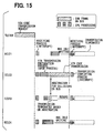
- the connector 51 of the tester 50 is connected to the connector 11, and a request for transmitting a VIN code is issued to each ECU 1, 2, 3, 4 inputted by the service person via an input device. Data flow of this operation is indicated with broken-line arrows.
- the ECU 1, 2, 3, 4 receives the request, the ECU 1, 2, 3, 4 activates its timer 1c, 2c, 3c, 4c to start timing the response start time. Only one of the ECUs 1, 2, 3, 4 transmits the VIN code to the tester 50 at a time.
- Data flow in the case that the ECU 1 transmits the VIN code to the tester 50 is indicated with a solid-line arrow. An order for transmitting the VIN code is predetermined based on the response start time.
- the response start time is set in ascending order of the ECU 1 (T1), the ECU 2 (T2), the ECU 3 (T3), and the ECU 4 (T4), that is, Tl ⁇ T2 ⁇ T3 ⁇ T4. If the ECU having the highest priority cannot transmit the VIN code due to failure or break, the ECU having next higher priority transmits the VIN code.
- each ECU 1, 2, 3, 4 sets a VIN code request flag VINReq to ON, and activates its timer 1c, 2c, 3c, 4c.
- the timer 1c, 2c, 3c, 4c times in a slot of a 1-ms process, that is, every one millisecond, based on an internal clock of the MC 1a, 2a, 3a, 4a.
- the 1-ms process will be discussed later.
- time count Tres of the timer reaches the response start time T1
- the ECU 1 starts transmitting the VIN code and clears the count Tres.
- the ECUN continues the count of the timer and monitors the VIN code transmission performed by the ECU 1 via the communication line L.
- the ECUN stops the count of the timer, clears the count, and stops monitoring.
- the response start time Tn of the ECUN is set with intervals, each of which is longer than the time required for transmitting the VIN code. More specifically, an interval is set longer than the time for which the ECU 1, 2, 3, 4 having one higher priority completes sending the data up to cs shown in Fig. 3A. Even when the ECU 1, 2, 3, 4 is unable to transmit the VIN code, the ECU 1, 2, 3, 4 having the next higher priority transmits the VIN code after it confirms the condition that the ECU 1, 2, 3, 4 with higher priority is unable to transmit the VIN code.
- the response start time T1, T2, T3, T4 of the ECU 1, 2, 3, 4 with the lowest priority, that is, having the slowest response start time T1, T2, T3, T4, is set equal to or shorter than the time that satisfies the OBD-II requirement. Therefore, the ECUs 1, 2, 3, 4 other than this ECU 1, 2, 3, 4 are unable to transmit the VIN code, the OBD-II requirement is satisfied by transmitting the VIN code by this ECU 1, 2, 3, 4.
- the ECU 1 When the ECU 1 has successfully transmitted the VIN code to the tester 50, other ECUs 2, 3, 4 do not transmit the VIN code. If the ECU 1 fails to transmit the VIN code, the ECU 2 that have the second highest priority transmits the VIN code when the response start time T2 has elapsed. If neither the ECU 1 nor the ECU 2 fails to transmit the VIN code, the ECUN having the next highest priority transmits the VIN code when the response start time Tn has elapsed. At this time, the other ECUs 1, 2, 3, 4 perform the same process described above.
- a VIN code request flag VINreq is set (ON).
- the flag VINreq indicates that the request has been received, and the count Tres of the timer is cleared (0) for activating the timer that counts down to the response start time.
- 1ms process shown in Fig. 6 is performed every one millisecond. In other words, when the flag VINReq is ON (S210: YES), the count Tres is incremented by 1 (S220).
- a monitoring process shown in Fig. 7 is performed in parallel with the 1ms process.
- Each ECU 1, 2, 3, 4 starts monitoring the communication line L when it receives the VIN code transmission request from the tester 50, and detects the target address Tgt to which another ECU 1, 2, 3,4 has transmitted the VIN code (S300). If the target address Tgt is the address F1 of the tester 50 (S310: YES), the ECU 1, 2, 3, 4 detects content Data of the data to determine whether it is a VIN code. If the content Data is a VIN code (S320: YES), it is determined that the VIN code has been transmitted to the tester 50 by another ECU 1, 2, 3, 4, and starts a completing process that will be discussed later (S330). If the address Tgt is not the address F1 (S310: NO) or the content Data is not a VIN code (S320: NO), the process is terminated.
- each ECU 1, 2, 3, 4 sets the VIN code request flag VINReq to OFF and clears the count Tres in the termination process. Then, the ECU 1, 2, 3, 4 completes the process.
- priorities for transmitting the VIN code to the tester 50 is given to the ECUs 1, 2, 3, 4. If the ECU 1, 2, 3, 4 with a high priority cannot successfully transmit the VIN code due to a failure or a line breakage, other ECUs 1, 2, 3, 4 transmit the VIN code in order of decreasing precedence. As a result, the VIN code is transmitted to the tester 50 responding to the request without fail.
- the ECU 1, 2, 3, 4 When the ECU 1, 2, 3, 4 receives the VIN code request from the tester 50, it starts monitoring the communication line L, and when the transmission process performed by another ECU 1, 2, 3, 4 has been completed, it terminates the rest of the VIN code transmission process and do not transmit the VIN code. In other words, the VIN code is not simultaneously transmitted from multiple ECUs 1, 2, 3, 4, and data collisions on the line L are less likely to occur. Therefore, the OBD-II requirement that the number of VIN codes transmitted from one vehicle must be one is satisfied.
- the nonvolatile memories 1d, 2d, 3d, 4d, included in the ECUs 1, 2, 3, 4 correspond to the storage means, and the MCs 1a, 2a, 3a, 4a correspond to the detecting means and the communication means.
- the timers 1c, 2c, 3c, 4c correspond the timing means.
- the response start time Tn of each ECU 1, 2, 3, 4 is fixed. However, the response start time Tn can be altered according to the circumstances.
- the ECU 1, 2, 3, 4 determines whether another ECUs 1, 2, 3, 4 with higher priority than itself is unable to transmit data during the normal operation of the ECU 1, 2, 3, 4 before the VIN code transmission request is issued. If it determines that one of the ECU 1, 2, 3, 4 with higher priority than itself is unable to transmit data, it shortens its response start time when the VIN code transmission request is issued.
- the response start time T2 of the ECU 2 is set longer than that of the ECU 1, which has higher priority than the ECU 2.
- the response start time T3 of the ECU 3 is set longer than the response start time T2 if the ECU 1, the ECU 2, and the ECU 3 are able to transmit data.
- the ECU 2 and the ECU 3 with lower priorities than the ECU 1 start monitoring the communication line L.
- the ECU 2 and the ECU 3 shorten their response start time T2, T3.
- the ECUN with lower priority shortens its response start time Tn by the response start time T1.
- Steps shown in S590-S630 are the same as steps of S210-S250 shown in Fig. 6. Therefore, the detailed discussion about the steps S590-S630 will not be discussed here.
- a variable j is set to a default value 1 (S510). It is determined whether the variable j is equal to or higher than a priority level n that is assigned to the ECU 1, 2, 3 (S520).
- the priority level is assigned to each ECU 1, 2, 3 in order of decreasing precedence starting from the ECU 1 having the highest priority, that is, having the shortest response start time.
- Each ECU 1, 2, 3 stores its priority level and other ECUs' priority levels in advance. Since the ECU 1, the ECU 2, and the ECU 3 have relationships of T1 ⁇ T2 ⁇ T3, their priority levels are 1, 2, and 3, respectively.
- step S530 more specifically, when the data that contains the source address Src indicative of the address of the ECU 1, 2, 3 with priority level j is detected on the line L, it is determined that the data is transmitted by the ECU 1, 2, 3.
- a time count Ej for measuring the time during which the ECU 1, 2, 3 with precedence j has not transmitted data is cleared (S540).
- thecountEj is incremented by 1 (S550). Then, it is determined whether the count Ej reaches a threshold time preset to the ECU 1, 2, 3 with precedence j for determining an incommunicable condition (S560). If the count Ej has reached the threshold time (S560: YES), it is determined that the ECU 1, 2, 3 with precedence j is under a communicable condition (S570). In other words, it is determined that the ECU 1, 2, 3 is under the incommunicable condition when the data supposed to be periodically transmitted has not been detected.
- the threshold time for incommunicable condition determination is set for each ECU1, 2, 3 based on a data transmission rate of the ECU 1, 2, 3 under the communicable condition. If the ECU 1 transmits data, such as engine revolution speed information, every 8ms, the threshold time may be set to 80msec.
- the system may be configured so that it determines the communicable condition when the data is transmitted from the ECU 1, 2, 3 after the incommunicable condition is determined.
- step S540 or S570 is completed, or it is determined that the count Ej has not exceeded the threshold time in step S560 (S560: NO)
- the variable j is incremented by 1 (S580) and the process is returned to step S520. If the variable j is equal to or higher than the priority level n, that is, the priority level expressed by the variable j is equal to or lower than the priority level n (S520: YES), steps S590 through S630 are performed in the same manner as steps S210 through S250 of the first embodiment, and this 1ms process is completed. In this 1ms process, it is determined whether any ECU 1, 2, 3 with higher priority than the priority level n is unable to transmit data exists.
- Avariable k is set to a default value 1 (S740). It is determined whether the variable k is equal to or higher than the priority level n (S750). If the variable k is lower than the priority level n, that is, the priority level expressed by the variable k is higher than the priority level n (S750: NO), it is determined whether the ECU 1, 2, 3 with the priority level k is determined that it has been under the incommunicable condition in step S570 (S760). If the ECU with precedence k is determined that it has been under the incommunicable condition (S760: YES), a fixed value . is subtracted from the response start time Tn (S770). In other words, the response start time Tn is shortened by the fixed value .. The fixed value . is set to the time required for the ECU to complete the VIN code transmission.
- step S770 If the ECU 1, 2, 3 with the priority level k is determined that it has been under the communicable condition (S760: NO), or after the completion of step S770, the variable k is incremented by 1 (S780) and the process is returned to step S750.
- the process is completed.
- the response start time Tn is shortened according to the number of ECUs 1, 2, 3 with the priority level higher than n under the incommunicable condition.
- the response start time Tn determined in this process is used in step S610 of the 1ms process shown in Fig. 10.
- the response start time is shortened so that the time at which the VIN code is transmitted after the VIN code transmission request is issued by the tester 50 is shortened. Furthermore, the usability of the communication line L can be improved by reducing unnecessary waiting time. It is determined whether the ECU is under the incommunicable condition based on whether the time during which the ECU has not transmitted data reaches the predetermined threshold time. Therefore, the determination for the data transmission condition of the ECU can be easily made. Furthermore, the waiting time is efficiently shortened and the usability of the communication line L is effectively improved since the response start time is shortened relative to the number of the ECUs under the incommunicable condition.
- Steps S510 through S580 shown in Fig. 10 and steps S730 through S780 shown in Fig. 11 correspond to the time shortening means.
- the fixed value . is subtracted from the response start time Tn.
- each ECU may store multiple values for the response start time Tn in advance, and select an appropriate value among those values based on the numbers and the kinds of the ECUs under the incommunicable condition.
- each ECU 1, 2, 3, 4 sets the VIN code request flag VINReq ON, and starts counting the time by activating the timer 1c, 2c, 3c, 4c.
- the time count Tres of the timer 1c reaches the response start time T1
- the ECU 1 starts the VIN code transmission process and clears the timer 1c.
- the ECUN monitors the transmission process performed by another ECU 2, 3, 4 via the communication line L, and they initialize (clear) the count Tres of the timer 2c, 3c, 4c when the start of the transmission process performed by the ECU 1 is detected. If the ECU 1 does not successfully transmit data to the tester 50 due to noise, the ECUN starts counting the time when the termination of the transmission process performed by the ECU 1 is detected.
- Each ECU 1, 2, 3, 4 can determine whether the VIN code has been successfully transmitted by another ECU 1, 2, 3, 4 based on the contents of the VIN code in the transmitted data of the cs value.
- Fig. 12 shows the case that the transmission process has been started by the ECU 1 but the VIN code date is not successfully transmitted. If the ECU 1 is under the incommunicable condition, the VIN code transmission process is not started by the ECU 1 even when the time reaches the response start time T1. As a result, the ECUN continues counting without initializing the count Tres of the timer 2c, 3c, 4c.
- a 1ms process shown in Fig. 13 if it is determined that the VIN code request flag VINReq is ON (S810: YES), it is then determined whether the transmission process has been performed by another ECU 1, 2, 3, 4 (S820).
- Each ECU 1, 2, 3, 4 is configured to start the transmission process when it receives the VIN code transmission request from the tester 50. Therefore, the ECU 1, 2, 3, 4 can determine whether the transmission process has been started by another ECU 1, 2, 3, 4 by detecting transmitted data on the communication line L.
- the ECU 1, 2, 3, 4 completes this 1ms process after performing the steps S840 through S870 in the same manner as steps S220 through 5250 of the first embodiment. If it is determined that the transmission process has been started by another ECU 1, 2, 3, 4 (S820: YES), the ECU 1, 2, 3, 4 completes this 1ms process after clearing the count Tres of the timer 1c, 2c, 3c, 4c (S830).
- each ECU 1, 2, 3, 4 continues the count of the timer 1c, 2c, 3c, 4c without clearing the count Tres after the response start time has elapsed when the ECU with higher priority is under the incommunicable condition. Therefore, the time between the issuance of the VIN code transmission request by the tester 50 and the start of the VIN code transmission (response waiting time) can be shortened. By reducing unnecessary waiting time, the usability of the communication line L can be improved.
- the vehicular electronic control system 20 is configured basically the same as the vehicular electronic control system 10 (Fig. 1).
- Each ECU 21, 22, 23, 24 includes a controller area network (CAN) driver/receiver as a communication unit (COM) 21b, 22b, 23b, 24b for performing data communication according to CAN, which is a commonly used protocol in an onboard network.
- CAN controller area network
- COM communication unit
- the electronic control system 20 is installed on the vehicle 100. It includes an engine ECU 21, a transmission ECU 22, a driving control ECU 23, and a body ECU 24.
- the ECUs 21, 22, 24, and 24 control an engine, an automatic transmission, a braking system, and power windows or power door locks, respectively.
- the COM 21b, 22b, 23b, 24b of each ECU 21, 22, 23, 24 performs communication using the CAN protocol.
- the COM 21b, 22b, 23b, 24b adds an identification code (CANID), which is assigned to the ECU 21, 22, 23, 24 and used for determining order of precedence, to a header of a frame that is transmitted.
- CANID identification code
- the COM 21b, 22b, 23b, 24b having the frame immediately starts transmitting the frame if the communication line L is not busy. If the line L is busy, it starts transmitting the frame when the line L becomes available. Therefore, if multiple ECUs 21, 22, 23, 24 are ready for frame transmission and start the frame transmission all at once when the line L becomes available, collisions of the frames occur on the line L.
- arbitration control for deciding which frame to give priority for processing using the CANID.
- the arbitration control is performed by using a method called nondestructive bitwise arbitration.
- a signal level on the line L is either dominant or recessive.
- the signal level on the line L is dominant.
- Logical values of the dominant level and the recessive level are 0 and 1, respectively.
- the CANID has a 4-bit (11-bit in the actual CAN protocol) construction, and three ECUs 21, 22, 23 start transmitting the frames at the same time, the CANIDs assigned to the frames from the first ECE 21, the second ECU 22, and the third ECU 23 are 0001B, 0010B, and 0100B, respectively.
- the signal level of the line L becomes dominant (0) even though the output of the third ECU 23 is recessive (1).
- priority is not given to the third ECU 23 at this time, and the third ECU 23 stops the frame transmission and enters a data receiving state.
- the signal level of the line L becomes dominant even though the output of the second ECU 22 is recessive. Therefore, priority is not given to the second ECU 22 at this time, and the second ECU 22 stops the frame transmission and enters a data receiving state. Thus, the first ECU 21 is given priority and continues sending the frame.
- an ECU that has transmitted a frame with the smallest logical value of the CANID gets priority when multiple frames are transmitted to a communication line.
- the logical values of the CANID are set in ascending order of the ECU 21, the ECU 22, the ECU 23, the ECU 24. In other words, the priorities in the arbitration control are given to the ECU 21, the ECU 22, the ECU 23, and the ECU 24 in that order.
- the communication processing for the vehicle identifying information between the tester 50 and the vehicular electronic control system 20 will be explained.
- the connector 51 of the tester 50 is connected to the connector 11 and the VIN code transmission requests are issued to all ECUs 21, 22, 23, 24 based on the input entered by an operator via the input device.
- the ECU 21, the ECU 22, the ECU 23, and the ECU 24 start the receiving processes for receiving the frames responding to the VIN code transmission requests via the line L. Then, each ECU 21, 22, 23, 24 performs a VIN code transmission preparation process at respective timing.
- each ECU 21, 22, 23, 24 reads the VIN code from its nonvolatile memory 1c, 2c, 3c, 4c and produces the frame for transmitting the VIN code.
- the reason why the time required for the VIN code transmission preparation process is different from ECU to ECU is because of the performance of each ECU 21, 22, 23, 24, for instance, a driving clock, and programs used in the ECU 21, 22, 23, 24.
- each ECU 21, 22, 23, 24 requests for starting the VIN code transmission to its COM 21b, 22b, 23b, 24b.
- the COM 21b, 22b, 23b, 24b starts transmitting the VIN code when the line L becomes available.
- the ECU 22 and the ECU 23 start transmitting the VIN code at the same time, and the transmission process of the ECU 23 is terminated based on the arbitration using the CANIDs, that is, the transmission process of the ECU 23 is terminated because the priority is not given in the arbitration.
- the COM 23b of the ECU 23 starts transmitting the VIN code when the line L becomes available.
- the ECU 22 transmits the VIN code to the tester 50.
- other ECUs 21, 23, 24 perform the receiving processes for receiving the frames of the VIN code transmission via the line L.
- the ECUs 21, 23, 24 request their COM 21b, 23b, 24b for termination of the VIN code transmission.
- the ECU 22 performs transmission completion process when the VIN code has been transmitted. If the VIN code is not successfully transmitted by the ECU 22, another ECU 21, 23, 24 starts the VIN code transmission.
- the ECU 21 starts transmitting the VIN code based on the arbitration using the CANIDs. If the ECU 21 has not successfully transmitted the VIN code, another ECU 23, 24 starts transmitting the VIN code.
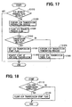
- the receiving process is started when data (frame) is detected the line L.
- the receiving process it is determined whether detected data is a VIN code transmission request issued by the tester 50 (S910).
- a VIN transmission check flag that indicates the VIN code has been successfully transmitted by another ECU 21, 22, 23, 24 is cleared (OFF) for initialization (S920). Then, a VIN request processing flag that indicates the VIN code transmission request issued by the tester 50 has been received is set (S930) and this process is completed. If it is determined that the detected data is not the VIN code transmission request (S910: NO), it is determined whether it is a VIN code transmission by another ECU 21, 22, 23, 24 (S940). More specifically, it is determined whether it is a VIN code transmission that has been successfully completed.
- the VIN transmission flag is set (S950), and the VIN request processing flag is cleared (S960).
- the VIN request processing request flag is cleared in step 5960 so that the VIN code transmission is not redundantly performed. It is determined a VIN transmission start flag is ON or OFF (S970). The VIN transmission start flag indicates that a start of the VIN code transmission is requested to the COM 21b, 22b, 23b, 24b.
- VIN transmission start flag is OFF, that is, the VIN code transmission start is not requested to the COM 21b, 22b, 23b, 24b (S970: OFF), this receiving process is completed. If the VIN transmission start flag is ON, that is, the VIN code transmission start is requested to the COM 21b, 22b, 23b, 24b (S970: NO), a VIN transmission terminating process for requesting for terminating the VIN code transmission to the COM 21b, 22b, 23b, 24b (S980). The VIN transmission start flag is cleared and this receiving process is completed.
- step S940 NO
- a receiving process appropriate for the detected data for instance, engine revolution speed data, is performed (S1000). Then, this receiving process is completed.
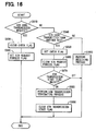
- a base processing shown in Fig. 17 will be explained. This base processing is performed at regular intervals predetermined for each ECU 21, 22, 23, 24, for instance, every 1ms, 4ms, and 8ms.
- the base processing is started, it is determined the VIN request processing flag is ON or OFF (S1010). If the VIN request processing flag is OFF (S1010: OFF), this base processing is completed. If the VIN request processing f lag is ON (S1010: ON), the VIN transmission preparation process for producing a frame for transmitting the VIN code is performed (S1020). Then, the VIN request processing flag is cleared (S1030).
- the VIN transmission check flag is ON or OFF (S1040). If the VIN transmission check flag is ON (S1040: OFF), the VIN transmission start flag is set ON (S1050). Then, transmission of the frame produced in the VIN transmission preparation process (S1020) to the tester 50 is requested the COM 21b, 22b, 23b, 24b (S1060). In other words, the start of the VIN code transmission is requested to the COM 21b, 22b, 23b, 24b. Then, this base processing is completed. If the line L is busy, the COM 21b, 22b, 23b, 24b starts transmitting the frame when the line L becomes available. When the VIN code transmission by another ECU 21, 22, 23, 24 is detected (S940) before transmitting the frame, the ECU 21, 22, 23, 24 requests the VIN code transmission terminating request to the COM 21b, 22b, 23b, 24b (S980).
- step S1040 If the VIN transmission check flag is ON (S1040: ON) in step S1040, the VIN transmission terminating process for terminating the VIN code transmission is performed (S1070). The VIN transmission check flag is cleared (S1080), and this base process is completed. The VIN transmission check flag is set ON in step S1040 after the process of step S1010 in this base process is performed and the VIN transmission check flag is set ON in the receiving process S950. When the VIN code transmission by another ECU is detected while the VIN transmission preparation process (S1020) is performed, the process proceeds to step S1070.
- a transmission completing process will be discussed referring to Fig. 18.
- This transmission completing process is started by completing data (frame) transmission.
- the transmission completing process it is determined whether the data that has been transmitted is VIN code transmiss ion (S1110). I f it is not a completion of the VIN code transmission (S1110: NO), this transmission completing process is completed. If it is the completion of the VIN code transmission (S1110: YES), the VIN transmission start flag is cleared (S1120), and this transmission completing process is completed.
- the electronic control system 20 priorities are not assigned to the ECUs 21, 22, 23, 24 for transmitting the VIN code to the tester 50.
- the VIN code is transmitted by the ECU 21, 22, 23, 24 that has completed the transmission preparation process first.
- other ECUs 21, 22, 23, 24 send the VIN code in order of precedence. Therefore, the electronic control system 20 responds to the VIN code request issued by the tester 50 without fail.
- Each ECU 21, 22, 23, 24 monitors the line L.
- the ECU 21, 22, 23, 24 terminates the VIN code transmission process and does not transmit the VIN code. Therefore, the OBD-II requirement that the number of VIN codes transmitted from one vehicle must be one is satisfied.
- the nonvolatile memory 1d, 2d, 3d, 4d, the COM 21b, 22b, 23b, 24b, and the MC 1a, 2a, 3a, 4a of each ECU 21, 22, 23, 24 correspond to the storage means, the communication means, and the detecting means, respectively.
- the engine ECUs, the transmission ECUs, the driving control ECUs, and the body ECUs are provided as electronic control units included in the vehicular electronic control system of the present invention.
- other electronic control units for controlling other components of the vehicle can be included.
- priorities are assigned to multiple ECUs in the above embodiments. However, the priorities are assigned as appropriate for design.
Landscapes
- Engineering & Computer Science (AREA)
- Automation & Control Theory (AREA)
- Mechanical Engineering (AREA)
- Small-Scale Networks (AREA)
- Combined Controls Of Internal Combustion Engines (AREA)
Abstract
Description
Claims (26)
- An vehicular electronic control system (10) having a plurality of electronic control units (1, 2, 3, 4) that are intercommunicative with each other via a communication line (L) for data transmission and configured to transmit vehicle identifying information, which is unique to the vehicle, on demand from an external scan tool (50) connected to the communication line (L), wherein each electronic control unit (1, 2, 3, 4) comprises:a storing means (1d, 2d, 3d, 4d) for storing the vehicle identifying information;a detecting means (1a, 2a, 3a, 4a) for monitoring the communication line (L) and detecting an output indicative of the vehicle identifying information sent from any one of other electronic control units (1, 2, 3, 4) to the external scan tool (50);a timing means (1a, 2a, 3a, 4a) for timing an elapsed time since the electronic control unit (1, 2, 3, 4) has received a vehicle identifying information transmission request from the external scan tool (50) and a response start time (T1, T2, T3, T4) that is preset for each electronic control unit (1, 2, 3, 4) based on order of precedence; anda communication means (1b, 2b, 3b, 4b) for reading the vehicle identifying information from the storing means (1d, 2d, 3d, 4d) and transmitting the vehicle identifying information to the external scan tool (50) if the detecting means has not detected the output indicative of the vehicle identifying information to the external scan tool (50) when the response start time (t1, T2, T3, T4) has elapsed.
- The vehicular electronic control system (10) according to claim 1, wherein the detecting means (1a, 2a, 3a, 4a) starts monitoring the communication line (L) for detecting the output when the electronic control unit (1, 2, 3, 4) has received the vehicle identifying information from the external scan tool (50).
- The vehicular electronic control system (10) according to claim 1 or 2, wherein the detecting means (1a, 2a, 3a, 4a) detects a target address (Tgt) to which data on the communication line (L) is transmitted, and determines whether a content of the data is the vehicle identifying information only when the target address (Tgt) is an address of the external scan tool (50).
- The vehicular electronic control system (10) according to any one of claims 1 through 3, wherein each electronic control unit (1, 2, 3, 4) terminates processes performed by the detecting means (1a, 2a, 3a, 4a) and the timing means (1a, 2a, 3a, 4a) when the output sent from any one of other electronic control units (1, 2, 3, 4) has transmitted the vehicle identifying information to the external scan tool (50).
- The vehicular electronic control system (10) according to any one of claims 1 through 4, wherein the response start time (T1, T2, T3, T4) of each electronic control unit (1, 2, 3, 4) is set at intervals, each of which is longer than a time required for transmitting the vehicle identifying information.
- The vehicular electronic control system (10) according to any one of claims 1 through 4, wherein the timing means (1c, 2c, 3c, 4c) of each electronic control unit (1, 2, 3, 4) stops timing when another electronic control unit (1, 2, 3, 4) has started transmitting the vehicle identifying information and starts timing an elapsed time since the other electronic control unit (1, 2, 3, 4) has terminated the transmission in a case that the vehicle identifying information is not successfully transmitted.
- The vehicular electronic control system (10) according to any one of claims 1 through 6, wherein:each electronic control unit (1, 2, 3, 4) further comprises a time shortening means (S510-S580, S730-S780);the communication means (1b, 2b, 3b, 4b) of each electronic control unit (1, 2, 3, 4) determines whether other electronic control units (1, 2, 3, 4) having shorter response start time (T1, T2, T3, T4) is under an incommunicable condition; andthe time shortening means (S510-S580, S730-S780) shortens the response start time (T1, T2, T3, T4) when the communication means (1b, 2b, 3b, 4b) has determined that another electronic control unit (1, 2, 3, 4) is under the incommunicable condition.
- The vehicular electronic control system (10) according to claim 7, wherein the time shortening means (S510-S580, S730-S780) of each electronic control unit (1, 2, 3, 4) monitors the communication line (L), and determines that another electronic control unit (1, 2, 3, 4) having shorter response start time (T1, T2, T3, T4) is in the incommunicable condition if the electronic control unit (1, 2, 3, 4) has not transmitted data for longer than a predetermined time.
- The vehicular electronic control system (10) according to claim 7 or 8, wherein the time shortening means (S510-S580, S730-S780) of each electronic control unit (1, 2, 3, 4) shortens the response start time (t1, T2, T3, T4) so that the response start time (T1, T2, T3, T4) becomes shorter as the number of electronic control unit (1, 2, 3, 4) determined as in the incommunicable condition increases.
- An electronic control unit (1, 2, 3, 4) that is installed on a vehicle (100), intercommunicative with other electronic control units (1, 2, 3, 4) via a communication line (L), and capable of transmitting vehicle identifying information of the vehicle (100) on demand from an external scan tool (50) connected to the electronic control unit (1, 2, 3, 4) via the communication line (L), comprising:a storing means (1d, 2d, 3d, 4d) for storing the vehicle identifying information;a detecting means (1a, 2a, 3a, 4a) for monitoring the communication line (L) and detecting an output indicative of the vehicle identifying information sent from any one of other electronic control units (1, 2, 3, 4) to the external scan tool (50);a timing means (1c, 2c, 3c, 4c) for timing an elapsed time since the electronic control unit (1, 2, 3, 4) has received a vehicle identifying information transmission request from the external scan tool (50) and a response start time (T1, T2, T3, T4) that is preset for each electronic control unit (1, 2, 3, 4) based on order of precedence; anda communication means (1b, 2b, 3b, 4b) for reading the vehicle identifying information from the storing means (1d, 2d, 3d, 4d) and transmitting the vehicle identifying information to the external scan tool (50) if the detecting means (1a, 2a, 3a, 4a) has not detected the output indicative of the vehicle identifying information to the external scan tool (50) when the response start time (T1, T2, T3, T4) has elapsed.
- The electronic control unit (1, 2, 3, 4) according to claim 10, wherein the detecting means (1a, 2a, 3a, 4a) starts monitoring the communication line (L) for detecting the output when the electronic control unit (1, 2, 3, 3) has received the vehicle identifying information from the external scan tool (50).
- The electronic control unit (1, 2, 3, 4) according to claim 10 or 11, wherein the detecting means (1a, 2a, 3a, 4a) detects a target address (Tgt) to which data on the communication line is transmitted, and determines whether a content of the data is the vehicle identifying information only when the target address (Tgt) is an address of the external scan tool (50).
- The electronic control unit (10) according to any one of claims 10 through 12, wherein the detecting means (1a, 2a, 3a, 4a) terminates processes performed by the detecting means (1a, 2a, 3a, 4a) and the timing means (1c, 2c, 3c, 4c) when the output sent from any one of other electronic control units (1, 2, 3, 4) has transmitted the vehicle identifying information to the external scan tool (50).
- The electronic control unit (1, 2, 3, 4) according to any one of claims 10 through 13, wherein the response start time (T1, T2, T3, T4) is set at intervals, each of which is longer than a time required for transmitting the vehicle identifying information.
- The electronic control unit (1, 2, 3, 4) according to any one of claims 10 through 13, wherein the timing means (1c, 2c, 3c, 4c) stops timing when another electronic control unit (1, 2, 3, 4) has started transmitting the vehicle identifying information and starts timing an elapsed time since the other electronic control unit (1, 2, 3, 4) has terminated the transmission in a case that the vehicle identifying information is not successfully transmitted.
- The electronic control unit (1, 2, 3, 4) according to any one of claims 10 through 15, wherein:the communication means (1b, 2b, 3b, 4b) further comprises a time shortening means (S510-S580, S730-S780);the communication means (1b, 2b, 3b, 4b) determines whether other electronic control units (1, 2, 3, 4) having shorter response start time (T1, T2, T3, T4) is under an incommunicable condition; andthe time shortening means (S510-S580, S730-S780) shortens the response start time (T1, T2, T3, T4) when the communication means (1b, 2b, 3b, 4b) has determined that another electronic control unit (1, 2, 3, 4) is under the incommunicable condition.
- The electronic control unit (1, 2, 3, 4) according to claim 16, wherein the time shortening means (S510-S580, S730-S780) monitors the communication line (L) and determines that another electronic control unit (1, 2, 3, 4) having shorter response start time (T1, T2, T3, T4) is in the incommunicable condition if the electronic control unit (1, 2, 3, 4) has not transmitted data for longer than a predetermined time.
- The electronic control unit (1, 2, 3, 4) according to claim 16 or 17, wherein the time shortening means (S510-S580, S730-S780) shortens the response start time (T1, T2, T3, T4) so that the response start time (T1, T2, T3, T4) becomes shorter as the number of electronic control unit (1, 2, 3, 4) determined as in the incommunicable condition increases.
- A program (S110, S120, S210-S250, S310-S330, S410, S420, S510-S630, S710-S780, S810-S870) for operating computing means (1, 2, 3, 4) as the detecting means (1a, 2a, 3a, 4a), the timing means (1c, 2c, 3c, 4c), and the communication means (1b, 2b, 3b, 4b) in the electronic control unit (1, 2, 3, 4) claimed in claim 10.
- An vehicular electronic control system (20) having a plurality of electronic control units (21, 22, 23 24) that are intercommunicative with each other via a communication line (L) for data transmission and configured to transmit vehicle identifying information, which is unique to the vehicle, on demand from an external scan tool (50) connected to the communication line (L), wherein each electronic control unit (21, 22, 23, 24) comprises:a storing means (1d, 2d, 3d, 4d) for storing the vehicle identifying information;a detecting means (1a, 2a, 3a, 4a) for monitoring the communication line (L) and detecting an output indicative of the vehicle identifying information sent from any one of other electronic control units (21, 22, 23, 24) to the external scan tool (50);a communication means (21b, 22b, 23b, 24b) for transmitting data that has been requested; anda transmission requesting means (1a, 2a, 3a, 4a) for requesting the communication means (21b, 22b, 23b, 24b) to transmit the vehicle identifying information stored in the storing means (1d, 2d, 3d, 4d) to the external scan tool (50) if the detecting means (1a, 2a, 3a, 4a) has not detected the output when the electronic control unit (21, 22, 23, 24) has received a vehicle identifying information transmission request from the external scan tool (50) and to stop the vehicle identifying information transmission when the detecting means (1a, 2a, 3a, 4a) has detected the output from another electronic control unit (21, 22, 23, 24) after the electronic control unit (21, 22, 23, 24) has received the request, whereinthe communication means (21b, 22b, 23b, 24b) transmits the data upon the data transmission request if the communication line (L) is available, transmits the data when the communication line (L) becomes available if the communication line (L) is busy at a time when the data transmission request is received, and transmits the data according to a decision of arbitration made based on order of precedence predetermined for each electronic control unit (21, 22, 23, 24) when another electronic unit (21, 22, 23, 24) is ready for data transmission at the same time.
- The vehicular electronic control system (20) according to claim 20, wherein the communication means (21b, 22b, 23b, 24b) transmits the data with an identification code used for determining the order of precedence and stops the data transmission if the identification code does not match an identification code on the communication line (L).
- An electronic control unit (21, 22, 23, 24) that is installed on a vehicle (100), intercommunicative with other electronic control units (21, 22, 23, 24) via a communication line (L), and capable of transmitting vehicle identifying information of the vehicle (100) on demand from an external scan tool (50) connected to the electronic control unit (21, 22, 23, 24) via the communication line (L), comprising:a storing means (1d, 2d, 3d, 4d) for storing the vehicle identifying information;a detecting means (1a, 2a, 3a, 4a) for monitoring the communication line (L) and detecting an output indicative of the vehicle identifying information sent from any one of other electronic control units (21, 22, 23, 24) to the external scan tool (50);a communication means (21b, 22b, 23b, 24b) for transmitting data that has been requested; anda transmission requesting means (1a, 2a, 3a, 4a) for requesting the communication means (21b, 22b, 23b, 24b) to transmit the vehicle identifying information stored in the storing means (1d, 2d, 3d, 4d) to the external scan tool (50) if the detecting means (1a, 2a, 3a, 4a) has not detected the output when the electronic control unit (21, 22, 23, 24) has received a vehicle identifying information transmission request from the external scan tool (50) and to stop the vehicle identifying information transmission when the detecting means (1a, 2a, 3a, 4a) has detected the output from another electronic control unit (21, 22, 23, 24) after the electronic control unit (21, 22, 23, 24) has received the request, whereinthe communication means (21b, 22b, 23b, 24b) transmits the data upon the data transmission request if the communication line (L) is available, transmits the data when the communication line (L) becomes available if the communication line (L) is busy at a time when the data transmission request is received, and transmits the data according to a decision of arbitration made based on order of precedence predetermined for each electronic control unit (21, 22, 23, 24) when another electronic unit (21, 22, 23, 24) is ready for data transmission at the same time.
- The electronic control unit (21, 22, 23, 24) according to the claim 22, wherein the communication means (21b, 22b, 23b, 24b) transmits the data with an identification code used for determining the order of precedence and stops the data transmission if the identification code does not match an identification code on the communication line (L).
- A program (S910-S990, S1010-S1080, S1110, S1120) foroperating computing means (21, 22, 23, 24) as the detecting means (21a, 22a, 23a, 24a) and the transmission requesting means (21a, 22a, 23a, 24a) in the electronic control unit (21, 22, 23, 24) claimed in claim 22 or 23.
- A storage medium (1d, 2d, 3d, 4d) for storing the program (S110, S120, S210-S250, S310-S330, S410, S420, S510-S630, S710-S780, S810-S870) claimed in claim 19, wherein the storage medium is computer-readable.
- A storage medium for storing the program (S910-S990, S1010-S1080, S1110, S1120) claimed in claim 24, wherein the storage medium (1d, 2d, 3d, 4d) is computer-readable.
Applications Claiming Priority (4)
| Application Number | Priority Date | Filing Date | Title |
|---|---|---|---|
| JP2002299082 | 2002-10-11 | ||
| JP2002299082 | 2002-10-11 | ||
| JP2003308999A JP4069836B2 (en) | 2002-10-11 | 2003-09-01 | Electronic control device for vehicle, electronic control unit, program and recording medium |
| JP2003308999 | 2003-09-01 |
Publications (3)
| Publication Number | Publication Date |
|---|---|
| EP1407936A2 true EP1407936A2 (en) | 2004-04-14 |
| EP1407936A3 EP1407936A3 (en) | 2005-07-27 |
| EP1407936B1 EP1407936B1 (en) | 2006-12-20 |
Family
ID=32032963
Family Applications (1)
| Application Number | Title | Priority Date | Filing Date |
|---|---|---|---|
| EP03022791A Expired - Lifetime EP1407936B1 (en) | 2002-10-11 | 2003-10-10 | Vehicular electronic control system and electronic control unit, program, and storing member for the same |
Country Status (4)
| Country | Link |
|---|---|
| US (1) | US6799106B2 (en) |
| EP (1) | EP1407936B1 (en) |
| JP (1) | JP4069836B2 (en) |
| DE (1) | DE60310492T2 (en) |
Cited By (3)
| Publication number | Priority date | Publication date | Assignee | Title |
|---|---|---|---|---|
| EP1826386A1 (en) | 2006-02-24 | 2007-08-29 | Beru Aktiengesellschaft | Combustion engines for vehicles, in particular diesel engines |
| CN103631247A (en) * | 2012-08-20 | 2014-03-12 | 北汽福田汽车股份有限公司 | A usage life test system for an electric control product of an automobile |
| WO2021213092A1 (en) * | 2020-09-08 | 2021-10-28 | 上海星融汽车科技有限公司 | Central ecu development and testing system |
Families Citing this family (91)
| Publication number | Priority date | Publication date | Assignee | Title |
|---|---|---|---|---|
| US8958998B2 (en) | 1997-11-03 | 2015-02-17 | Midtronics, Inc. | Electronic battery tester with network communication |
| US7446536B2 (en) * | 2000-03-27 | 2008-11-04 | Midtronics, Inc. | Scan tool for electronic battery tester |
| US9255955B2 (en) | 2003-09-05 | 2016-02-09 | Midtronics, Inc. | Method and apparatus for measuring a parameter of a vehicle electrical system |
| US9018958B2 (en) | 2003-09-05 | 2015-04-28 | Midtronics, Inc. | Method and apparatus for measuring a parameter of a vehicle electrical system |
| US9496720B2 (en) | 2004-08-20 | 2016-11-15 | Midtronics, Inc. | System for automatically gathering battery information |
| US8344685B2 (en) | 2004-08-20 | 2013-01-01 | Midtronics, Inc. | System for automatically gathering battery information |
| US7630801B2 (en) * | 2005-06-16 | 2009-12-08 | Ford Motor Company | System and method for retrieving and displaying vehicle control unit data |
| US9117319B2 (en) * | 2005-06-30 | 2015-08-25 | Innova Electronics, Inc. | Handheld automotive diagnostic tool with VIN decoder and communication system |
| US7464203B2 (en) * | 2005-07-29 | 2008-12-09 | Gm Global Technology Operations, Inc. | Method of validating plurality of data during serial communication using a dual path across a single serial link |
| CA2619428C (en) | 2005-08-18 | 2013-10-22 | Environmental Systems Products Holdings Inc. | System and method for testing the integrity of a vehicle testing/diagnostic system |
| US7533322B2 (en) * | 2005-11-03 | 2009-05-12 | Gm Global Technology Operations, Inc. | Method and system for performing function-specific memory checks within a vehicle-based control system |
| JP2007240436A (en) * | 2006-03-10 | 2007-09-20 | Denso Corp | Vehicle diagnostic system |
| EP2025097A2 (en) * | 2006-05-18 | 2009-02-18 | Nxp B.V. | Gateway for a data bus system |
| US7819032B2 (en) * | 2006-10-31 | 2010-10-26 | Shimano Inc. | Testing tool for electric bicycle devices |
| GB2491304B (en) | 2007-07-17 | 2013-01-09 | Midtronics Inc | Battery tester and electric vehicle |
| US9274157B2 (en) * | 2007-07-17 | 2016-03-01 | Midtronics, Inc. | Battery tester for electric vehicle |
| JP5111185B2 (en) * | 2008-03-24 | 2012-12-26 | 株式会社クボタ | Data communication system for work equipment |
| JP5111184B2 (en) * | 2008-03-24 | 2012-12-26 | 株式会社クボタ | Data communication system for work equipment |
| US8909416B2 (en) * | 2008-04-14 | 2014-12-09 | Innova Electronics, Inc. | Handheld scan tool with fixed solution capability |
| JP4475345B2 (en) * | 2008-04-25 | 2010-06-09 | 株式会社デンソー | Electronic control unit |
| JP4475346B2 (en) * | 2008-05-13 | 2010-06-09 | トヨタ自動車株式会社 | Fault diagnosis system and in-vehicle ECU used therefor |
| US8056538B2 (en) * | 2008-12-02 | 2011-11-15 | GM Global Technology Operations LLC | Method and system to prevent unauthorized uses of engine controllers |
| US20120179330A1 (en) * | 2009-06-17 | 2012-07-12 | Volvo Lastavagnar Ab | Function activation |
| DE102009028516A1 (en) * | 2009-08-13 | 2011-02-17 | Zf Friedrichshafen Ag | Method for detecting and configuring powertrain components |
| US8380389B2 (en) * | 2009-11-30 | 2013-02-19 | Honeywell International Inc. | Health monitoring systems and methods with vehicle identification |
| US9588185B2 (en) | 2010-02-25 | 2017-03-07 | Keith S. Champlin | Method and apparatus for detecting cell deterioration in an electrochemical cell or battery |
| US9425487B2 (en) * | 2010-03-03 | 2016-08-23 | Midtronics, Inc. | Monitor for front terminal batteries |
| US9229062B2 (en) | 2010-05-27 | 2016-01-05 | Midtronics, Inc. | Electronic storage battery diagnostic system |
| US10046649B2 (en) | 2012-06-28 | 2018-08-14 | Midtronics, Inc. | Hybrid and electric vehicle battery pack maintenance device |
| JP5829681B2 (en) | 2010-06-03 | 2015-12-09 | ミッドトロニクス インコーポレイテッド | Maintenance of battery packs for electric vehicles |
| US11740294B2 (en) | 2010-06-03 | 2023-08-29 | Midtronics, Inc. | High use battery pack maintenance |
| US9419311B2 (en) | 2010-06-18 | 2016-08-16 | Midtronics, Inc. | Battery maintenance device with thermal buffer |
| US9201120B2 (en) | 2010-08-12 | 2015-12-01 | Midtronics, Inc. | Electronic battery tester for testing storage battery |
| US9117321B2 (en) | 2010-08-18 | 2015-08-25 | Snap-On Incorporated | Method and apparatus to use remote and local control modes to acquire and visually present data |
| US20120044527A1 (en) * | 2010-08-18 | 2012-02-23 | Snap-On Incorporated | Apparatus and Method for Controlled Ethernet Switching |
| EP3432150B1 (en) | 2010-12-13 | 2021-01-20 | Nokia Technologies Oy | Method and apparatus for 3d capture synchronisation |
| US9119655B2 (en) | 2012-08-03 | 2015-09-01 | Stryker Corporation | Surgical manipulator capable of controlling a surgical instrument in multiple modes |
| US9921712B2 (en) | 2010-12-29 | 2018-03-20 | Mako Surgical Corp. | System and method for providing substantially stable control of a surgical tool |
| JP5500153B2 (en) * | 2011-11-09 | 2014-05-21 | 株式会社デンソー | Vehicle communication device and vehicle data communication system using the vehicle communication device |
| US10429449B2 (en) | 2011-11-10 | 2019-10-01 | Midtronics, Inc. | Battery pack tester |
| US11325479B2 (en) | 2012-06-28 | 2022-05-10 | Midtronics, Inc. | Hybrid and electric vehicle battery maintenance device |
| US9851411B2 (en) | 2012-06-28 | 2017-12-26 | Keith S. Champlin | Suppressing HF cable oscillations during dynamic measurements of cells and batteries |
| US9820818B2 (en) | 2012-08-03 | 2017-11-21 | Stryker Corporation | System and method for controlling a surgical manipulator based on implant parameters |
| US9226796B2 (en) | 2012-08-03 | 2016-01-05 | Stryker Corporation | Method for detecting a disturbance as an energy applicator of a surgical instrument traverses a cutting path |
| CA2879414A1 (en) | 2012-08-03 | 2014-02-06 | Stryker Corporation | Systems and methods for robotic surgery |
| KR101378277B1 (en) | 2012-12-28 | 2014-03-24 | 주식회사 현대케피코 | Ecu control and monitoring device for vechicle |
| US9244100B2 (en) | 2013-03-15 | 2016-01-26 | Midtronics, Inc. | Current clamp with jaw closure detection |
| US9312575B2 (en) | 2013-05-16 | 2016-04-12 | Midtronics, Inc. | Battery testing system and method |
| US10843574B2 (en) | 2013-12-12 | 2020-11-24 | Midtronics, Inc. | Calibration and programming of in-vehicle battery sensors |
| US9751422B2 (en) * | 2014-01-15 | 2017-09-05 | Bayerische Motoren Werke Aktiengesellschaft | Device for switching a mode of a vehicle |
| US9923289B2 (en) | 2014-01-16 | 2018-03-20 | Midtronics, Inc. | Battery clamp with endoskeleton design |
| US10473555B2 (en) | 2014-07-14 | 2019-11-12 | Midtronics, Inc. | Automotive maintenance system |
| US10222397B2 (en) | 2014-09-26 | 2019-03-05 | Midtronics, Inc. | Cable connector for electronic battery tester |
| US10317468B2 (en) | 2015-01-26 | 2019-06-11 | Midtronics, Inc. | Alternator tester |
| WO2016185360A1 (en) * | 2015-05-19 | 2016-11-24 | Hex Microsystems (Pty) Ltd | System and method for transferring diagnostic commands to a vehicle |
| US10706642B2 (en) * | 2015-09-24 | 2020-07-07 | Ford Global Technologies, Llc | Efficient telematics data upload |
| US9966676B2 (en) | 2015-09-28 | 2018-05-08 | Midtronics, Inc. | Kelvin connector adapter for storage battery |
| JP6443372B2 (en) * | 2016-03-24 | 2018-12-26 | トヨタ自動車株式会社 | Software allocation system for vehicles |
| US10608353B2 (en) | 2016-06-28 | 2020-03-31 | Midtronics, Inc. | Battery clamp |
| US10140116B2 (en) * | 2016-09-26 | 2018-11-27 | Ford Global Technologies, Llc | In-vehicle auxiliary memory storage |
| US11054480B2 (en) | 2016-10-25 | 2021-07-06 | Midtronics, Inc. | Electrical load for electronic battery tester and electronic battery tester including such electrical load |
| US12320857B2 (en) | 2016-10-25 | 2025-06-03 | Midtronics, Inc. | Electrical load for electronic battery tester and electronic battery tester including such electrical load |
| WO2018112025A1 (en) | 2016-12-16 | 2018-06-21 | Mako Surgical Corp. | Techniques for modifying tool operation in a surgical robotic system based on comparing actual and commanded states of the tool relative to a surgical site |
| JP6493381B2 (en) * | 2016-12-26 | 2019-04-03 | トヨタ自動車株式会社 | In-vehicle communication system |
| JP7094670B2 (en) * | 2017-07-03 | 2022-07-04 | 矢崎総業株式会社 | Setting device and computer |
| CN111630881B (en) * | 2018-01-26 | 2023-03-31 | 株式会社多田野 | Wireless communication device, work vehicle, and wireless communication system for work vehicle |
| JP6841248B2 (en) * | 2018-02-13 | 2021-03-10 | トヨタ自動車株式会社 | Autonomous driving system |
| KR102523250B1 (en) * | 2018-09-20 | 2023-04-20 | 현대자동차주식회사 | Control apparatus for vechicle, vehicle, and controlling method for vehicle |
| US11513160B2 (en) | 2018-11-29 | 2022-11-29 | Midtronics, Inc. | Vehicle battery maintenance device |
| US11566972B2 (en) | 2019-07-31 | 2023-01-31 | Midtronics, Inc. | Tire tread gauge using visual indicator |
| JP7395865B2 (en) * | 2019-07-31 | 2023-12-12 | マツダ株式会社 | Vehicle control system and vehicle control system design method |
| US11545839B2 (en) | 2019-11-05 | 2023-01-03 | Midtronics, Inc. | System for charging a series of connected batteries |
| US11668779B2 (en) | 2019-11-11 | 2023-06-06 | Midtronics, Inc. | Hybrid and electric vehicle battery pack maintenance device |
| US11474153B2 (en) | 2019-11-12 | 2022-10-18 | Midtronics, Inc. | Battery pack maintenance system |
| US11973202B2 (en) | 2019-12-31 | 2024-04-30 | Midtronics, Inc. | Intelligent module interface for battery maintenance device |
| DE102020216599A1 (en) | 2019-12-31 | 2021-07-01 | Midtronics, Inc. | Intelligent module interface for a battery maintenance device |
| US11486930B2 (en) | 2020-01-23 | 2022-11-01 | Midtronics, Inc. | Electronic battery tester with battery clamp storage holsters |
| US11574510B2 (en) | 2020-03-30 | 2023-02-07 | Innova Electronics Corporation | Multi-functional automotive diagnostic tablet with interchangeable function-specific cartridges |
| US11967189B2 (en) | 2020-04-20 | 2024-04-23 | Innova Electronics Corporation | Router for communicating vehicle data to a vehicle resource |
| US11651628B2 (en) | 2020-04-20 | 2023-05-16 | Innova Electronics Corporation | Router for vehicle diagnostic system |
| US11539714B2 (en) | 2020-09-17 | 2022-12-27 | Ford Global Technologies, Llc | Assigning categories for messages and symmetric key per category to localize the impact in case of key compromise |
| US11381421B2 (en) * | 2020-09-17 | 2022-07-05 | Ford Global Technologies, Llc | Using signal rating to identify security critical CAN messages and nodes for efficient implementation of distributed network security features |
| CN112594078B (en) * | 2020-12-07 | 2022-07-01 | 重庆潍柴发动机有限公司 | Preemptive redundant electric control system and method for marine engine |
| CN112731907B (en) * | 2020-12-30 | 2022-04-26 | 东风汽车有限公司 | Vehicle-mounted controller fault parallel injection testing method, electronic equipment and system |
| US12517178B2 (en) | 2021-05-27 | 2026-01-06 | Midtronics, Inc. | Battery monitoring system |
| US12555965B2 (en) | 2021-08-24 | 2026-02-17 | Midtronics, Inc. | Power adapter for automotive vehicle maintenance device |
| CN113734072B (en) * | 2021-09-15 | 2024-04-09 | 重庆长安汽车股份有限公司 | Vehicle body domain open interface control system and vehicle |
| US12330513B2 (en) | 2022-02-14 | 2025-06-17 | Midtronics, Inc. | Battery maintenance device with high voltage connector |
| US12392833B2 (en) | 2022-05-09 | 2025-08-19 | Midtronics, Inc. | Electronic battery tester |
| CN115509198B (en) * | 2022-08-31 | 2024-12-27 | 长城汽车股份有限公司 | Method, device, electronic equipment and storage medium for determining Electronic Control Unit (ECU) |
| CN119026621A (en) * | 2024-07-15 | 2024-11-26 | 陕汽集团商用车有限公司 | A VIN code reading and writing system and method based on new energy commercial vehicles |
Family Cites Families (6)
| Publication number | Priority date | Publication date | Assignee | Title |
|---|---|---|---|---|
| JPH08265880A (en) * | 1995-03-23 | 1996-10-11 | Nippondenso Co Ltd | Communication system |
| US6011460A (en) * | 1996-08-22 | 2000-01-04 | Flick; Kenneth E. | Vehicle security system for a vehicle having a data communications bus and related methods |
| US6505106B1 (en) * | 1999-05-06 | 2003-01-07 | International Business Machines Corporation | Analysis and profiling of vehicle fleet data |
| US6636790B1 (en) * | 2000-07-25 | 2003-10-21 | Reynolds And Reynolds Holdings, Inc. | Wireless diagnostic system and method for monitoring vehicles |
| DE10219832B4 (en) * | 2002-05-03 | 2005-12-01 | Daimlerchrysler Ag | Method for coding control devices in means of transport |
| US7020815B2 (en) * | 2002-08-29 | 2006-03-28 | Micron Technology, Inc. | Memory technology test apparatus |
-
2003
- 2003-09-01 JP JP2003308999A patent/JP4069836B2/en not_active Expired - Fee Related
- 2003-10-10 EP EP03022791A patent/EP1407936B1/en not_active Expired - Lifetime
- 2003-10-10 DE DE60310492T patent/DE60310492T2/en not_active Expired - Lifetime
- 2003-10-14 US US10/682,871 patent/US6799106B2/en not_active Expired - Lifetime
Cited By (4)
| Publication number | Priority date | Publication date | Assignee | Title |
|---|---|---|---|---|
| EP1826386A1 (en) | 2006-02-24 | 2007-08-29 | Beru Aktiengesellschaft | Combustion engines for vehicles, in particular diesel engines |
| CN103631247A (en) * | 2012-08-20 | 2014-03-12 | 北汽福田汽车股份有限公司 | A usage life test system for an electric control product of an automobile |
| CN103631247B (en) * | 2012-08-20 | 2016-08-24 | 北汽福田汽车股份有限公司 | A kind of life-span test system of the electric control product of automobile |
| WO2021213092A1 (en) * | 2020-09-08 | 2021-10-28 | 上海星融汽车科技有限公司 | Central ecu development and testing system |
Also Published As
| Publication number | Publication date |
|---|---|
| US20040088087A1 (en) | 2004-05-06 |
| EP1407936B1 (en) | 2006-12-20 |
| DE60310492T2 (en) | 2007-09-27 |
| DE60310492D1 (en) | 2007-02-01 |
| EP1407936A3 (en) | 2005-07-27 |
| JP4069836B2 (en) | 2008-04-02 |
| US6799106B2 (en) | 2004-09-28 |
| JP2004161255A (en) | 2004-06-10 |
Similar Documents
| Publication | Publication Date | Title |
|---|---|---|
| EP1407936B1 (en) | Vehicular electronic control system and electronic control unit, program, and storing member for the same | |
| EP1839150B1 (en) | Fault diagnosis data recording system and method | |
| JP5709055B2 (en) | Electronic control device for vehicle | |
| US6321148B1 (en) | Vehicle communication control apparatus and method | |
| US6898499B2 (en) | Control system | |
| US20160253849A1 (en) | Unknown on-board diagnostics (obd) protocol interpreter and conversion system | |
| CN112714147A (en) | Improving vehicle communication security | |
| CN113505056A (en) | Vehicle diagnosis method, system, device and storage medium | |
| JP4345119B2 (en) | In-vehicle electronic control unit and how to replace the same electronic control unit | |
| JP2002208933A (en) | Vehicle communication protocol that automatically assigns device addresses | |
| EP3616366B1 (en) | Method to write requests on a vehicle diagnostic bus | |
| KR100860129B1 (en) | Vehicle Diagnosis System and Display Method | |
| JPH08285735A (en) | Communication system | |
| JPH11175331A (en) | ROM rewriting method and in-vehicle control device in vehicle LAN system | |
| JP2004136701A (en) | Electronic control device for vehicle, electronic control unit, program and recording medium | |
| KR20030048598A (en) | Self diagnostic apparatus for automobile and diagnosis method using the same | |
| JP3799797B2 (en) | Diagnostic equipment for vehicles | |
| CN114913623B (en) | Accident information recording device | |
| US20050122915A1 (en) | Communication apparatus | |
| JP7451062B2 (en) | In-vehicle device | |
| US12585456B2 (en) | Parking position determination device | |
| CN114172927B (en) | Information management system and vehicle-mounted device, portable terminal, and image management server used in the information management system | |
| JPH08163670A (en) | Communication system for vehicle | |
| JPH11132086A (en) | Power supply system for vehicles | |
| CN118426381A (en) | Vehicle management method, device, equipment and storage medium |
Legal Events
| Date | Code | Title | Description |
|---|---|---|---|
| PUAI | Public reference made under article 153(3) epc to a published international application that has entered the european phase |
Free format text: ORIGINAL CODE: 0009012 |
|
| AK | Designated contracting states |
Kind code of ref document: A2 Designated state(s): AT BE BG CH CY CZ DE DK EE ES FI FR GB GR HU IE IT LI LU MC NL PT RO SE SI SK TR |
|
| AX | Request for extension of the european patent |
Extension state: AL LT LV MK |
|
| PUAL | Search report despatched |
Free format text: ORIGINAL CODE: 0009013 |
|
| AK | Designated contracting states |
Kind code of ref document: A3 Designated state(s): AT BE BG CH CY CZ DE DK EE ES FI FR GB GR HU IE IT LI LU MC NL PT RO SE SI SK TR |
|
| AX | Request for extension of the european patent |
Extension state: AL LT LV MK |
|
| 17P | Request for examination filed |
Effective date: 20050809 |
|
| AKX | Designation fees paid |
Designated state(s): DE FR GB |
|
| GRAP | Despatch of communication of intention to grant a patent |
Free format text: ORIGINAL CODE: EPIDOSNIGR1 |
|
| GRAS | Grant fee paid |
Free format text: ORIGINAL CODE: EPIDOSNIGR3 |
|
| GRAA | (expected) grant |
Free format text: ORIGINAL CODE: 0009210 |
|
| AK | Designated contracting states |
Kind code of ref document: B1 Designated state(s): DE FR GB |
|
| REG | Reference to a national code |
Ref country code: GB Ref legal event code: FG4D |
|
| REF | Corresponds to: |
Ref document number: 60310492 Country of ref document: DE Date of ref document: 20070201 Kind code of ref document: P |
|
| ET | Fr: translation filed | ||
| REG | Reference to a national code |
Ref country code: GB Ref legal event code: 746 Effective date: 20070912 |
|
| PLBE | No opposition filed within time limit |
Free format text: ORIGINAL CODE: 0009261 |
|
| STAA | Information on the status of an ep patent application or granted ep patent |
Free format text: STATUS: NO OPPOSITION FILED WITHIN TIME LIMIT |
|
| 26N | No opposition filed |
Effective date: 20070921 |
|
| PGFP | Annual fee paid to national office [announced via postgrant information from national office to epo] |
Ref country code: FR Payment date: 20121018 Year of fee payment: 10 |
|
| PGFP | Annual fee paid to national office [announced via postgrant information from national office to epo] |
Ref country code: GB Payment date: 20121010 Year of fee payment: 10 |
|
| GBPC | Gb: european patent ceased through non-payment of renewal fee |
Effective date: 20131010 |
|
| PG25 | Lapsed in a contracting state [announced via postgrant information from national office to epo] |
Ref country code: GB Free format text: LAPSE BECAUSE OF NON-PAYMENT OF DUE FEES Effective date: 20131010 |
|
| REG | Reference to a national code |
Ref country code: FR Ref legal event code: ST Effective date: 20140630 |
|
| PG25 | Lapsed in a contracting state [announced via postgrant information from national office to epo] |
Ref country code: FR Free format text: LAPSE BECAUSE OF NON-PAYMENT OF DUE FEES Effective date: 20131031 |
|
| PGFP | Annual fee paid to national office [announced via postgrant information from national office to epo] |
Ref country code: DE Payment date: 20191021 Year of fee payment: 17 |
|
| REG | Reference to a national code |
Ref country code: DE Ref legal event code: R119 Ref document number: 60310492 Country of ref document: DE |
|
| PG25 | Lapsed in a contracting state [announced via postgrant information from national office to epo] |
Ref country code: DE Free format text: LAPSE BECAUSE OF NON-PAYMENT OF DUE FEES Effective date: 20210501 |