EP1407901A1 - Anhängevorrichtung für Zugfahrzeuge - Google Patents
Anhängevorrichtung für Zugfahrzeuge Download PDFInfo
- Publication number
- EP1407901A1 EP1407901A1 EP03018477A EP03018477A EP1407901A1 EP 1407901 A1 EP1407901 A1 EP 1407901A1 EP 03018477 A EP03018477 A EP 03018477A EP 03018477 A EP03018477 A EP 03018477A EP 1407901 A1 EP1407901 A1 EP 1407901A1
- Authority
- EP
- European Patent Office
- Prior art keywords
- locking
- gear
- movement
- drawbar
- towing device
- Prior art date
- Legal status (The legal status is an assumption and is not a legal conclusion. Google has not performed a legal analysis and makes no representation as to the accuracy of the status listed.)
- Granted
Links
Images


Classifications
-
- B—PERFORMING OPERATIONS; TRANSPORTING
- B60—VEHICLES IN GENERAL
- B60D—VEHICLE CONNECTIONS
- B60D1/00—Traction couplings; Hitches; Draw-gear; Towing devices
- B60D1/48—Traction couplings; Hitches; Draw-gear; Towing devices characterised by the mounting
- B60D1/54—Traction couplings; Hitches; Draw-gear; Towing devices characterised by the mounting collapsible or retractable when not in use, e.g. hide-away hitches
-
- B—PERFORMING OPERATIONS; TRANSPORTING
- B60—VEHICLES IN GENERAL
- B60D—VEHICLE CONNECTIONS
- B60D1/00—Traction couplings; Hitches; Draw-gear; Towing devices
- B60D1/01—Traction couplings or hitches characterised by their type
- B60D1/06—Ball-and-socket hitches
-
- B—PERFORMING OPERATIONS; TRANSPORTING
- B60—VEHICLES IN GENERAL
- B60D—VEHICLE CONNECTIONS
- B60D1/00—Traction couplings; Hitches; Draw-gear; Towing devices
- B60D1/24—Traction couplings; Hitches; Draw-gear; Towing devices characterised by arrangements for particular functions
- B60D1/246—Traction couplings; Hitches; Draw-gear; Towing devices characterised by arrangements for particular functions for actuating the hitch by powered means
Definitions
- the invention relates to a hitch for Towing vehicles having the features in the preamble of Main claim.
- Such a hitch is from the DE 195 21 896 A1. It consists of a pull rod, The two rotatory, one after the other operable axes is pivotally mounted and that of a mechanical Drive between an extended operating position and retracted home position on the towing vehicle is movable.
- the hitch has an automatic and of mechanical drive actuatable locking device, as a U-shaped guide slot for a locking pin is formed, with which an actuating element of Drive can be locked in both end positions.
- This locking device has stability problems, if at the drawbar in the operating position high Attack side forces.
- the invention solves this problem with the features in the main claim.
- the claimed locking device has the advantage that positive locking elements engage directly in the locking position on the tie rod and hold them in one or both end positions.
- the pull rod is higher loadable, in particular in the extended operating position, wherein the locking device can accommodate and support large acting on the pull rod transverse forces.
- the locking device has special advantages in Connection with swiveling tie rods, because here a Drive for actuating the pivoting movement (s) of the Pull rod and to operate the locking device sufficient. Additional drives for the locking are dispensable. In particular, the lock can fully automatic when the drive for the Pull rod work.
- the locking device can be used for all types of Insert hitches with tie rods that at least pivotable about an axis. Special Benefits exist with the aforementioned gimbal Actuators. Conveniently, can be anyway Use existing drive parts for the lock. About locking elements, in particular a rotatable toothed ring with locking ball on the rod end or other suitable Parts can be easily and safely removed from the Drive movement on the locking movement and reverse switch.
- a particularly small and narrow building Variant has the locking device locking balls and Ball mounts as locking elements.
- the translational Locking movement is thereby particularly small and is carried out by the locking balls.
- the towing device is very small with its mechanics and can also be used in confined spaces Vehicle rear space. Especially the depth in Vehicle longitudinal direction is low and lies in the range 80 mm and less.
- the hitch has the other the advantage that the movements control exactly to let.
- the hitch can with a single mechanical drive, e.g. a drive motor or a manual crank drive or the like. Get along. This reduces the construction and cost.
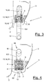
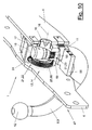
- Figures 1 to 4 show a hitch (1) at the rear (3) of a vehicle (2) in a broken side view and in different positions of movement.
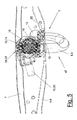
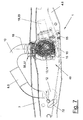
- Figure 5 to 7 show the corresponding movement positions in Rear view from the back.
- the hitch (1) is the towing vehicle (2) assigned and is in a cavity of the vehicle rear (3) housed hidden, which at the bottom of a Rear opening (52) has.
- the hitch (1) has a preferably double or substantially U-shaped curved drawbar (8), which at the free high projecting end of the rod neck (9) has a suitable pulling head (12), e.g. wearing a standard ball head.
- the pull rod (8) exists preferably of metal, e.g. Steel or light metal. Of the Rod neck (9) is after a first curvature (10) in an obliquely sloping back straight section and then over another bend (10) into another Straight and vertical rod end (11) over.
- Figures 1 and 5 show this, the operating position (47), in the extended drawbar (8) the above Positions and alignments occupies and with their Ball head (12) ready for coupling with distance in front of the Rear skirt (3) is positioned.
- Figures 4 and 7 show the retracted rest position (48) of the drawbar (8).
- the ball bar (8) is preferably gimbal biaxial stored and is powered by a mechanical and preferably motorized drive (13) moves.
- the Drive motor (20) is preferably as an electric motor, designed in particular as a geared motor. He is over a suitable cable tow from the power supply of the Towing vehicle (2) with operating voltage and control signals provided.
- the hitch (1) further has a not shown control, with corresponding Controls for positioning in towing vehicle (2) equipped or possibly already on the vehicle side existing controls is connected.
- the Towing device (1) can thereby between their End positions (47,48) are moved back and forth, wherein Indicator lights or the like the correct function or show malfunctions.
- the control can be from the Vehicle interior, but also from the outside over a preferably wireless remote control by radio, Infrared or the like. Be operated.
- the cable tow can also be connected to a power outlet on the Pull rod (8) be connected and her the required Operating voltage and signal or control voltages forward.
- About the central control of Towing device (1) can in this case the currents mentioned or voltages at the socket (43) at rest (48) switched off and switched to operating position (47) become.
- the hitch (1) has a following closer described locking device (56), with the Drawbar (8) in at least one of its end positions, preferably in the operating position (47) Locking elements (58,59) positively locked and can be held. The drive (13) is thereby relieved.
- the rear rod end (11) is by means of a Rotary bearings (17) in a housing (19) about a central Rotary axis (18) rotatably mounted.
- the housing (19) is in turn via a transverse to the axis of rotation (18) lying Swivel axis (16) and an associated pivot bearing (15) a cross member (4) in the rear region (3) of the towing vehicle (2) stored.
- the rotational axes (16,18) are preferably in the manner of a cardanic storage aligned at right angles to each other and intersect.
- the pivot axis (16) preferably extends along the longitudinal axis of the towing vehicle.
- the cross member (4) can Be part of the hitch (1). He can but also be provided by the towing vehicle on site.
- FIGS. 1 to 4 and 5 to 6 show the Pull rod (8) thanks to the cardan bearing from the in Figures 1 and 5 shown extended operating position (47) in a retracted illustrated in Figures 4 and 7 Rest position (48) are moved.
- FIGS. 2 and 3 and 6 show the assumed intermediate positions.
- the Pull rod (8) leads to a superimposed and at least partially simultaneous rotational movement around both rotary axes (16,18) off.
- the pull rod (8) turns around its axis of rotation (18) at the rod end (11) to preferably 90 °, whereby they are about the pivotal movement of the housing (19). by a larger angle of e.g. 180 ° to 190 ° around the Swivel axis (16) is moved.
- the doubly curved tie rod (8) moves with her ball head (12) in a little sweeping path under the lower end of the rear skirt (3) and can then end up in the cavity (7) behind the rear apron (3) dip.
- At rest (48) is in this preferred embodiment of the pull rod (8) and one attached to the pull rod (8) and mitbewegten Outlet from the outside nothing to see.
- the parts are completely hidden behind the rear apron (3). in this connection takes the pull rod (8) in the rest position (48) a transversely to the vehicle longitudinal axis aligned position, in the she points with their curvatures (10) upwards.
- FIG. (4) illustrates, has the hitch (1) at least one seal (51) attached to the underside of the cross member (4) and / or on the rear apron (3) is arranged.
- the seal (51) can be the following further explained free space (7) at least in the Rest position (48) of the pull rod (8) down close. It can e.g. from a lip seal or from a connected to the pull rod (8) and at the Rear opening reciprocable slide or like other construction.
- the mechanical drive (13) has a device (14) for generating the superimposed rotational movement of Pull rod (8) around the two rotary axes (16,18).
- the device (14) is preferably a multi-part Gear (21) is formed, which consists of a Swivel gear (22) and a rotary gear (23) consists.
- the cross member (4) has in the preferably middle region, where usually the hitch (1) on towing vehicle (2) is positioned, an elongated free space (7), in which the drawbar (8) with the housing (19) and the socket can move, the housing (19) pivotable on the walls surrounding the free space (7) can be stored.
- the cross member (4) exists for this purpose for example, two transverse to the vehicle longitudinal axis aligned support tubes (5) or other suitable Carrier elements in the center of the vehicle under Formation of the free space (7) in the vehicle longitudinal direction are distanced from each other laterally.
- the free space (7) is bounded laterally by two parallel support plates (6), the end attached to the two support tubes (5), e.g. are welded.
- the support plates (6) form in the Center each a pivot bearing part (39), which is e.g. when Bearing eye is formed by the second, with the Housing (19) connected pin-like pivot bearing parts (38) rotatable and optionally in conjunction with the Locking device (56) slidably mounted and is guided.
- the device (14) for generating the superimposed Rotational motions are preferably as mentioned two-piece gear (21) formed, which is the rotatory axes (16,18) coupled.
- the one Transmission part is designed as a pivoting gear (22) and acts on the pivot axis (16).
- the other Transmission part is designed as a rotary gear (23) and acts on the axis of rotation (18).
- the gear parts (22,23) are coupled together in terms of movement, wherein preferably the rotational movement about the axis of rotation (18) of the larger pivotal movement in this embodiment is derived around the pivot axis (16).
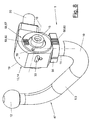
- FIG. 8 is the rotational driving Drive motor (20) end flanged to the housing (19). It is shown in FIG. 10 and 11 Drive element (24) of the pivoting gear (22) connected, which e.g. is designed as a worm shaft and with a relatively stationary support member (25) into engagement stands.
- Gear (68) preferably a worm wheel
- FIGS. 10 and 11 Gear (68), preferably a worm wheel, on a Support ring (31) temporarily stationary at the adjacent Support plate (6) is attached.
- the gear (68) and the Support ring (31) are concentric with the pivot axis (16) arranged and have inside a circular Through opening for the bearing pin (38) of the Swivel bearing (15) on the housing (19).
- Gear (68) on the vehicle rear (3) facing side arranged the cross member (4) Preferably that is Gear (68) on the vehicle rear (3) facing side arranged the cross member (4).
- the arrangement can alternatively also be the other way around.
- the gear (68) is also part of Locking device (56). During the normal Pivoting movements of the rack (8) between their End positions (47,48) is the gear (68) stationary and stored relatively stationary on the support ring (31) and held. The tangentially engaged worm shaft (24) meshes with the externally toothed gear (68). By a Rotation of the worm shaft (24) moves the Drive motor (20) with the flanged housing (19) in the desired direction of rotation about the pivot axis (16) after left or right.
- the rotary gear (23) is arranged, which one of the rod end (11) on the circumference arranged ring gear (53) and one to the pivot axis (16) concentric dental arch (54) at the front of the relatively stationary support ring (31).
- These Arrangement is apparent from Figures 12 and 13.
- For education of the pivot bearing (17) are on the rod end (11) on both sides of the Sprocket (53) two pivot bearing surfaces (37) available. Between these, a circumferential securing groove (35) to form an axial securing device (33).
- the housing (19) has in the area of Dental arch (54) has a circular arc-shaped opening through which the dental arch (54) and engage with the sprocket (53) can comb.
- the Housing (19) with the therein mounted tie rod (8) to the Swivel axis (16) pivots the ring gear (53) rolls the dental arch (54), whereby the rack (8) to the Turning axis (18) is rotated.
- the dental arch (54) and the Sprocket (53) can be a suitable and on the desired superposition of rotary and pivoting movement have coordinated arrangement and training of the teeth. This concerns on the one hand the translation of the gearing and on the other hand, the arrangement and length of Dental arch (54).
- the locking device (56) is present.
- FIGS. 8 to 13 and FIGS. 14, 15 are two different embodiments of Locking device (56) and the Transfer device (57) shown.
- the locking is the first rigid connection between the gear (68) and the Support ring (31) dissolved, whereby the gear (68) itself itself about the pivot axis (16) can rotate.
- These Rotational motion is used to generate the translatory Locking movement used.
- the locking elements are (58,59) preferably designed as toothed racks (60,61) and pointing to the front of the vehicle Cross member side arranged.
- the racks (60,61) are by a translational displacement movement of the Pull rod (8) and the housing (19) mutually in brought positive engagement.
- Housing (19) as well as the rod collar (36) horizontally extending racks (60) present with corresponding counter-toothed strips (61) on the adjacent Support plate (6) engage.
- the toothed racks (60, 61) have several teeth with a preferably trapezoidal Cross section, the support by large wings from high to the drawbar (8), especially the Allow ball head (12), acting shear forces.
- the locking device (56) respectively in the starting position at the beginning of the Locking movement shown in the Bar elements (58,59) are distanced and not yet mesh.
- the gear (68) is at least partially from the housing (19) surrounded and is there on both sides via appropriate Guiding means (69) out.
- the gear (68) can As a result, in its screw movement relative to the in Turn stop position pivot-resistant housing (19), wherein it the housing (19) via the guides (69) at its translational displacement movement takes along.
- the Sliding bearing of the pivot bearing (15) can here the Housing (19) together with the drawbar (8) along the Pivot axis (16) to the opposite support plate (6) be moved, causing the arranged there Locking elements (58,59) engage.
- the housing (19) may have one or more anti-rotation devices exhibit. For example, one is next to the toothed racks (60) arranged and parallel to the axis (16) aligned locking pin (70) present in the Lock in a corresponding receiving opening on the Support plate (6) engages.
- the lock in the Operating position (47) should be solved again, prevents the turnstile (70) turning the housing (19) about the pivot axis (16), so that the drive motor (20) first by means of the worm shaft (24) the gear (68) turns back into the stop position in the opposite direction and at the same time the housing (19) with the pull rod (8) the locking position moves.
- the locking pin (70) This is longer than the tooth height of the toothed racks (60,61) and also acts as a turnstile after loosening the Gearing contact.
- another can also Blocking element e.g. a spring-loaded ball catch or the like between the housing (19) and the lock-side support plate (6) may be present.
- Locking elements (58, 59) as a blocking ball (62, 63, 64) formed, with its translational Locking movement through concentric curved Slotted guides (71) on the gear (68) is effected which increases in the direction of rotation obliquely outward Guide surfaces for displacing the locking balls (62, 63, 64) exhibit.
- the gear (68) does not need in this case own translational displacement movement to execute. It is therefore preferably only rotatable and non-displaceable the support ring (31) attached to the support plate (6) stored.
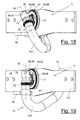
- FIG. 14 shows the locking device (56) at the beginning the locking movement.
- FIG. 15 shows the end position.
- the rod end (11) At the rod end (11) are one or more recessed Receivers, preferably ball receivers (65), arranged, into which the respectively associated blocking ball (62, 63) can dive.
- the ball mounts (65) are in Cross-section circular and provide a side guide for the locking balls (62,63). They are also regarding the Rotary axis (18) in different angular positions and In addition, in different axial heights at Rod end (11) arranged. Figure 22 shows this Arrangement with different weights for the visible and the hidden side. These different angular positions and altitudes are on the position of the openings (83) matched to the housing (19) and correspond to one or both end positions (47,48), i.e. Rest and / or operating position of the drawbar (8).
- Figures 16 to 25 show a third variant of the drive (13) and the transmission (21) and the Locking device (56).
- the rotary gear (23) is in the third variant of one on the support-fixed support ring (31) frontally attached annular ring gear (81) and a Toothed ring (73) formed on the rod end (11). Of the Toothed ring (73) is on the rod end (11) to the Rotary axis (18) rotatably mounted and in the axial direction guided.
- the rotation is controlled by a Locking element (74), which preferably as a ball is formed in a ball stud (75) on the toothed ring (73).
- the ball (74) can only radial displacements with respect to the axis of rotation (18) To run.
- the ball (74) acts with a latching opening (76) at the rod end (11) together, which engages with the Ball (74) blocks the rotational movement of the toothed ring (73) and a rotational connection between the drawbar (8) and the toothed ring (73) produces.
- the angular position of the Latching opening (76) relative to the axis of rotation (18) and the Center plane of the curved drawbar (8) is chosen that the rotation when pivoting the drawbar (8) after approx. 90 ° swivel movement and in an operating position takes place according to Figure 3, 6 and 17.
- the latching opening (76) can flattened opening edges (77) to the inlet and outlet of the ball (74) facilitate.
- Figure 22 shows this arrangement.
- (19) is an annular ring surrounding the toothed ring (73) Recess exists, which is a step or a stop may own, in addition to the rotational position the ball (74) in the latching opening (76) forces and in further course of the pivoting and rotating movement holds there.
- the rod end (11) can in the region of the toothed ring (73) have an annular groove, with the size and the Diameter of the arrangement can be reduced. On The annular groove can also be dispensed with.
- FIG. 23 shows the housing (19), which at the third Variant is slightly different than in the other Embodiments.
- Figures 24 and 25 show the Assembly situation without motor (20).
- the housing (19) has at the bottom of its guide part (40), which for the inside guide of the gear (68) is provided, an opening (82) for the inner toothed ring (73), the penetration for connection with the outside Sprocket (81) allows, which in the view of FIG. 23 is in the viewing direction in front of the guide part (40).
- the housing (19) also has on the guide part (40) two or more openings (83) for the following closer explained locking balls (78).
- the bearing pin (38) engages by the stationary support ring (31), which at the same time the Bearing eye forms. On the other side is the other one Bearing journals (38) mounted directly in the cross member (4).
- the Locking device (56) also able to Pull rod (8) in the retracted rest position (48) lock.
- This is also done by means of a bolt or Blocking elements (78), preferably a blocking ball, the transversely movable in an opening (83) of the housing (19) is guided.
- the locking ball (78) engages in the Rest position (48) in a form-locking manner in a latching opening (79) on the pull rod (8), in particular on the rod end (11).
- the blocking ball engagement is effected by a Slotted guide (80) on the gear (68) by a Gear rotation is actuated and the locking ball (78) in the latching opening (79) pushes.
- the gear rotation is similar to the locking in the operating position (47) by a further running of the drive motor (20) and reaches the worm shaft (24) when the pull rod (8) in the rest position on the stop shown in Figure 7 (72) starts.
- the detent opening (79) can be slightly oversized have, so the latch with slight play he follows.
- the locking ball (78) can have a dual function and in the operating position (47) with the ball seat (65) in Engage, which with angular displacement on the same Height with the latching opening (79) is located.
- the hitch (19) may alternatively or in addition to the electrical outlet (43) one with the Drawbar (8) connected to current transformer (84), which is shown schematically in Figure 22.
- Current transformer (84) conducts power and signal currents from the towing vehicle via the hitch (1) over the attached trailer hitch (89) to the trailer. in this connection is in or on the pull rod (8) at least one line (87) for power and signal currents used at the Traction vehicle side to a power supply and a Decoder (85) is connected.
- the power transmission takes place with attached trailer hitch (89) by two or more contacts (88,89) in the ball head (12) and in the Coupling socket.
- the contacts (88,89) can be sprung Be sure to make contact among all To produce operating conditions.
- the trailer side Contact (89) is also via a line (87) with the Power consumers of the trailer e.g. of the Trailer lighting, the turn signals or the like connected.
- the signal line is on the trailer side to an encoder (86) connected.
- relevant Information e.g. the function of lighting, one Turn signal or the like in corresponding signals converted, either by separate means or in Superposition of the power currents to the decoder (85) be fed to where they are decrypted and for further Recovery, e.g. Output of an alarm message or the like the towing vehicle will be forwarded.
- toothed racks (60,61) can be any other suitable form-fitting Bar elements (58, 59) may be used, e.g. Pins or Feather keys, the translational displacement movement of the housing (19) and the pull rod (8) into one another to grab.
- tie rods (8) which only um a single axis can be pivoted the gear (68) be circumferentially arranged on the rod end (11), wherein the translational locking movement along the Rotary axis (18) is executed.
- the three shown and described embodiments can be hereby apply accordingly.
Landscapes
- Engineering & Computer Science (AREA)
- Transportation (AREA)
- Mechanical Engineering (AREA)
- Agricultural Machines (AREA)
- Gear Transmission (AREA)
- Handcart (AREA)
- Vehicle Cleaning, Maintenance, Repair, Refitting, And Outriggers (AREA)
Abstract
Description
Die beanspruchte Verriegelungsvorrichtung hat den Vorteil, dass formschlüssige Riegelelemente in der Verriegelungsstellung direkt an der Zugstange angreifen und diese in ein oder beiden Endstellungen festhalten. Hierdurch ist die Zugstange insbesondere in der ausgefahrenen Betriebsstellung höher belastbar, wobei die Verriegelungsvorrichtung große an der Zugstange angreifende Querkräfte aufnehmen und abstützen kann.
- Figur 1 bis 4:
- eine Anhängevorrichtung mit Teilen des Fahrzeughecks in verschiedenen Bewegungsstadien zwischen der ausgefahrenen Betriebsstellung und der eingezogenen Ruhestellung in aufgebrochener Seitenansicht,
- Figur 5 bis 7:
- die Anhängevorrichtung mit den verschiedenen Bewegungsstellungen von Figur 1 bis 4 aus der Heckansicht,
- Figur 8:
- eine perspektivische Ansicht der Zugstange mit einem motorischen Antrieb und einer Verriegelungsvorrichtung,
- Figur 9:
- eine teilweise aufgebrochene perspektivische Darstellung der Anhängevorrichtung von Figur 8 in der Einbausituation am Fahrzeugheck,
- Figur 10:
- eine noch stärker aufgebrochene Darstellung der Anhängevorrichtung gemäß Figur 9,
- Figur 11:
- eine andere aufgebrochene perspektivische Detailansicht der Anhängevorrichtung gemäß Figur 10,
- Figur 12 und 13:
- zwei weitere noch stärker aufgebrochene und abstrahierte perspektivische Darstellungen der Anhängevorrichtung von Figur 9 und 10,
- Figur 14 und 15:
- eine Variante der Verriegelungsvorrichtung in zwei Betriebsstellungen und unterschiedlich großen Darstellungen,
- Figur 16 bis 19:
- aufgebrochene perspektivische Darstellungen einer weiteren Variante des Antriebs der Anhängevorrichtung in verschiedenen Bewegungsstellungen,
- Figur 20:
- eine vergrößerte perspektivische Detaildarstellung des Stangenendes in verriegelter Ruhestellung
- Figur 21:
- eine vergrößerte perspektivische Detaildarstellung eines Zahnrings,
- Figur 22:
- eine Seitenansicht der Zugstange von Figur 16 bis 20 mit Stromübertrager,
- Figur 23:
- eine perspektivische Seitenansicht des Gehäuses zur Antriebsvariante von Figur 16 bis 20 und
- Figur 24 bis 25:
- teilweise aufgebrochene perspektivische Darstellungen des Antriebs in der Zusammenbausituation.
- 1
- Anhängevorrichtung
- 2
- Zugfahrzeug
- 3
- Heckteil, Heckschürze
- 4
- Querträger
- 5
- Tragrohr
- 6
- Tragplatte
- 7
- Freiraum
- 8
- Zugstange
- 9
- Stangenhals
- 10
- Krümmung
- 11
- Stangenende
- 12
- Zugkopf, Kugelkopf
- 13
- Antrieb
- 14
- Einrichtung für überlagerte Rotationsbewegung
- 15
- Schwenklager
- 16
- Schwenkachse
- 17
- Drehlager
- 18
- Drehachse
- 19
- Gehäuse
- 20
- Antriebsmotor
- 21
- Getriebe
- 22
- Getriebeteil, Schwenkgetriebe
- 23
- Getriebeteil, Drehgetriebe
- 24
- Antriebselement, Schneckenwelle
- 25 26 27 28 29 30
- Abstützelement, Zahnkranz relativ ortsfest
- 31 32
- Stützring
- 33 34
- Axialsicherung
- 35
- Sicherungsnut
- 36
- Stangenbund
- 37
- Drehlagerfläche Zugstange
- 38
- Schenklagerteil, Lagerzapfen Gehäuse
- 39
- Schenklagerteil, Lagerauge Querträger
- 40 41 42 43 44 45 46
- Führungsteil Gehäuse
- 47
- Endstellung, Betriebsstellung
- 48 49 50
- Endstellung, Ruhestellung
- 51
- Dichtung
- 52
- Hecköffnung
- 53
- Zahnkranz am Stangenende
- 54
- Zahnbogen
- 55
- Anschlag für Zugstange
- 56
- Verriegelungsvorrichtung
- 57
- Übertragungsvorrichtung
- 58
- Riegelelement
- 59
- Riegelelement
- 60
- Zahnleiste
- 61
- Zahnleiste
- 62
- Sperrkugel
- 63
- Sperrkugel
- 64
- Sperrkugel
- 65
- Kugelaufnahme
- 66
- Bewegungsgewinde
- 67
- Gewindehülse
- 68
- Rad, Zahnrad, Schneckenrad
- 69
- Führung für Zahnrad
- 70
- Drehsperre, Sperrstift
- 71
- Kulissenführung
- 72
- Anschlag für Kugelkopf
- 73
- Zahnring
- 74
- Arretierelement, Kugel
- 75
- Kugelnest am Zahnring
- 76
- Rastöffnung an Zugstange, Kugelaufnahme
- 77
- Öffnungsflanke
- 78
- Sperrelement, Sperrkugel
- 79
- Rastöffnung an Zugstange, Kugelaufnahme
- 80
- Kulissenführung für Sperrkugel
- 81
- Zahnkranz
- 82
- Öffnung für Zahnring
- 83
- Öffnung für Kugel
- 84
- Stromübertrager
- 85
- Decoder
- 86
- Encoder
- 87
- Leitung
- 88
- Kontakt
- 89
- Kontakt
- 90
- Anhängerkupplung
Claims (17)
- Anhängevorrichtung für Zugfahrzeuge (2), bestehend aus einer Zugstange (8), die um mindestens eine rotatorische Achse (16,18) schwenkbar gelagert ist und von einem mechanischen Antrieb (13) zwischen einer ausgefahrenen Betriebsstellung (47) und einer eingefahrenen Ruhestellung (48) am Zugfahrzeuge (2) bewegbar ist, wobei die Anhängevorrichtung (1) eine automatische und vom mechanischen Antrieb (13) betätigbare Verriegelungsvorrichtung (56) aufweist, dadurch gekennzeichnet, dass die Verriegelungsvorrichtung (56) eine Übertragungsvorrichtung (57) aufweist zum Umsetzen der drehenden Antriebsbewegung in eine translatorische Verriegelungsbewegung für die Betätigung von formschlüssigen Riegelelementen (58,59), die an der Zugstange (8) angreifen.
- Anhängevorrichtung nach Anspruch 1, dadurch gekennzeichnet, dass die Übertragungsvorrichtung (57) ein mit dem mechanischen Antrieb (13) verbundenes Rad (68) mit mindestens einer Kulissenführung (71,80) aufweist, welches am Ende der Zugstangenbewegung Riegelelemente (58,59) verschiebt und in sperrenden Eingriff mit der Zugstange (8) bringt.
- Anhängevorrichtung nach Anspruch 2, dadurch gekennzeichnet, dass das Rad als Zahnrad (68) ausgebildet ist.
- Anhängevorrichtung nach Anspruch 1, dadurch gekennzeichnet, dass die Übertragungsvorrichtung (57) ein mit dem mechanischen Antrieb (13) verbundenes Zahnrad (68) mit einem Bewegungsgewinde (66) aufweist, welches am Ende der Zugstangenschwenkbewegung die Zugstange (8) translatorisch verschiebt und die Riegelelemente (58,59) in Eingriff bringt.
- Anhängevorrichtung nach einem der vorhergehenden Ansprüche, dadurch gekennzeichnet, dass die Riegelelemente (58,59) als Zahnleisten (60,61) oder als Sperrkugeln (62,63,64,78) mit Kugelaufnahmen (65,78,79) und Kugelführungen ausgebildet sind.
- Anhängevorrichtung nach einem der vorhergehenden Ansprüche, dadurch gekennzeichnet, dass ein Teil der Riegelelemente (58,59) relativ ortsfest an der Anhängevorrichtung (1) abstützbar ist.
- Anhängevorrichtung nach einem der vorhergehenden Ansprüche, dadurch gekennzeichnet, dass die Riegelelemente (58,62,63) an mindestens einer Öffnung (83) im Gehäuse (19) des Antriebs (13) querbeweglich geführt sind.
- Anhängevorrichtung nach einem der vorhergehenden Ansprüche, dadurch gekennzeichnet, dass am Stangenende (11) ein oder mehrere Aufnahmen (65) für die Riegelelemente (58) angeordnet sind.
- Anhängevorrichtung nach Anspruch 8, dadurch gekennzeichnet, dass die Aufnahmen (65) als Vertiefungen ausgebildet und in unterschiedlichen umfangseitigen Winkelstellungen und Höhenlagen am Stangenende (11) angeordnet sind, welche in Abstimmung mit der Lage der Öffnungen (83) zumindest einer Endstellung (47,48) der Zugstange (8) entsprechen.
- Anhängevorrichtung nach einem der vorhergehenden Ansprüche, dadurch gekennzeichnet, dass auf der anderen Seite des Rads (68) ein oder mehrere Riegelelemente (58,64) angeordnet sind, die über eine Kulissenführung (71) mit einer relativ ortsfesten Aufnahme in Eingriff bringbar sind.
- Anhängevorrichtung nach einem der vorhergehenden Ansprüche, dadurch gekennzeichnet, dass die Zugstange (8) um mindestens zwei rotatorische Achse (16,18) drehbar gelagert ist, wobei der Antrieb (13) eine Einrichtung (14) zur Erzeugung einer überlagerten Rotationsbewegung der Zugstange (8) um beide Achsen (16,18) aufweist.
- Anhängevorrichtung nach einem der vorhergehenden Ansprüche, dadurch gekennzeichnet, dass die Zugstange (8) eine kardanische Lagerung mit einem Schwenklager (15) und einem Drehlager (17) mit sich kreuzenden rotatorischen Achsen (16,18) aufweist.
- Anhängevorrichtung nach einem der vorhergehenden Ansprüche, dadurch gekennzeichnet, dass die Einrichtung zur Erzeugung (14) der überlagerten Rotationsbewegung als ein die Schwenkachse (16) und die Drehachse (18) koppelndes Getriebe (21) ausgebildet ist, wobei die Drehbewegung der Zugstange (8) um die Drehachse (18) von der Schwenkbewegung der Zugstange (8) oder des Gehäuses (19) abgeleitet ist und das Getriebe (21) mehrere gekoppelte Getriebeteile (22,23) und einen gemeinsamen Antriebsmotor (20) aufweist.
- Anhängevorrichtung nach Anspruch 13, dadurch gekennzeichnet, dass der mitbewegte Antriebsmotor (20) auf ein erstes Getriebeteil (22) einwirkt, welches als Schwenkgetriebe ausgebildet ist und ein mit dem Antriebsmotor (20) verbundenes Antriebselement (24), vorzugsweise eine Schneckenwelle, und ein damit im Eingriff stehendes externes relativ stationäres Abstützelement (25) aufweist, welches als umfangseitig verzahntes Zahnrad (68) ausgebildet ist.
- Anhängevorrichtung nach einem der vorhergehenden Ansprüche, dadurch gekennzeichnet, dass am oder im Gehäuse (19) ein Getriebe (21) oder Getriebeteil (23) angeordnet ist, welches die Schwenkbewegung des Gehäuses (19) in eine Drehbewegung der Zugstange (8) um die Drehachse (18) umsetzt, wobei das Getriebeteil (23) einen Zahnring (73) aufweist, der mit steuerbarem Drehschluss auf der Zugstange (8) um die Drehachse (18) rotierfähig gelagert ist und der mit einem relativ stationären Zahnkranz (81) kämmt.
- Anhängevorrichtung nach Anspruch 15, dadurch gekennzeichnet, dass der Zahnring (73) ein bewegliches Arretierelement (74) aufweist, welches mit einer Rastöffnung (76) an der Zugstange (8) zur Bildung der drehschlüssigen Verbindung zusammenwirkt.
- Anhängevorrichtung nach einem der vorhergehenden Ansprüche, dadurch gekennzeichnet, dass das Gehäuse (19) oder die Zugstange (8) eine bei der Verriegelung eingreifende Drehsperre (70) aufweisen.
Priority Applications (1)
| Application Number | Priority Date | Filing Date | Title |
|---|---|---|---|
| EP03018477A EP1407901B2 (de) | 2002-10-09 | 2003-08-14 | Anhängevorrichtung für Zugfahrzeuge |
Applications Claiming Priority (5)
| Application Number | Priority Date | Filing Date | Title |
|---|---|---|---|
| DE20215508U | 2002-10-09 | ||
| DE20215508U DE20215508U1 (de) | 2002-10-09 | 2002-10-09 | Anhängevorrichtung für Zugfahrzeuge |
| WOPCT/EP03/02008 | 2003-02-27 | ||
| PCT/EP2003/002008 WO2003072375A1 (de) | 2002-02-28 | 2003-02-27 | Schwenkbare anhängevorrichtung für zugfahrzeuge |
| EP03018477A EP1407901B2 (de) | 2002-10-09 | 2003-08-14 | Anhängevorrichtung für Zugfahrzeuge |
Publications (3)
| Publication Number | Publication Date |
|---|---|
| EP1407901A1 true EP1407901A1 (de) | 2004-04-14 |
| EP1407901B1 EP1407901B1 (de) | 2006-05-17 |
| EP1407901B2 EP1407901B2 (de) | 2012-10-03 |
Family
ID=31969820
Family Applications (1)
| Application Number | Title | Priority Date | Filing Date |
|---|---|---|---|
| EP03018477A Expired - Lifetime EP1407901B2 (de) | 2002-10-09 | 2003-08-14 | Anhängevorrichtung für Zugfahrzeuge |
Country Status (3)
| Country | Link |
|---|---|
| EP (1) | EP1407901B2 (de) |
| AT (1) | ATE326356T1 (de) |
| DE (1) | DE20215508U1 (de) |
Cited By (11)
| Publication number | Priority date | Publication date | Assignee | Title |
|---|---|---|---|---|
| EP1650059A1 (de) | 2004-10-25 | 2006-04-26 | Westfalia-Automotive GmbH & Co. KG | Anhängekupplung für Kraftfahrzeuge |
| EP1894752A1 (de) * | 2006-09-01 | 2008-03-05 | Brink International B.V. | Anhängerkupplung mit ein- und ausfahrbarem Zughaken |
| EP1902871A1 (de) * | 2006-09-18 | 2008-03-26 | WESTFALIA - Automotive GmbH | Anhängekupplung |
| DE202007007313U1 (de) * | 2007-04-28 | 2008-09-11 | Westfalia-Automotive Gmbh | Anhängerkupplung für Kraftfahrzeuge, insbesondere Personenkraftfahrzeuge |
| DE202007007314U1 (de) * | 2007-04-28 | 2008-09-11 | Westfalia-Automotive Gmbh | Anhängerkupplung für Kraftfahrzeuge, insbesondere Personenkraftfahrzeuge |
| DE202007007331U1 (de) * | 2007-04-28 | 2008-09-11 | Westfalia-Automotive Gmbh | Anhängerkupplung für Kraftfahrzeuge, insbesondere Personenkraftfahrzeuge |
| WO2020069936A3 (de) * | 2018-10-04 | 2020-05-28 | ACPS Automotive GmbH | Anhängekupplung |
| EP3441243B1 (de) | 2017-08-09 | 2020-07-01 | FAC Frank Abels Consulting & Technology GmbH | Motorisch verschwenkbare anhängekupplung |
| EP3708391A1 (de) * | 2019-03-12 | 2020-09-16 | Brink Towing Systems B.V. | Einziehbare anhängekuppungsanordnung |
| EP3868581A1 (de) * | 2011-12-09 | 2021-08-25 | WESTFALIA - Automotive GmbH | Steuergerät und anhängekupplung zur kommunikation mit einem bediengerät |
| WO2025016259A1 (zh) * | 2023-07-14 | 2025-01-23 | 浙江致优汽车科技有限公司 | 拖车联接器 |
Families Citing this family (5)
| Publication number | Priority date | Publication date | Assignee | Title |
|---|---|---|---|---|
| DE102006043430B4 (de) * | 2006-09-15 | 2009-12-03 | Jaeger Cartronix Gmbh | Verriegelung für eine Anhängerkupplung |
| DE102013007111A1 (de) * | 2013-04-21 | 2014-10-23 | Westfalia-Automotive Gmbh | Anhängekupplung |
| EP2796303B1 (de) * | 2013-04-21 | 2018-05-02 | WESTFALIA - Automotive GmbH | Anhängekupplung |
| DE102013007123A1 (de) * | 2013-04-21 | 2014-10-23 | Westfalia-Automotive Gmbh | Anhängekupplung |
| DE102013007115A1 (de) * | 2013-04-21 | 2014-10-23 | Westfalia-Automotive Gmbh | Anhängekupplung |
Citations (8)
| Publication number | Priority date | Publication date | Assignee | Title |
|---|---|---|---|---|
| US4499790A (en) * | 1982-05-22 | 1985-02-19 | Fa.Jungheinrich Unternehmensverwaltung Kg | Swivel head for industrial robots |
| US5584621A (en) * | 1995-06-13 | 1996-12-17 | Bertsche Engineering Corp. | Direct drive multiple axes rotary spindle head for milling machine |
| DE19521896A1 (de) | 1995-06-16 | 1997-01-30 | Oris Fahrzeugteile Riehle H | Anhängevorrichtung für insbesondere Personenkraftwagen |
| EP1009088A2 (de) * | 1998-12-09 | 2000-06-14 | Hella KG Hueck & Co. | Elektrischer Stellantrieb für ein Kraftfahrzeug |
| DE10004523A1 (de) * | 2000-02-02 | 2001-08-09 | Fac Frank Abels Consult & Tech | Anhängerkupplung |
| DE10023640A1 (de) * | 2000-05-13 | 2001-11-15 | Fac Frank Abels Consult & Tech | Anhängerkupplung |
| EP1225067A2 (de) * | 2001-01-23 | 2002-07-24 | FAC Frank Abels Consulting & Technology GmbH | Anhängerkupplung |
| DE10104186A1 (de) * | 2001-01-23 | 2002-07-25 | Fac Frank Abels Consult & Tech | Anhängerkupplung |
Family Cites Families (9)
| Publication number | Priority date | Publication date | Assignee | Title |
|---|---|---|---|---|
| DE19654867C2 (de) * | 1995-09-13 | 1998-01-22 | Cartron Fahrzeugteile Gmbh | Schwenkbare Anhängerkupplung für Kraftfahrzeuge |
| DE19612961A1 (de) * | 1996-04-01 | 1997-10-02 | Oris Fahrzeugteile Riehle H | Anhängekupplung |
| DE19848487A1 (de) * | 1998-10-21 | 2000-05-04 | Oris Fahrzeugteile Riehle H | Anhängekupplung |
| DE19858978C5 (de) * | 1998-12-19 | 2012-06-06 | Westfalia-Automotive Gmbh | Schwenkbare Anhängerkupplung für Kraftfahrzeuge |
| DE19859961C2 (de) * | 1998-12-29 | 2003-07-03 | Westfalia Automotive Gmbh & Co | Anhängerkupplung mit einem schwenkbaren Kugelhals |
| DE19902355A1 (de) † | 1999-01-21 | 2000-08-03 | Oris Fahrzeugteile Riehle H | Anhängekupplung |
| DE19944082A1 (de) * | 1999-09-15 | 2001-03-29 | Jaeger Cartronix Gmbh | Schwenkbare Anhängerkupplung mit selbsttätiger Verriegelung |
| DE19944264A1 (de) † | 1999-09-15 | 2001-03-22 | Jaeger Cartronix Gmbh | Anhängerkupplung mit axialem Verfahrweg |
| DE10017013A1 (de) † | 2000-04-05 | 2001-10-18 | Oris Fahrzeugteile Riehle H | Anhängekupplung |
-
2002
- 2002-10-09 DE DE20215508U patent/DE20215508U1/de not_active Expired - Lifetime
-
2003
- 2003-08-14 AT AT03018477T patent/ATE326356T1/de not_active IP Right Cessation
- 2003-08-14 EP EP03018477A patent/EP1407901B2/de not_active Expired - Lifetime
Patent Citations (8)
| Publication number | Priority date | Publication date | Assignee | Title |
|---|---|---|---|---|
| US4499790A (en) * | 1982-05-22 | 1985-02-19 | Fa.Jungheinrich Unternehmensverwaltung Kg | Swivel head for industrial robots |
| US5584621A (en) * | 1995-06-13 | 1996-12-17 | Bertsche Engineering Corp. | Direct drive multiple axes rotary spindle head for milling machine |
| DE19521896A1 (de) | 1995-06-16 | 1997-01-30 | Oris Fahrzeugteile Riehle H | Anhängevorrichtung für insbesondere Personenkraftwagen |
| EP1009088A2 (de) * | 1998-12-09 | 2000-06-14 | Hella KG Hueck & Co. | Elektrischer Stellantrieb für ein Kraftfahrzeug |
| DE10004523A1 (de) * | 2000-02-02 | 2001-08-09 | Fac Frank Abels Consult & Tech | Anhängerkupplung |
| DE10023640A1 (de) * | 2000-05-13 | 2001-11-15 | Fac Frank Abels Consult & Tech | Anhängerkupplung |
| EP1225067A2 (de) * | 2001-01-23 | 2002-07-24 | FAC Frank Abels Consulting & Technology GmbH | Anhängerkupplung |
| DE10104186A1 (de) * | 2001-01-23 | 2002-07-25 | Fac Frank Abels Consult & Tech | Anhängerkupplung |
Cited By (15)
| Publication number | Priority date | Publication date | Assignee | Title |
|---|---|---|---|---|
| EP1650059A1 (de) | 2004-10-25 | 2006-04-26 | Westfalia-Automotive GmbH & Co. KG | Anhängekupplung für Kraftfahrzeuge |
| DE102004051976A1 (de) * | 2004-10-25 | 2006-04-27 | Westfalia-Automotive Gmbh & Co. Kg | Anhängerkupplung für Kraftfahrzeuge |
| EP1894752A1 (de) * | 2006-09-01 | 2008-03-05 | Brink International B.V. | Anhängerkupplung mit ein- und ausfahrbarem Zughaken |
| EP1902871A1 (de) * | 2006-09-18 | 2008-03-26 | WESTFALIA - Automotive GmbH | Anhängekupplung |
| DE202007007331U1 (de) * | 2007-04-28 | 2008-09-11 | Westfalia-Automotive Gmbh | Anhängerkupplung für Kraftfahrzeuge, insbesondere Personenkraftfahrzeuge |
| DE202007007314U1 (de) * | 2007-04-28 | 2008-09-11 | Westfalia-Automotive Gmbh | Anhängerkupplung für Kraftfahrzeuge, insbesondere Personenkraftfahrzeuge |
| DE202007007313U1 (de) * | 2007-04-28 | 2008-09-11 | Westfalia-Automotive Gmbh | Anhängerkupplung für Kraftfahrzeuge, insbesondere Personenkraftfahrzeuge |
| DE102008018822B4 (de) * | 2007-04-28 | 2013-11-14 | Westfalia-Automotive Gmbh | Anhängerkupplung für Kraftfahrzeuge, insbesondere Personenkraftfahrzeuge |
| EP3868581A1 (de) * | 2011-12-09 | 2021-08-25 | WESTFALIA - Automotive GmbH | Steuergerät und anhängekupplung zur kommunikation mit einem bediengerät |
| EP3441243B1 (de) | 2017-08-09 | 2020-07-01 | FAC Frank Abels Consulting & Technology GmbH | Motorisch verschwenkbare anhängekupplung |
| EP3441243B2 (de) † | 2017-08-09 | 2023-08-09 | FAC Frank Abels Consulting & Technology GmbH | Motorisch verschwenkbare anhängekupplung |
| WO2020069936A3 (de) * | 2018-10-04 | 2020-05-28 | ACPS Automotive GmbH | Anhängekupplung |
| EP3708391A1 (de) * | 2019-03-12 | 2020-09-16 | Brink Towing Systems B.V. | Einziehbare anhängekuppungsanordnung |
| EP4056390A1 (de) * | 2019-03-12 | 2022-09-14 | Brink Towing Systems B.V. | Einziehbare schlepphakenanordnung |
| WO2025016259A1 (zh) * | 2023-07-14 | 2025-01-23 | 浙江致优汽车科技有限公司 | 拖车联接器 |
Also Published As
| Publication number | Publication date |
|---|---|
| ATE326356T1 (de) | 2006-06-15 |
| EP1407901B1 (de) | 2006-05-17 |
| EP1407901B2 (de) | 2012-10-03 |
| DE20215508U1 (de) | 2004-04-01 |
Similar Documents
| Publication | Publication Date | Title |
|---|---|---|
| EP1478528B1 (de) | Schwenkbare anhängevorrichtung für zugfahrzeuge | |
| EP3829956B1 (de) | Verstellantrieb für eine lenksäule und lenksäule für ein kraftfahrzeug | |
| EP1880879B1 (de) | Schwenkbare Anhängevorrichtung für Zugfahrzeuge | |
| EP1407901B1 (de) | Anhängevorrichtung für Zugfahrzeuge | |
| DE69810751T2 (de) | Motorgetriebenes ausschiebesystem mit lösbarer bremse | |
| EP1389544A1 (de) | Fensterrollo mit Kupplungsmechanismus | |
| EP2088008A1 (de) | Anhängerkupplung für Kraftfahrzeuge | |
| DE3804117A1 (de) | Mechanische lineareinheit | |
| DE202005002585U1 (de) | Elektromotorischer Linearantrieb | |
| DE4436326C1 (de) | Schloß, insbesondere zum Verriegeln der Lenkspindel oder der Zahnstange des Lenkgetriebes oder der Ausgangswelle des Antriebsgetriebes eines Kraftfahrzeugs | |
| EP1650059B1 (de) | Anhängekupplung für Kraftfahrzeuge | |
| EP2428380A2 (de) | Verschlusseinrichtung | |
| EP0941889A2 (de) | Ausziehvorrichtung | |
| DE10048224A1 (de) | Verriegelungseinheit für einen Teleskopausleger eines Krans | |
| EP2520746B1 (de) | Elektrisch betätigbares Schloss | |
| DE9112079U1 (de) | Betätigungsgetriebe für längsverschiebbare Treibstangen an Beschlägen von Fenstern und Türen o.dgl. | |
| EP1544003B1 (de) | Anhängekupplung für Personenkraftfahrzeuge | |
| EP1002923A2 (de) | Vorrichtung zum Öffnen und Verschliessen einer Öffnung in einer Wandung mittels einer Schiebetür | |
| DE102019128563A1 (de) | Elektromechanischer Parksperrenaktuator | |
| EP0671530B2 (de) | Beschlag für ein Fenster oder eine Türe | |
| DE102005044778A1 (de) | Längseinsteller für einen Fahrzeugsitz | |
| EP2143859B1 (de) | Verriegelungsvorrichtung | |
| EP3800315A1 (de) | Gebäudeöffnung mit einer einrichtung zum öffnen und schliessen sowie ver- und entriegeln von gebäudeöffnungen | |
| DE3018633A1 (de) | Elektrobohrhammer mit abschaltbarem bohrantrieb | |
| DE19858980C5 (de) | Fahrzeugsitz, insbesondere Kraftfahrzeugsitz, mit einer Einstellvorrichtung |
Legal Events
| Date | Code | Title | Description |
|---|---|---|---|
| PUAI | Public reference made under article 153(3) epc to a published international application that has entered the european phase |
Free format text: ORIGINAL CODE: 0009012 |
|
| AK | Designated contracting states |
Kind code of ref document: A1 Designated state(s): AT BE BG CH CY CZ DE DK EE ES FI FR GB GR HU IE IT LI LU MC NL PT RO SE SI SK TR |
|
| AX | Request for extension of the european patent |
Extension state: AL LT LV MK |
|
| 17P | Request for examination filed |
Effective date: 20040813 |
|
| AKX | Designation fees paid |
Designated state(s): AT BE BG CH CY CZ DE DK EE ES FI FR GB GR HU IE IT LI LU MC NL PT RO SE SI SK TR |
|
| GRAP | Despatch of communication of intention to grant a patent |
Free format text: ORIGINAL CODE: EPIDOSNIGR1 |
|
| GRAS | Grant fee paid |
Free format text: ORIGINAL CODE: EPIDOSNIGR3 |
|
| GRAA | (expected) grant |
Free format text: ORIGINAL CODE: 0009210 |
|
| AK | Designated contracting states |
Kind code of ref document: B1 Designated state(s): AT BE BG CH CY CZ DE DK EE ES FI FR GB GR HU IE IT LI LU MC NL PT RO SE SI SK TR |
|
| PG25 | Lapsed in a contracting state [announced via postgrant information from national office to epo] |
Ref country code: SK Free format text: LAPSE BECAUSE OF FAILURE TO SUBMIT A TRANSLATION OF THE DESCRIPTION OR TO PAY THE FEE WITHIN THE PRESCRIBED TIME-LIMIT Effective date: 20060517 Ref country code: SI Free format text: LAPSE BECAUSE OF FAILURE TO SUBMIT A TRANSLATION OF THE DESCRIPTION OR TO PAY THE FEE WITHIN THE PRESCRIBED TIME-LIMIT Effective date: 20060517 Ref country code: RO Free format text: LAPSE BECAUSE OF FAILURE TO SUBMIT A TRANSLATION OF THE DESCRIPTION OR TO PAY THE FEE WITHIN THE PRESCRIBED TIME-LIMIT Effective date: 20060517 Ref country code: IE Free format text: LAPSE BECAUSE OF FAILURE TO SUBMIT A TRANSLATION OF THE DESCRIPTION OR TO PAY THE FEE WITHIN THE PRESCRIBED TIME-LIMIT Effective date: 20060517 Ref country code: FI Free format text: LAPSE BECAUSE OF FAILURE TO SUBMIT A TRANSLATION OF THE DESCRIPTION OR TO PAY THE FEE WITHIN THE PRESCRIBED TIME-LIMIT Effective date: 20060517 Ref country code: CZ Free format text: LAPSE BECAUSE OF FAILURE TO SUBMIT A TRANSLATION OF THE DESCRIPTION OR TO PAY THE FEE WITHIN THE PRESCRIBED TIME-LIMIT Effective date: 20060517 |
|
| REG | Reference to a national code |
Ref country code: GB Ref legal event code: FG4D Free format text: NOT ENGLISH |
|
| REG | Reference to a national code |
Ref country code: CH Ref legal event code: EP |
|
| REG | Reference to a national code |
Ref country code: IE Ref legal event code: FG4D Free format text: LANGUAGE OF EP DOCUMENT: GERMAN |
|
| REF | Corresponds to: |
Ref document number: 50303349 Country of ref document: DE Date of ref document: 20060622 Kind code of ref document: P |
|
| PG25 | Lapsed in a contracting state [announced via postgrant information from national office to epo] |
Ref country code: DK Free format text: LAPSE BECAUSE OF FAILURE TO SUBMIT A TRANSLATION OF THE DESCRIPTION OR TO PAY THE FEE WITHIN THE PRESCRIBED TIME-LIMIT Effective date: 20060817 |
|
| PG25 | Lapsed in a contracting state [announced via postgrant information from national office to epo] |
Ref country code: ES Free format text: LAPSE BECAUSE OF FAILURE TO SUBMIT A TRANSLATION OF THE DESCRIPTION OR TO PAY THE FEE WITHIN THE PRESCRIBED TIME-LIMIT Effective date: 20060828 |
|
| PG25 | Lapsed in a contracting state [announced via postgrant information from national office to epo] |
Ref country code: MC Free format text: LAPSE BECAUSE OF NON-PAYMENT OF DUE FEES Effective date: 20060831 Ref country code: BE Free format text: LAPSE BECAUSE OF NON-PAYMENT OF DUE FEES Effective date: 20060831 |
|
| REG | Reference to a national code |
Ref country code: SE Ref legal event code: TRGR |
|
| GBT | Gb: translation of ep patent filed (gb section 77(6)(a)/1977) |
Effective date: 20060911 |
|
| PG25 | Lapsed in a contracting state [announced via postgrant information from national office to epo] |
Ref country code: PT Free format text: LAPSE BECAUSE OF FAILURE TO SUBMIT A TRANSLATION OF THE DESCRIPTION OR TO PAY THE FEE WITHIN THE PRESCRIBED TIME-LIMIT Effective date: 20061017 |
|
| ET | Fr: translation filed | ||
| REG | Reference to a national code |
Ref country code: IE Ref legal event code: FD4D |
|
| PLBI | Opposition filed |
Free format text: ORIGINAL CODE: 0009260 |
|
| PLAX | Notice of opposition and request to file observation + time limit sent |
Free format text: ORIGINAL CODE: EPIDOSNOBS2 |
|
| 26 | Opposition filed |
Opponent name: SCAMBIA INDUSTRIAL DEVELOPMENTS AKTIENGESELLSCHAFT Effective date: 20070216 Opponent name: WESTFALIA-AUTOMOTIVE GMBH Effective date: 20070209 |
|
| NLR1 | Nl: opposition has been filed with the epo |
Opponent name: SCAMBIA INDUSTRIAL DEVELOPMENTS AKTIENGESELLSCHAFT Opponent name: WESTFALIA-AUTOMOTIVE GMBH |
|
| PLAF | Information modified related to communication of a notice of opposition and request to file observations + time limit |
Free format text: ORIGINAL CODE: EPIDOSCOBS2 |
|
| PLBB | Reply of patent proprietor to notice(s) of opposition received |
Free format text: ORIGINAL CODE: EPIDOSNOBS3 |
|
| PG25 | Lapsed in a contracting state [announced via postgrant information from national office to epo] |
Ref country code: AT Free format text: LAPSE BECAUSE OF NON-PAYMENT OF DUE FEES Effective date: 20060814 |
|
| BERE | Be: lapsed |
Owner name: AL-KO KOBER A.G. Effective date: 20060831 |
|
| REG | Reference to a national code |
Ref country code: CH Ref legal event code: PL |
|
| PG25 | Lapsed in a contracting state [announced via postgrant information from national office to epo] |
Ref country code: LI Free format text: LAPSE BECAUSE OF NON-PAYMENT OF DUE FEES Effective date: 20070831 Ref country code: GR Free format text: LAPSE BECAUSE OF FAILURE TO SUBMIT A TRANSLATION OF THE DESCRIPTION OR TO PAY THE FEE WITHIN THE PRESCRIBED TIME-LIMIT Effective date: 20060818 Ref country code: CH Free format text: LAPSE BECAUSE OF NON-PAYMENT OF DUE FEES Effective date: 20070831 |
|
| PG25 | Lapsed in a contracting state [announced via postgrant information from national office to epo] |
Ref country code: BG Free format text: LAPSE BECAUSE OF FAILURE TO SUBMIT A TRANSLATION OF THE DESCRIPTION OR TO PAY THE FEE WITHIN THE PRESCRIBED TIME-LIMIT Effective date: 20060817 Ref country code: EE Free format text: LAPSE BECAUSE OF FAILURE TO SUBMIT A TRANSLATION OF THE DESCRIPTION OR TO PAY THE FEE WITHIN THE PRESCRIBED TIME-LIMIT Effective date: 20060517 |
|
| RDAF | Communication despatched that patent is revoked |
Free format text: ORIGINAL CODE: EPIDOSNREV1 |
|
| PG25 | Lapsed in a contracting state [announced via postgrant information from national office to epo] |
Ref country code: TR Free format text: LAPSE BECAUSE OF FAILURE TO SUBMIT A TRANSLATION OF THE DESCRIPTION OR TO PAY THE FEE WITHIN THE PRESCRIBED TIME-LIMIT Effective date: 20060517 Ref country code: LU Free format text: LAPSE BECAUSE OF NON-PAYMENT OF DUE FEES Effective date: 20060814 Ref country code: HU Free format text: LAPSE BECAUSE OF FAILURE TO SUBMIT A TRANSLATION OF THE DESCRIPTION OR TO PAY THE FEE WITHIN THE PRESCRIBED TIME-LIMIT Effective date: 20061118 |
|
| APBM | Appeal reference recorded |
Free format text: ORIGINAL CODE: EPIDOSNREFNO |
|
| APBP | Date of receipt of notice of appeal recorded |
Free format text: ORIGINAL CODE: EPIDOSNNOA2O |
|
| APAH | Appeal reference modified |
Free format text: ORIGINAL CODE: EPIDOSCREFNO |
|
| PG25 | Lapsed in a contracting state [announced via postgrant information from national office to epo] |
Ref country code: CY Free format text: LAPSE BECAUSE OF FAILURE TO SUBMIT A TRANSLATION OF THE DESCRIPTION OR TO PAY THE FEE WITHIN THE PRESCRIBED TIME-LIMIT Effective date: 20060517 |
|
| APBQ | Date of receipt of statement of grounds of appeal recorded |
Free format text: ORIGINAL CODE: EPIDOSNNOA3O |
|
| PGFP | Annual fee paid to national office [announced via postgrant information from national office to epo] |
Ref country code: SE Payment date: 20100811 Year of fee payment: 8 |
|
| REG | Reference to a national code |
Ref country code: SE Ref legal event code: EUG |
|
| APBU | Appeal procedure closed |
Free format text: ORIGINAL CODE: EPIDOSNNOA9O |
|
| PUAH | Patent maintained in amended form |
Free format text: ORIGINAL CODE: 0009272 |
|
| STAA | Information on the status of an ep patent application or granted ep patent |
Free format text: STATUS: PATENT MAINTAINED AS AMENDED |
|
| 27A | Patent maintained in amended form |
Effective date: 20121003 |
|
| AK | Designated contracting states |
Kind code of ref document: B2 Designated state(s): AT BE BG CH CY CZ DE DK EE ES FI FR GB GR HU IE IT LI LU MC NL PT RO SE SI SK TR |
|
| REG | Reference to a national code |
Ref country code: DE Ref legal event code: R102 Ref document number: 50303349 Country of ref document: DE Effective date: 20121003 |
|
| REG | Reference to a national code |
Ref country code: NL Ref legal event code: T3 |
|
| PG25 | Lapsed in a contracting state [announced via postgrant information from national office to epo] |
Ref country code: SE Free format text: LAPSE BECAUSE OF NON-PAYMENT OF DUE FEES Effective date: 20110815 |
|
| REG | Reference to a national code |
Ref country code: FR Ref legal event code: PLFP Year of fee payment: 14 |
|
| REG | Reference to a national code |
Ref country code: FR Ref legal event code: PLFP Year of fee payment: 15 |
|
| REG | Reference to a national code |
Ref country code: DE Ref legal event code: R082 Ref document number: 50303349 Country of ref document: DE Representative=s name: PATENTANWAELTE BREGENZER UND REULE PARTNERSCHA, DE Ref country code: DE Ref legal event code: R081 Ref document number: 50303349 Country of ref document: DE Owner name: HORIZON GLOBAL GERMANY GMBH, DE Free format text: FORMER OWNER: AL-KO KOBER AG, 89359 KOETZ, DE |
|
| REG | Reference to a national code |
Ref country code: FR Ref legal event code: PLFP Year of fee payment: 16 |
|
| REG | Reference to a national code |
Ref country code: GB Ref legal event code: 732E Free format text: REGISTERED BETWEEN 20180809 AND 20180815 |
|
| PGFP | Annual fee paid to national office [announced via postgrant information from national office to epo] |
Ref country code: NL Payment date: 20220822 Year of fee payment: 20 |
|
| PGFP | Annual fee paid to national office [announced via postgrant information from national office to epo] |
Ref country code: IT Payment date: 20220825 Year of fee payment: 20 Ref country code: GB Payment date: 20220823 Year of fee payment: 20 Ref country code: DE Payment date: 20220804 Year of fee payment: 20 |
|
| PGFP | Annual fee paid to national office [announced via postgrant information from national office to epo] |
Ref country code: FR Payment date: 20220708 Year of fee payment: 20 |
|
| REG | Reference to a national code |
Ref country code: DE Ref legal event code: R071 Ref document number: 50303349 Country of ref document: DE |
|
| REG | Reference to a national code |
Ref country code: NL Ref legal event code: MK Effective date: 20230813 |
|
| REG | Reference to a national code |
Ref country code: GB Ref legal event code: PE20 Expiry date: 20230813 |
|
| PG25 | Lapsed in a contracting state [announced via postgrant information from national office to epo] |
Ref country code: GB Free format text: LAPSE BECAUSE OF EXPIRATION OF PROTECTION Effective date: 20230813 |